EP2292982A2 - Système d'alimentation en chaleur - Google Patents
Système d'alimentation en chaleur Download PDFInfo
- Publication number
- EP2292982A2 EP2292982A2 EP10169345A EP10169345A EP2292982A2 EP 2292982 A2 EP2292982 A2 EP 2292982A2 EP 10169345 A EP10169345 A EP 10169345A EP 10169345 A EP10169345 A EP 10169345A EP 2292982 A2 EP2292982 A2 EP 2292982A2
- Authority
- EP
- European Patent Office
- Prior art keywords
- line
- heat
- buffer
- heating
- buffer memory
- Prior art date
- Legal status (The legal status is an assumption and is not a legal conclusion. Google has not performed a legal analysis and makes no representation as to the accuracy of the status listed.)
- Withdrawn
Links
- 238000010438 heat treatment Methods 0.000 claims abstract description 48
- 239000003651 drinking water Substances 0.000 claims abstract description 18
- 235000020188 drinking water Nutrition 0.000 claims abstract description 18
- 238000003860 storage Methods 0.000 claims abstract description 12
- 239000013505 freshwater Substances 0.000 claims abstract description 9
- 238000002360 preparation method Methods 0.000 claims abstract description 8
- XLYOFNOQVPJJNP-UHFFFAOYSA-N water Substances O XLYOFNOQVPJJNP-UHFFFAOYSA-N 0.000 claims description 11
- 238000005338 heat storage Methods 0.000 claims description 4
- 238000001816 cooling Methods 0.000 claims description 3
- 238000000034 method Methods 0.000 claims description 3
- 230000009182 swimming Effects 0.000 claims description 3
- 230000003028 elevating effect Effects 0.000 abstract 1
- 239000008236 heating water Substances 0.000 description 4
- 230000001172 regenerating effect Effects 0.000 description 2
- 230000001419 dependent effect Effects 0.000 description 1
- 238000011161 development Methods 0.000 description 1
- 230000018109 developmental process Effects 0.000 description 1
- 230000000694 effects Effects 0.000 description 1
- 238000000605 extraction Methods 0.000 description 1
- 239000002803 fossil fuel Substances 0.000 description 1
- 238000004519 manufacturing process Methods 0.000 description 1
- 238000003303 reheating Methods 0.000 description 1
- 238000005070 sampling Methods 0.000 description 1
- 238000013517 stratification Methods 0.000 description 1
Images

Classifications
-
- F—MECHANICAL ENGINEERING; LIGHTING; HEATING; WEAPONS; BLASTING
- F24—HEATING; RANGES; VENTILATING
- F24D—DOMESTIC- OR SPACE-HEATING SYSTEMS, e.g. CENTRAL HEATING SYSTEMS; DOMESTIC HOT-WATER SUPPLY SYSTEMS; ELEMENTS OR COMPONENTS THEREFOR
- F24D3/00—Hot-water central heating systems
- F24D3/08—Hot-water central heating systems in combination with systems for domestic hot-water supply
-
- F—MECHANICAL ENGINEERING; LIGHTING; HEATING; WEAPONS; BLASTING
- F24—HEATING; RANGES; VENTILATING
- F24D—DOMESTIC- OR SPACE-HEATING SYSTEMS, e.g. CENTRAL HEATING SYSTEMS; DOMESTIC HOT-WATER SUPPLY SYSTEMS; ELEMENTS OR COMPONENTS THEREFOR
- F24D11/00—Central heating systems using heat accumulated in storage masses
- F24D11/002—Central heating systems using heat accumulated in storage masses water heating system
- F24D11/003—Central heating systems using heat accumulated in storage masses water heating system combined with solar energy
-
- F—MECHANICAL ENGINEERING; LIGHTING; HEATING; WEAPONS; BLASTING
- F24—HEATING; RANGES; VENTILATING
- F24D—DOMESTIC- OR SPACE-HEATING SYSTEMS, e.g. CENTRAL HEATING SYSTEMS; DOMESTIC HOT-WATER SUPPLY SYSTEMS; ELEMENTS OR COMPONENTS THEREFOR
- F24D2220/00—Components of central heating installations excluding heat sources
- F24D2220/02—Fluid distribution means
- F24D2220/025—Check valves
-
- Y—GENERAL TAGGING OF NEW TECHNOLOGICAL DEVELOPMENTS; GENERAL TAGGING OF CROSS-SECTIONAL TECHNOLOGIES SPANNING OVER SEVERAL SECTIONS OF THE IPC; TECHNICAL SUBJECTS COVERED BY FORMER USPC CROSS-REFERENCE ART COLLECTIONS [XRACs] AND DIGESTS
- Y02—TECHNOLOGIES OR APPLICATIONS FOR MITIGATION OR ADAPTATION AGAINST CLIMATE CHANGE
- Y02B—CLIMATE CHANGE MITIGATION TECHNOLOGIES RELATED TO BUILDINGS, e.g. HOUSING, HOUSE APPLIANCES OR RELATED END-USER APPLICATIONS
- Y02B10/00—Integration of renewable energy sources in buildings
- Y02B10/20—Solar thermal
Definitions
- the invention relates to a heat supply system according to the preamble of claim 1.
- Systems for drinking water heating and heating support by means of return temperature increase are generally known from the prior art. These usually have a central buffer memory, which serves on the one hand as a heat storage for solar energy and fossil energy, and on the other hand is provided as a heat source for drinking water heating and heating support. Furthermore, generic heat supply systems are also used for process heat supply, cooling system applications or swimming pool water heating.
- such a buffer memory is divided into three areas, namely an upper part for drinking water heating, a middle part for heating support and a lower part for solar loading, ie for heat exchange at the lowest possible temperature level.
- a so-called buffer bypass circuit With a return temperature increase for a connected heating circuit, a so-called buffer bypass circuit, the temperature of the heating return is compared with the temperature in the middle part of the buffer tank. If the temperature of the heating return is lower than the temperature in the middle part of the buffer, a diverter valve directs the colder heating return to the middle part of the buffer tank. Instead of the colder heating return then the warmer water from the middle part of the buffer memory is routed to the boiler, so that thereby the boiler has to provide only a relatively lower proportion of fossil energy for reheating.
- a major disadvantage of this system is that the boiler is always flowed through. In addition, it may also have a negative effect, if at slightly colder heating return, and thus comparatively low energy gain, the heating return is passed through the buffer memory. As a result, the buffer is mixed and destroyed the existing temperature stratification.
- a central buffer memory serves as a heat source for DHW heating and the head of the buffer tank is constantly kept at the required temperature with conventionally generated heat for the production of drinking water.
- the average height range of the buffer tank for the heating water heating is available.
- a switching valve directs after complete heating of the upper buffer storage area, ie after ensuring the required drinking water preparation temperature level, the energy generated by the boiler in the middle buffer part, of which the connected heating circuit parallel draws back a partial volume flow.
- the middle height range of the buffer tank has reached the temperature level of the heating water heating, conventional heating stops and the heating circuit draws its required volume flow exclusively from the buffer tank.
- the main advantage of this solution is that the conventional heater, usually a fossil fuel-fired boiler, is not constantly flowed through. This only happens if the required temperatures in the buffer tank are too low and the conventional afterheating is active.
- the disadvantage is that the largest part of the buffer storage must be kept by energy from fossil fuels at the required temperature. The possibilities, for example, to feed solar-generated heat at a low temperature level in the lower part of the buffer memory are thereby limited.
- the invention is therefore an object of the invention to provide a heat supply system for effective heat supply for drinking water, heating support, process heat, cooling systems or swimming pool water heating, involving regenerative and conventional heat generators.
- the heat supply system according to the invention is characterized in that at least one connecting line is provided with an overflow valve between at least one leading into or out of the upper height range of the buffer line, which flows through the operation of the fresh water station for drinking water preparation, and the flow line for the heating circuit.
- a connecting line with an overflow valve between the from the upper height range of the buffer memory Ausmündenden feed line to the fresh water station and the bypass line is arranged.
- a connecting line is provided with an overflow valve between the flow line leading into the upper height region of the buffer reservoir via a conventional heat generator and the bypass line.
- a central buffer storage serves as a heat storage for solar and fossil energy and as a heat source for drinking water and heating support. It is achieved that the buffer memory serves as a pendulum storage, without specifically a Schuwasswasservolumen is stored. Especially through the overflow valve to the memory, ie on the sampling side, the heating circuit, depending on the state of charge of the buffer tank, colder and thus adapted to the demand temperature level of the heating circuit water. Overall, this results in an effective heat supply system involving regenerative and conventional heat generators.
- the heat supply system has a central buffer memory P as a heat storage for solar and fossil energy and in the illustrated embodiment as a heat source for drinking water and heating support.
- the buffer tank has inlet and outlet connections for a solar circuit with a solar supply line S_VL and a solar return line S_RL in the lower height range.
- Inlet and outlet connections for a circuit with a flow line K_VL and a return line K_RL via a conventional heat generator are located in the upper height area of the buffer tank.
- the drinking water preparation takes place with a circuit via a fresh water station F with a plate heat exchanger, hot water line WW, circulation line Z and cold water line KW, the provided supply line TW_VL connected to an outlet in the upper height range of the buffer and the return line TW_RL at an inlet port in the lower height range of the buffer memory is.
- the buffer tank In the middle height range of the buffer tank are located on the discharge side each have an inlet and outlet for a heating circuit with heating flow line H_VL and H_RL heating return line.
- a bypass line U serves to bypass the buffer memory P and direct transfer of conventionally generated heat in the heating flow line H_VL, wherein in the flow line from the conventional heat generator to the buffer memory, a first switching valve V1 and in coming from the buffer memory P heater H_VL a second switching valve V2 with connection is arranged on the bypass line U to selectively direct the flow of water through the buffer memory P or the bypass line U.
- a connection line with an overflow valve Ü on the extraction side of the buffer memory P is arranged.
- the fresh water station draws the required energy from the upper part of the buffer memory P via the feed line TW_VL.
- the valve V2 is in position A-AB and the heating circuit receives the required energy from the buffer tank P. If the middle part of the buffer tank P is not warm enough for heating water, the valve V2 switches the path B-AB, so draws water from the bypass line U. If now the upper part of the buffer P is not warm enough for drinking water preparation, the valve V1 switches the way AB-B free, so that the upper part of the buffer P with heat the supply line K_VL is heated by the conventional heat generator. The heating circuit now draws the required volume flow via the connecting line with an overflow valve Ü from the branch to the buffer memory P from the flow line TW_VL to the fresh water station.
- the buffer memory P only serves as a pendulum storage, without special storage of Schullsworthvolumen.
- the spill valve Ü to the buffer memory P pulls the heating circuit, depending on the charge state of the buffer memory P, colder and thus adapted to the needs of the heating circuit tempered water.
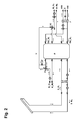
- Fig. 2 there is a connecting line with a spill valve Ü 'on the heat supply side of the buffer memory P.
- a parallel connection of domestic hot water heating and heating is achieved.
- the valve V1 also clears the path AB-B to heat the upper part of the buffer memory P with heat from the flow line K_VL from the conventional heat generator.
- the heating circuit now draws the required volume flow through the bypass line U and the connecting line with an overflow valve Ü 'before the buffer memory P, namely from a branch after the first valve V1, from the portion of the flow line K_VL from the conventional heat generator to the buffer P.
- the buffer memory P only serves as a pendulum storage, without specifically Schuungswasservolumen is stored.
Landscapes
- Engineering & Computer Science (AREA)
- Physics & Mathematics (AREA)
- Thermal Sciences (AREA)
- Chemical & Material Sciences (AREA)
- Combustion & Propulsion (AREA)
- Mechanical Engineering (AREA)
- General Engineering & Computer Science (AREA)
- Life Sciences & Earth Sciences (AREA)
- Sustainable Development (AREA)
- Sustainable Energy (AREA)
- Water Supply & Treatment (AREA)
- Heat-Pump Type And Storage Water Heaters (AREA)
Applications Claiming Priority (1)
| Application Number | Priority Date | Filing Date | Title |
|---|---|---|---|
| DE102009034657.0A DE102009034657B4 (de) | 2009-07-24 | 2009-07-24 | Wärmeversorgungssystem |
Publications (2)
| Publication Number | Publication Date |
|---|---|
| EP2292982A2 true EP2292982A2 (fr) | 2011-03-09 |
| EP2292982A3 EP2292982A3 (fr) | 2016-08-17 |
Family
ID=43127302
Family Applications (1)
| Application Number | Title | Priority Date | Filing Date |
|---|---|---|---|
| EP10169345.5A Withdrawn EP2292982A3 (fr) | 2009-07-24 | 2010-07-13 | Système d'alimentation en chaleur |
Country Status (2)
| Country | Link |
|---|---|
| EP (1) | EP2292982A3 (fr) |
| DE (1) | DE102009034657B4 (fr) |
Families Citing this family (1)
| Publication number | Priority date | Publication date | Assignee | Title |
|---|---|---|---|---|
| CN103157701A (zh) * | 2011-12-14 | 2013-06-19 | 银川海力特液压机械有限公司 | 带有液压弹簧回路的矫直机 |
Family Cites Families (3)
| Publication number | Priority date | Publication date | Assignee | Title |
|---|---|---|---|---|
| DE19511369A1 (de) * | 1994-03-28 | 1995-10-05 | Vaillant Joh Gmbh & Co | Wasserheizanlage zur Bereitung von Brauch- und Heizwasser |
| DE202007009391U1 (de) | 2007-06-29 | 2007-09-13 | Parabel Gmbh | Energiezentrale |
| DE102007031134B3 (de) * | 2007-06-29 | 2008-05-15 | Parabel Gmbh | Verfahren zur Steuerung eines Wärmeerzeugers in einer Energiezentrale |
-
2009
- 2009-07-24 DE DE102009034657.0A patent/DE102009034657B4/de not_active Expired - Fee Related
-
2010
- 2010-07-13 EP EP10169345.5A patent/EP2292982A3/fr not_active Withdrawn
Non-Patent Citations (1)
| Title |
|---|
| None |
Also Published As
| Publication number | Publication date |
|---|---|
| DE102009034657B4 (de) | 2019-02-07 |
| DE102009034657A1 (de) | 2011-03-31 |
| EP2292982A3 (fr) | 2016-08-17 |
Similar Documents
| Publication | Publication Date | Title |
|---|---|---|
| EP0001419B1 (fr) | Installation de chauffage central et de préparation d'eau chaude pour usage domestique comportant une pompe à chaleur | |
| DE2459171A1 (de) | Verfahren und vorrichtung zur erwaermung von fliessmitteln | |
| DE2831017C2 (fr) | ||
| AT508481B1 (de) | Verfahren zur erwärmung von brauchwasser | |
| EP0819893B1 (fr) | Installation de chauffage | |
| DE102009034657B4 (de) | Wärmeversorgungssystem | |
| CH626983A5 (en) | Heat exchanger | |
| DE102021211129A1 (de) | Hybridheizsystem zum Bereitstellen von Brauchwasser und Heizungswärme | |
| DE202007010410U1 (de) | Vorrichtung zur Aufrechterhaltung der Pufferspeicher-Schichtung | |
| DE102008061135A1 (de) | Verfahren zum Steuern oder Regeln einer Heizungsanlage und Heizanlage | |
| DE20019028U1 (de) | Zentralheizungssystem mit Wärmespeicherung | |
| EP1878974A1 (fr) | Accumulateur combiné | |
| EP1898160B1 (fr) | Procédé de regulation d'une installation de chauffage et installation de chauffage permettant le mettre en oeuvre | |
| DE102011118721A1 (de) | Heizungsvorrichtung mit einem Fluidspeicher und ein Verfahren zur Beladung eines Fluidspeichers | |
| DE102007062342B4 (de) | Verfahren und Anordnung zur Erhöhung des Temperaturniveaus im Kreislauf solarthermischer Anlagen oder Blockheizkraftwerke | |
| DE3809251C2 (fr) | ||
| AT409659B (de) | Schichtenspeicher-anlage | |
| DE3238285A1 (de) | System zum zufuehren von waermeenergie aus einem aeusseren waermekreislauf an einen brauchwasserkreislauf, insbesondere brauchwasserspeicher | |
| AT524058A4 (de) | Anlage zur Beaufschlagung wenigstens eines Heizkreises mit Erdwärme | |
| DE102013001533B4 (de) | Solarvorlaufumschlatung zur Stagnationswärmedissipation | |
| AT501612B1 (de) | Verfahren zum betreiben einer warmwasserbereitungsanlage und warmwasserbereitungsanlage | |
| DE19910829B4 (de) | Mehrkreiswärmetauscher | |
| DE102005040456A1 (de) | Kältemittelkreislauf für eine Wärmepumpe | |
| AT400360B (de) | Wasserheizer | |
| DE19617116A1 (de) | Warmwasserbereiter |
Legal Events
| Date | Code | Title | Description |
|---|---|---|---|
| PUAI | Public reference made under article 153(3) epc to a published international application that has entered the european phase |
Free format text: ORIGINAL CODE: 0009012 |
|
| AK | Designated contracting states |
Kind code of ref document: A2 Designated state(s): AL AT BE BG CH CY CZ DE DK EE ES FI FR GB GR HR HU IE IS IT LI LT LU LV MC MK MT NL NO PL PT RO SE SI SK SM TR |
|
| AX | Request for extension of the european patent |
Extension state: BA ME RS |
|
| PUAL | Search report despatched |
Free format text: ORIGINAL CODE: 0009013 |
|
| AK | Designated contracting states |
Kind code of ref document: A3 Designated state(s): AL AT BE BG CH CY CZ DE DK EE ES FI FR GB GR HR HU IE IS IT LI LT LU LV MC MK MT NL NO PL PT RO SE SI SK SM TR |
|
| AX | Request for extension of the european patent |
Extension state: BA ME RS |
|
| RIC1 | Information provided on ipc code assigned before grant |
Ipc: F24D 3/08 20060101AFI20160708BHEP Ipc: F24D 11/00 20060101ALI20160708BHEP |
|
| STAA | Information on the status of an ep patent application or granted ep patent |
Free format text: STATUS: THE APPLICATION IS DEEMED TO BE WITHDRAWN |
|
| 18D | Application deemed to be withdrawn |
Effective date: 20170218 |