EP2292999A2 - Pressure gas cooler, in particular for compressors - Google Patents
Pressure gas cooler, in particular for compressors Download PDFInfo
- Publication number
- EP2292999A2 EP2292999A2 EP10166515A EP10166515A EP2292999A2 EP 2292999 A2 EP2292999 A2 EP 2292999A2 EP 10166515 A EP10166515 A EP 10166515A EP 10166515 A EP10166515 A EP 10166515A EP 2292999 A2 EP2292999 A2 EP 2292999A2
- Authority
- EP
- European Patent Office
- Prior art keywords
- housing
- tube bundle
- gas
- cooling tubes
- gas cooler
- Prior art date
- Legal status (The legal status is an assumption and is not a legal conclusion. Google has not performed a legal analysis and makes no representation as to the accuracy of the status listed.)
- Granted
Links
- 238000001816 cooling Methods 0.000 claims abstract description 19
- 239000000110 cooling liquid Substances 0.000 claims description 10
- 239000007788 liquid Substances 0.000 claims description 5
- 238000010276 construction Methods 0.000 claims description 4
- 239000002826 coolant Substances 0.000 claims description 4
- 238000003780 insertion Methods 0.000 claims description 3
- 230000037431 insertion Effects 0.000 claims description 3
- 239000012809 cooling fluid Substances 0.000 claims 1
- 239000007789 gas Substances 0.000 description 32
- 238000004140 cleaning Methods 0.000 description 1
- 239000000112 cooling gas Substances 0.000 description 1
Images


Classifications
-
- F—MECHANICAL ENGINEERING; LIGHTING; HEATING; WEAPONS; BLASTING
- F28—HEAT EXCHANGE IN GENERAL
- F28D—HEAT-EXCHANGE APPARATUS, NOT PROVIDED FOR IN ANOTHER SUBCLASS, IN WHICH THE HEAT-EXCHANGE MEDIA DO NOT COME INTO DIRECT CONTACT
- F28D7/00—Heat-exchange apparatus having stationary tubular conduit assemblies for both heat-exchange media, the media being in contact with different sides of a conduit wall
- F28D7/16—Heat-exchange apparatus having stationary tubular conduit assemblies for both heat-exchange media, the media being in contact with different sides of a conduit wall the conduits being arranged in parallel spaced relation
- F28D7/1615—Heat-exchange apparatus having stationary tubular conduit assemblies for both heat-exchange media, the media being in contact with different sides of a conduit wall the conduits being arranged in parallel spaced relation the conduits being inside a casing and extending at an angle to the longitudinal axis of the casing; the conduits crossing the conduit for the other heat exchange medium
- F28D7/1623—Heat-exchange apparatus having stationary tubular conduit assemblies for both heat-exchange media, the media being in contact with different sides of a conduit wall the conduits being arranged in parallel spaced relation the conduits being inside a casing and extending at an angle to the longitudinal axis of the casing; the conduits crossing the conduit for the other heat exchange medium with particular pattern of flow of the heat exchange media, e.g. change of flow direction
-
- F—MECHANICAL ENGINEERING; LIGHTING; HEATING; WEAPONS; BLASTING
- F28—HEAT EXCHANGE IN GENERAL
- F28D—HEAT-EXCHANGE APPARATUS, NOT PROVIDED FOR IN ANOTHER SUBCLASS, IN WHICH THE HEAT-EXCHANGE MEDIA DO NOT COME INTO DIRECT CONTACT
- F28D7/00—Heat-exchange apparatus having stationary tubular conduit assemblies for both heat-exchange media, the media being in contact with different sides of a conduit wall
- F28D7/06—Heat-exchange apparatus having stationary tubular conduit assemblies for both heat-exchange media, the media being in contact with different sides of a conduit wall the conduits having a single U-bend
-
- F—MECHANICAL ENGINEERING; LIGHTING; HEATING; WEAPONS; BLASTING
- F28—HEAT EXCHANGE IN GENERAL
- F28D—HEAT-EXCHANGE APPARATUS, NOT PROVIDED FOR IN ANOTHER SUBCLASS, IN WHICH THE HEAT-EXCHANGE MEDIA DO NOT COME INTO DIRECT CONTACT
- F28D21/00—Heat-exchange apparatus not covered by any of the groups F28D1/00 - F28D20/00
- F28D2021/0019—Other heat exchangers for particular applications; Heat exchange systems not otherwise provided for
- F28D2021/0038—Other heat exchangers for particular applications; Heat exchange systems not otherwise provided for for drying or dehumidifying gases or vapours
Definitions
- the head piece preferably has an end plate which can be fastened to the casing of the housing and has an inlet for cooling liquid and a cooling liquid outlet, and a chamber which is subdivided into chambers.
- the front plate and the liquid space thereby expediently form a unit designed as a welded construction, to which the tube sheet is detachably fastened.
- the tube bundle with the connected thereto head piece form a replaceable use of the compressed gas cooler, which can be removed, for example, for cleaning purposes.
- the housing and the exchangeable tube bundle can be individually adapted to different sized compressors of a compressor series. In this case, the angle of attack of the tube bundle relevant angle of attack can be corrected and optimized while maintaining both the structural design of the housing shell and the tube bundle.
Landscapes
- Engineering & Computer Science (AREA)
- Physics & Mathematics (AREA)
- Thermal Sciences (AREA)
- Mechanical Engineering (AREA)
- General Engineering & Computer Science (AREA)
- Heat-Exchange Devices With Radiators And Conduit Assemblies (AREA)
- Structures Of Non-Positive Displacement Pumps (AREA)
- Compressor (AREA)
Abstract
Description
Die Erfindung betrifft einen Druckgaskühler, insbesondere für Kompressoren, mit einem Rohrbündel aus parallelen Kühlrohren für die Durchleitung einer Kühlflüssigkeit und mit einem zylindrischen Gehäuse, das an seinem einen Ende geschlossen ist und an seinem anderen Ende eine stirnseitige Öffnung zum Einsetzen des Rohrbündels aufweist, wobei die Kühlrohre einseitig an einen Rohrboden eines in der stirnseitigen Öffnung des Gehäuses befestigbaren Kopfstückes angeschlossen sind und wobei am Umfang des Gehäuses Stutzen für einen Gaseinlass und einen Gasauslass angeordnet sind, die in Gehäuselängsrichtung voneinander beabstandet sind.The invention relates to a compressed gas cooler, in particular for compressors, with a tube bundle of parallel cooling tubes for the passage of a cooling liquid and with a cylindrical housing which is closed at one end and at its other end has an end opening for insertion of the tube bundle, wherein the Cooling tubes are connected on one side to a tube bottom of an attachable in the frontal opening of the housing head piece and wherein at the periphery of the housing stubs for a gas inlet and a gas outlet are arranged, which are spaced apart in the housing longitudinal direction.
Der Druckgaskühler kann beispielsweise in mehrstufigen Verdichteranlagen als Zwischenkühler eingesetzt werden, um das verdichtete Gas zwischen zwei Kompressorstufen auf einen neuen Ansaugzustand abzukühlen. Der Druckgaskühler ist seiner Bauart nach ein Rohrbündelwärmetauscher. Das Kopfstück weist Anschlüsse für Zuführung von Kühlflüssigkeit und den Auslass von Kühlflüssigkeit auf. An dem zum Kopfstück abgewandten Ende der Kühlrohre ist eine Einrichtung vorgesehen, um die Kühlflüssigkeit umzulenken. Die Strömungsrichtung des Gases ist überwiegend quer zu den Kühlrohren des Rohrbündels ausgerichtet, wobei sich bzgl. der Wärmeübertragung zwischen Kühlflüssigkeit und Gas auch eine Mischform aus Kreuzstrom, Gegenstrom und Gleichstrom einstellen kann. Die Stutzen für den Gaseinlass und den Gasauslass können individuell am Gehäusemantel angeordnet werden, und zwar unter Berücksichtigung der an einen Kompressor angeschlossenen Verrohrung.The compressed gas cooler can be used for example in multi-stage compressor systems as an intercooler to cool the compressed gas between two compressor stages to a new intake state. The compressed gas cooler is a tubular heat exchanger in its design. The header has ports for supplying coolant and the outlet of coolant. At the end remote from the head piece of the cooling tubes, a device is provided to divert the cooling liquid. The flow direction of the gas is predominantly oriented transversely to the cooling tubes of the tube bundle, wherein with respect to the heat transfer between the cooling liquid and gas, a mixed form of cross-flow, countercurrent and direct current can be set. The nozzles for the gas inlet and the gas outlet can be individually arranged on the housing shell, taking into account the piping connected to a compressor.
Druckgaskühler des beschriebenen Aufbaus haben sich an sich bewährt. Die Erfindung befasst sich mit der Aufgabe, die Strömungsverteilung und Strömungsführung des Gases innerhalb des Apparates zu optimieren. Das Wärmeübertragungsverhalten soll weiter verbessert und der gasseitige Strömungsdruckverlust reduziert werden.Pressure gas coolers of the structure described have proven themselves. The invention is concerned with the task of flow distribution and flow guidance to optimize the gas within the apparatus. The heat transfer behavior should be further improved and the gas-side flow pressure loss should be reduced.
Ausgehend von einem Druckgaskühler mit den eingangs beschriebenen Merkmalen wird die Aufgabe erfindungsgemäß dadurch gelöst, dass die Kühlrohre des Rohrbündels unter einem Anstellwinkel von 2° bis 10° schräg zur Längsachse des zylindrischen Gehäuses ausgerichtet sind und dass zumindest der Gaseinlass-Stutzen an einem Gehäuseabschnitt angeordnet ist, der infolge der Schrägstellung der Kühlrohre von dem Rohrbündel weiter beabstandet ist als der in Umfangsrichtung gegenüberliegende Gehäuseabschnitt. Dabei ist vorzugsweise zumindest die Mittelachse des Gaseinlass-Stutzens mit einem radialen Versatz quer zur Längsachse des Gehäuses ausgerichtet.Starting from a pressure gas cooler with the features described above, the object is achieved in that the cooling tubes of the tube bundle are aligned at an angle of 2 ° to 10 ° obliquely to the longitudinal axis of the cylindrical housing and that at least the gas inlet nozzle is arranged on a housing portion which is further spaced from the tube bundle due to the inclination of the cooling tubes than the circumferentially opposed housing section. In this case, preferably at least the center axis of the gas inlet nozzle is aligned with a radial offset transversely to the longitudinal axis of the housing.
Die erfindungsgemäßen Maßnahmen bewirken eine verbesserte und druckverlustärmere Anströmung des Rohrbündels. Ferner lassen sich höhere Gasgeschwindigkeiten durch das Rohrbündel realisieren, so dass eine kompaktere Bauweise des Druckgaskühlers möglich ist. Insgesamt verbessert sich auch das Wärmeübertragungsverhalten des Apparates.The measures according to the invention bring about an improved and lower pressure flow of the tube bundle. Furthermore, higher gas velocities can be realized by the tube bundle, so that a more compact design of the compressed gas cooler is possible. Overall, the heat transfer behavior of the apparatus also improves.
Gemäß einer bevorzugten Ausführung der Erfindung sind beide Stutzen für den Gaseinlass und den Gasauslass an Gehäuseabschnitten des Gehäusemantels angeordnet, die infolge der Schrägstellung der Kühlrohre von dem Rohrbündel weiter beabstandet sind als die in Umfangsrichtung jeweils gegenüberliegenden Gehäuseabschnitte, wobei die Mittelachse beider Stutzen jeweils mit einem radialen Versatz quer zur Längsachse des Gehäuses ausgerichtet ist. Die Schrägstellung des Rohrbündels schafft einen größeren Freiraum sowohl im Einströmbereich des Gases als auch im Ausströmbereich. Dadurch, dass die Mittelachse der Stutzen jeweils mit einem radialen Versatz quer zur Längsachse des Gehäuses ausgerichtet ist, wird eine Rotationsströmung des das Gehäuse durchströmenden Gases angeregt.According to a preferred embodiment of the invention, both nozzles for the gas inlet and the gas outlet are arranged on housing portions of the housing shell, which are further spaced from the tube bundle as a result of the inclination of the cooling tubes than the circumferentially opposite housing sections, wherein the central axis of both nozzles each with a radial Offset is aligned transversely to the longitudinal axis of the housing. The oblique position of the tube bundle creates a greater freedom both in the inflow region of the gas and in the outflow region. Characterized in that the central axis of the nozzle each with a radial offset transversely to the longitudinal axis is aligned with the housing, a rotational flow of the housing flowing through the gas is excited.
Das Kopfstück weist vorzugsweise eine an den Mantel des Gehäuses befestigbare Stirnplatte mit einem Einlass für Kühlflüssigkeit und einen Kühlflüssigkeitsauslass sowie einen in Kammern unterteilten Flüssigkeitsraum auf. Die Stirnplatte und der Flüssigkeitsraum bilden dabei zweckmäßig eine als Schweißkonstruktion ausgebildete Einheit, an der der Rohrboden lösbar befestigt ist. Das Rohrbündel mit dem daran angeschlossenen Kopfstück bilden einen austauschbaren Einsatz des Druckgaskühlers, der beispielsweise zu Reinigungszwecken ausgebaut werden kann. Das Gehäuse und das austauschbare Rohrbündel können individuell an unterschiedlich große Kompressoren einer Verdichterbaureihe angepasst werden. Dabei kann auch der die Schrägstellung des Rohrbündels betreffende Anstellwinkel unter Beibehaltung sowohl des konstruktiven Aufbaus des Gehäusemantels als auch des Rohrbündels korrigiert und optimiert werden.The head piece preferably has an end plate which can be fastened to the casing of the housing and has an inlet for cooling liquid and a cooling liquid outlet, and a chamber which is subdivided into chambers. The front plate and the liquid space thereby expediently form a unit designed as a welded construction, to which the tube sheet is detachably fastened. The tube bundle with the connected thereto head piece form a replaceable use of the compressed gas cooler, which can be removed, for example, for cleaning purposes. The housing and the exchangeable tube bundle can be individually adapted to different sized compressors of a compressor series. In this case, the angle of attack of the tube bundle relevant angle of attack can be corrected and optimized while maintaining both the structural design of the housing shell and the tube bundle.
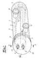
Im Folgenden wird die Erfindung anhand einer lediglich ein Ausführungsbeispiel darstellenden Zeichnung erläutert. Es zeigen schematisch
- Fig. 1
- einen Druckgaskühler für einen Kompressor, insbesondere einen Turbo- verdichter,
- Fig. 2
- den Schnitt A-A aus
Fig. 1 und - Fig. 3
- den Schnitt B-B aus
Fig. 1 .
- Fig. 1
- a compressed gas cooler for a compressor, in particular a turbo-compressor,
- Fig. 2
- the cut AA
Fig. 1 and - Fig. 3
- the cut BB off
Fig. 1 ,
Der in den Figuren dargestellte Druckgaskühler ist seiner Bauart nach ein Rohrbündelwärmetauscher. Er besteht in seinem grundsätzlichen Aufbau aus einem Rohrbündel 1 aus parallelen Kühlrohren 2 für die Durchleitung einer Kühlflüssigkeit und einem zylindrischen Gehäuse 3, das an seinem einen Ende geschlossen ist und an seinem anderen Ende eine stirnseitige Öffnung 4 zum Einsetzen des Rohrbündels 1 aufweist. Die Kühlrohre 2 sind einseitig an einen Rohrboden 5 eines in der stirnseitigen Öffnung 4 des Gehäuses 3 befestigbaren Kopfstückes 6 angeschlossen, welches einen Einlass 7 für die Kühlflüssigkeit sowie einen Auslass 8 für die Kühlflüssigkeit aufweist. An dem von dem Kopfstück 6 abgewandten Ende der Kühlrohre ist eine in an sich bekannter Weise ausgebildete Strömungsumlenkung 9 vorgesehen, so dass jeweils eine gleiche Anzahl von Kühlrohren 2 in der einen Strömungsrichtung und der anderen Strömungsrichtung durchströmt werden. Am Umfang des Gehäuses 3 sind Stutzen 10, 11 für ein Gaseinlass und ein Gasauslass angeordnet, die in Gehäuselängsrichtung voneinander beabstandet sind.The pressure gas cooler shown in the figures is a tube bundle heat exchanger according to its design. It consists in its basic structure of a tube bundle 1 of
Insbesondere der Schnittdarstellung in
Das Kopfstück 6 weist eine an dem Mantel des Gehäuses 3 befestigbare Stirnplatte 13 mit einem Einlass 7 für Kühlflüssigkeit und einen Kühlflüssigkeitsauslass 8 sowie einen in Kammern 15, 16 unterteilten Flüssigkeitsraum auf. Die Stirnplatte 13 und der Flüssigkeitsraum 14 bilden zweckmäßig eine als Schweißkonstruktion ausgebildete Einheit 17, an der der Rohrboden 5 lösbar befestigt ist.The head piece 6 has an attachable to the shell of the
Durch die erfindungsgemäße Schrägstellung des Rohrbündels 1 innerhalb des Gehäuses 3, insbesondere in Verbindung mit der beschriebenen Anordnung der Stutzen 10, 11 für den Gaseinlass und Gasauslass, kann die Strömungsverteilung und Strömungsführung des Gases durch das Rohrbündel 1 verbessert werden. Im Vergleich zu einem Druckgaskühler gleichen Aufbaus und gleicher Größe, dessen Rohrbündel 1 in der Längsachse des Gehäuses und parallel zu dieser angeordnet ist, lassen sich höhere Gasgeschwindigkeiten bei gleichem Strömungsdruckverlust realisieren. Insgesamt kann das Wärmeübertragungsverhalten verbessert werden.The inventive oblique position of the tube bundle 1 within the
Claims (5)
einem Rohrbündel (1) aus parallelen Kühlrohren (2) für die Durchleitung einer Kühlflüssigkeit und
einem zylindrischen Gehäuse (3), das an seinem einen Ende geschlossen ist und an seinem anderen Ende eine stirnseitige Öffnung (4) zum Einsetzen des Rohrbündels (1) aufweist,
wobei die Kühlrohre (2) einseitig an einen Rohrboden (5) eines in der stirnseitigen Öffnung (4) des Gehäuses (3) befestigbaren Kopfstückes (6) angeschlossen sind und wobei am Umfang des Gehäuses (3) Stutzen (10, 11) für einen Gaseinlass und einen Gasauslass angeordnet sind, die in Gehäuselängsrichtung voneinander beabstandet sind, dadurch gekennzeichnet, dass die Kühlrohre (2) des Rohrbündels (1) unter einem Anstellwinkel α von 2° bis 10° schräg zur Längsachse (12) des zylindrischen Gehäuses ausgerichtet sind und dass zumindest der Gaseinlass-Stutzen (10) an einem Gehäuseabschnitt angeordnet ist, der infolge der Schrägstellung der Kühlrohre (2) von dem Rohrbündel (1) weiter beabstandet ist als der in Umfangsrichtung gegenüberliegende Gehäuseabschnitt.Compressed-gas cooler, in particular for compressors, with
a tube bundle (1) of parallel cooling tubes (2) for the passage of a cooling liquid and
a cylindrical housing (3) which is closed at its one end and at its other end has an end opening (4) for insertion of the tube bundle (1),
wherein the cooling tubes (2) on one side to a tube plate (5) in the frontal opening (4) of the housing (3) attachable head piece (6) are connected and wherein at the periphery of the housing (3) nozzle (10, 11) for a Gas inlet and a gas outlet are arranged, which are spaced apart in the housing longitudinal direction, characterized in that the cooling tubes (2) of the tube bundle (1) are aligned at an angle α of 2 ° to 10 ° obliquely to the longitudinal axis (12) of the cylindrical housing and in that at least the gas inlet connection piece (10) is arranged on a housing section which, as a result of the oblique position of the cooling tubes (2), is spaced further from the tube bundle (1) than the circumferentially opposite housing section.
Applications Claiming Priority (1)
| Application Number | Priority Date | Filing Date | Title |
|---|---|---|---|
| DE102009039751A DE102009039751B4 (en) | 2009-09-02 | 2009-09-02 | Compressed gas cooler, in particular for compressors |
Publications (3)
| Publication Number | Publication Date |
|---|---|
| EP2292999A2 true EP2292999A2 (en) | 2011-03-09 |
| EP2292999A3 EP2292999A3 (en) | 2012-07-18 |
| EP2292999B1 EP2292999B1 (en) | 2013-05-01 |
Family
ID=43242802
Family Applications (1)
| Application Number | Title | Priority Date | Filing Date |
|---|---|---|---|
| EP10166515.6A Not-in-force EP2292999B1 (en) | 2009-09-02 | 2010-06-18 | Pressure gas cooler, in particular for compressors |
Country Status (6)
| Country | Link |
|---|---|
| US (1) | US8424593B2 (en) |
| EP (1) | EP2292999B1 (en) |
| JP (1) | JP5261445B2 (en) |
| KR (1) | KR101283733B1 (en) |
| CN (1) | CN102003896B (en) |
| DE (1) | DE102009039751B4 (en) |
Families Citing this family (3)
| Publication number | Priority date | Publication date | Assignee | Title |
|---|---|---|---|---|
| DE102009039751B4 (en) | 2009-09-02 | 2011-05-12 | Atlas Copco Energas Gmbh | Compressed gas cooler, in particular for compressors |
| US10537089B2 (en) * | 2013-02-06 | 2020-01-21 | The Curators Of The University Of Missouri | Waste heat recovery systems and methods for a livestock barn |
| FR3132567B1 (en) * | 2022-02-10 | 2024-04-19 | Air Liquide | Improved compactness heat exchanger |
Family Cites Families (30)
| Publication number | Priority date | Publication date | Assignee | Title |
|---|---|---|---|---|
| US1617119A (en) * | 1921-09-16 | 1927-02-08 | Griscom Russell Co | Bent-tube evaporator |
| US1655086A (en) * | 1926-03-26 | 1928-01-03 | Robert L Blanding | Heat exchanger |
| US1841361A (en) * | 1928-11-14 | 1932-01-19 | Niagara Blower Co | Air heater and method of making the same |
| US2036957A (en) * | 1936-02-19 | 1936-04-07 | Griscom Russell Co | Heat exchanger |
| US2519084A (en) * | 1945-03-13 | 1950-08-15 | Westinghouse Electric Corp | Shell and tube heat exchanger having zig-zag tubes |
| US3042379A (en) * | 1959-06-29 | 1962-07-03 | Bell & Gossett Co | Condensers |
| DE1601205A1 (en) * | 1967-10-13 | 1970-08-06 | Ind Companie Kleinewefers Gmbh | Heat exchanger with tubes arranged in a cross-grid shape |
| JPS53109167U (en) * | 1977-02-09 | 1978-09-01 | ||
| US4280556A (en) * | 1980-01-22 | 1981-07-28 | Suntime, Inc. | Heat exchanger-tank assembly for hot water heating system |
| JPS58184487A (en) * | 1982-04-21 | 1983-10-27 | Toshiba Corp | Condenser |
| EP0197823A1 (en) * | 1985-03-20 | 1986-10-15 | Valeo | Heat exchanger for a motor vehicle, particularly of the type for exhaust gases |
| DE3541418A1 (en) * | 1985-11-23 | 1987-05-27 | Steinmueller Gmbh L & C | TUBE BUNDLE AND HEAT EXCHANGING DEVICE WITH THIS TUBE BUNDLE |
| JPH0667408B2 (en) * | 1987-07-13 | 1994-08-31 | テルモ株式会社 | Multi-tube heat exchanger |
| DE3725797C1 (en) * | 1987-08-04 | 1988-08-25 | Komotzki, Michael, 5840 Schwerte, De | |
| US5213156A (en) * | 1989-12-27 | 1993-05-25 | Elge Ab | Heat exchanger and a method for its fabrication |
| JPH0534084A (en) * | 1991-07-27 | 1993-02-09 | Onoda Cement Co Ltd | Heat exchanger |
| JP3948638B2 (en) * | 1997-05-14 | 2007-07-25 | 臼井国際産業株式会社 | EGR gas cooling device |
| DE19832222A1 (en) * | 1998-07-17 | 2000-01-20 | Atlas Copco Energas | Gas cooler for installation in a gearbox turbo compressor system |
| JP2000220972A (en) * | 1998-11-27 | 2000-08-08 | Usui Internatl Ind Co Ltd | Egr gas cooler |
| JP4256515B2 (en) * | 1999-02-04 | 2009-04-22 | 神威産業株式会社 | Multi-tube heat exchanger |
| DE19953612A1 (en) * | 1999-11-08 | 2001-05-10 | Abb Alstom Power Ch Ag | Horizontal heat exchanger with reversal chamber uses line venting chamber descending from topmost possible geodetic point through second medium chamber to chamber on input and output side. |
| DE10100241A1 (en) * | 2001-01-05 | 2002-07-18 | Hde Metallwerk Gmbh | Heat exchanger tube for liquid or gaseous media |
| JP3990161B2 (en) * | 2002-02-08 | 2007-10-10 | 株式会社前川製作所 | EVACON structure of ammonia cooling unit |
| CN2597919Y (en) * | 2003-01-10 | 2004-01-07 | 厦门市立精实业有限公司 | Equipment for cooling air |
| CN1283972C (en) * | 2003-10-17 | 2006-11-08 | 西安交通大学 | Shell-and-tube heat exchanger |
| SE527575C2 (en) * | 2004-02-10 | 2006-04-11 | Scania Cv Abp | Methods and apparatus for air cooling at compressors |
| JP2006105464A (en) * | 2004-10-04 | 2006-04-20 | Toyota Motor Corp | Heat exchanger and heat exchange device |
| CN2869738Y (en) * | 2005-12-21 | 2007-02-14 | 李建明 | Aluminium inner-finned-tube heat exchanger |
| CN201184762Y (en) * | 2008-01-08 | 2009-01-21 | 王全龄 | High-efficiency liquid-filled type coupling heat exchanger |
| DE102009039751B4 (en) | 2009-09-02 | 2011-05-12 | Atlas Copco Energas Gmbh | Compressed gas cooler, in particular for compressors |
-
2009
- 2009-09-02 DE DE102009039751A patent/DE102009039751B4/en not_active Expired - Fee Related
-
2010
- 2010-06-18 EP EP10166515.6A patent/EP2292999B1/en not_active Not-in-force
- 2010-07-01 US US12/828,458 patent/US8424593B2/en not_active Expired - Fee Related
- 2010-07-27 JP JP2010167674A patent/JP5261445B2/en not_active Expired - Fee Related
- 2010-08-09 CN CN201010250972.8A patent/CN102003896B/en not_active Expired - Fee Related
- 2010-09-01 KR KR1020100085614A patent/KR101283733B1/en not_active Expired - Fee Related
Non-Patent Citations (1)
| Title |
|---|
| None |
Also Published As
| Publication number | Publication date |
|---|---|
| DE102009039751A1 (en) | 2011-03-17 |
| CN102003896B (en) | 2014-06-04 |
| JP5261445B2 (en) | 2013-08-14 |
| DE102009039751B4 (en) | 2011-05-12 |
| EP2292999B1 (en) | 2013-05-01 |
| JP2011052953A (en) | 2011-03-17 |
| KR20110025140A (en) | 2011-03-09 |
| US8424593B2 (en) | 2013-04-23 |
| CN102003896A (en) | 2011-04-06 |
| US20110048686A1 (en) | 2011-03-03 |
| KR101283733B1 (en) | 2013-07-08 |
| EP2292999A3 (en) | 2012-07-18 |
Similar Documents
| Publication | Publication Date | Title |
|---|---|---|
| WO2003054465A1 (en) | Device for exchanging heat | |
| DE102017203058A1 (en) | Heat exchanger and reactor | |
| DE112016004891T5 (en) | exhaust gas cooler | |
| EP2292999B1 (en) | Pressure gas cooler, in particular for compressors | |
| DE3513936C2 (en) | Cooling device for a multi-stage compressor | |
| DE10348141B3 (en) | Inner heat exchanger for high pressure cooling medium providing dual function as accumulator and cooling medium collector | |
| DE602005003216T2 (en) | DEVICE FOR PROCESSING HIGHLY CORROSIVE MEANS | |
| CH673886A5 (en) | ||
| DE102015204984A1 (en) | Heat exchanger, in particular for a waste heat utilization device | |
| DE102022213576A1 (en) | HEAT PUMP WITH MULTI-STAGE COMPRESSOR AND SPIRAL CASINGS | |
| DE671913C (en) | Single or multi-housing, multi-stage axial compressor with at least one external intermediate cooler | |
| WO2016131787A1 (en) | Shell and tube heat exchanger having sequentially arranged shell and tube components | |
| DE2350015A1 (en) | OIL SEPARATOR, ESPECIALLY FOR REFRIGERANT COMPRESSORS | |
| EP1741998B1 (en) | Condenser | |
| EP0972945B1 (en) | Gear driven compressor | |
| CH496891A (en) | Compressor system | |
| DE10025325B4 (en) | Accumulator for an air conditioning system | |
| DE10339663A1 (en) | Heat exchanger unit for motor vehicles | |
| DE3023089C2 (en) | Duo refrigerant evaporator | |
| DE112016002286T5 (en) | Heat exchanger with liquid container | |
| EP1724544A1 (en) | Method of heat exchanging and heat exchanger | |
| AT334586B (en) | SUCTION MIXING HEAD FOR VENTILATION OR AIR CONDITIONING SYSTEMS | |
| EP1716377A1 (en) | Device for heat exchange and method for producing one such device | |
| DE2154267A1 (en) | MULTI-STAGE RADIAL TURBO COMPRESSOR | |
| DD284517A5 (en) | TUBE BELT WASHER WITH SWIMMING HEAD |
Legal Events
| Date | Code | Title | Description |
|---|---|---|---|
| PUAI | Public reference made under article 153(3) epc to a published international application that has entered the european phase |
Free format text: ORIGINAL CODE: 0009012 |
|
| AK | Designated contracting states |
Kind code of ref document: A2 Designated state(s): AL AT BE BG CH CY CZ DE DK EE ES FI FR GB GR HR HU IE IS IT LI LT LU LV MC MK MT NL NO PL PT RO SE SI SK SM TR |
|
| AX | Request for extension of the european patent |
Extension state: BA ME RS |
|
| PUAL | Search report despatched |
Free format text: ORIGINAL CODE: 0009013 |
|
| AK | Designated contracting states |
Kind code of ref document: A3 Designated state(s): AL AT BE BG CH CY CZ DE DK EE ES FI FR GB GR HR HU IE IS IT LI LT LU LV MC MK MT NL NO PL PT RO SE SI SK SM TR |
|
| AX | Request for extension of the european patent |
Extension state: BA ME RS |
|
| RIC1 | Information provided on ipc code assigned before grant |
Ipc: F28D 7/16 20060101AFI20120613BHEP |
|
| REG | Reference to a national code |
Ref country code: DE Ref legal event code: R079 Ref document number: 502010003123 Country of ref document: DE Free format text: PREVIOUS MAIN CLASS: F28D0007160000 Ipc: F28D0007060000 |
|
| 17P | Request for examination filed |
Effective date: 20120802 |
|
| RAP1 | Party data changed (applicant data changed or rights of an application transferred) |
Owner name: ATLAS COPCO ENERGAS GMBH |
|
| RIC1 | Information provided on ipc code assigned before grant |
Ipc: F28D 7/06 20060101AFI20120820BHEP |
|
| GRAP | Despatch of communication of intention to grant a patent |
Free format text: ORIGINAL CODE: EPIDOSNIGR1 |
|
| GRAS | Grant fee paid |
Free format text: ORIGINAL CODE: EPIDOSNIGR3 |
|
| GRAA | (expected) grant |
Free format text: ORIGINAL CODE: 0009210 |
|
| AK | Designated contracting states |
Kind code of ref document: B1 Designated state(s): AL AT BE BG CH CY CZ DE DK EE ES FI FR GB GR HR HU IE IS IT LI LT LU LV MC MK MT NL NO PL PT RO SE SI SK SM TR |
|
| REG | Reference to a national code |
Ref country code: GB Ref legal event code: FG4D Free format text: NOT ENGLISH |
|
| REG | Reference to a national code |
Ref country code: AT Ref legal event code: REF Ref document number: 610194 Country of ref document: AT Kind code of ref document: T Effective date: 20130515 Ref country code: CH Ref legal event code: EP |
|
| REG | Reference to a national code |
Ref country code: IE Ref legal event code: FG4D Free format text: LANGUAGE OF EP DOCUMENT: GERMAN |
|
| REG | Reference to a national code |
Ref country code: DE Ref legal event code: R096 Ref document number: 502010003123 Country of ref document: DE Effective date: 20130627 |
|
| REG | Reference to a national code |
Ref country code: SE Ref legal event code: TRGR |
|
| REG | Reference to a national code |
Ref country code: CH Ref legal event code: NV Representative=s name: KELLER AND PARTNER PATENTANWAELTE AG, CH |
|
| REG | Reference to a national code |
Ref country code: NL Ref legal event code: T3 |
|
| REG | Reference to a national code |
Ref country code: LT Ref legal event code: MG4D |
|
| PG25 | Lapsed in a contracting state [announced via postgrant information from national office to epo] |
Ref country code: LT Free format text: LAPSE BECAUSE OF FAILURE TO SUBMIT A TRANSLATION OF THE DESCRIPTION OR TO PAY THE FEE WITHIN THE PRESCRIBED TIME-LIMIT Effective date: 20130501 Ref country code: SI Free format text: LAPSE BECAUSE OF FAILURE TO SUBMIT A TRANSLATION OF THE DESCRIPTION OR TO PAY THE FEE WITHIN THE PRESCRIBED TIME-LIMIT Effective date: 20130501 Ref country code: GR Free format text: LAPSE BECAUSE OF FAILURE TO SUBMIT A TRANSLATION OF THE DESCRIPTION OR TO PAY THE FEE WITHIN THE PRESCRIBED TIME-LIMIT Effective date: 20130802 Ref country code: PT Free format text: LAPSE BECAUSE OF FAILURE TO SUBMIT A TRANSLATION OF THE DESCRIPTION OR TO PAY THE FEE WITHIN THE PRESCRIBED TIME-LIMIT Effective date: 20130902 Ref country code: NO Free format text: LAPSE BECAUSE OF FAILURE TO SUBMIT A TRANSLATION OF THE DESCRIPTION OR TO PAY THE FEE WITHIN THE PRESCRIBED TIME-LIMIT Effective date: 20130801 Ref country code: IS Free format text: LAPSE BECAUSE OF FAILURE TO SUBMIT A TRANSLATION OF THE DESCRIPTION OR TO PAY THE FEE WITHIN THE PRESCRIBED TIME-LIMIT Effective date: 20130901 Ref country code: ES Free format text: LAPSE BECAUSE OF FAILURE TO SUBMIT A TRANSLATION OF THE DESCRIPTION OR TO PAY THE FEE WITHIN THE PRESCRIBED TIME-LIMIT Effective date: 20130812 |
|
| PG25 | Lapsed in a contracting state [announced via postgrant information from national office to epo] |
Ref country code: HR Free format text: LAPSE BECAUSE OF FAILURE TO SUBMIT A TRANSLATION OF THE DESCRIPTION OR TO PAY THE FEE WITHIN THE PRESCRIBED TIME-LIMIT Effective date: 20130501 Ref country code: CY Free format text: LAPSE BECAUSE OF FAILURE TO SUBMIT A TRANSLATION OF THE DESCRIPTION OR TO PAY THE FEE WITHIN THE PRESCRIBED TIME-LIMIT Effective date: 20130501 Ref country code: BG Free format text: LAPSE BECAUSE OF FAILURE TO SUBMIT A TRANSLATION OF THE DESCRIPTION OR TO PAY THE FEE WITHIN THE PRESCRIBED TIME-LIMIT Effective date: 20130801 Ref country code: PL Free format text: LAPSE BECAUSE OF FAILURE TO SUBMIT A TRANSLATION OF THE DESCRIPTION OR TO PAY THE FEE WITHIN THE PRESCRIBED TIME-LIMIT Effective date: 20130501 |
|
| PG25 | Lapsed in a contracting state [announced via postgrant information from national office to epo] |
Ref country code: LV Free format text: LAPSE BECAUSE OF FAILURE TO SUBMIT A TRANSLATION OF THE DESCRIPTION OR TO PAY THE FEE WITHIN THE PRESCRIBED TIME-LIMIT Effective date: 20130501 |
|
| PG25 | Lapsed in a contracting state [announced via postgrant information from national office to epo] |
Ref country code: EE Free format text: LAPSE BECAUSE OF FAILURE TO SUBMIT A TRANSLATION OF THE DESCRIPTION OR TO PAY THE FEE WITHIN THE PRESCRIBED TIME-LIMIT Effective date: 20130501 Ref country code: MC Free format text: LAPSE BECAUSE OF FAILURE TO SUBMIT A TRANSLATION OF THE DESCRIPTION OR TO PAY THE FEE WITHIN THE PRESCRIBED TIME-LIMIT Effective date: 20130501 Ref country code: DK Free format text: LAPSE BECAUSE OF FAILURE TO SUBMIT A TRANSLATION OF THE DESCRIPTION OR TO PAY THE FEE WITHIN THE PRESCRIBED TIME-LIMIT Effective date: 20130501 Ref country code: CZ Free format text: LAPSE BECAUSE OF FAILURE TO SUBMIT A TRANSLATION OF THE DESCRIPTION OR TO PAY THE FEE WITHIN THE PRESCRIBED TIME-LIMIT Effective date: 20130501 Ref country code: SK Free format text: LAPSE BECAUSE OF FAILURE TO SUBMIT A TRANSLATION OF THE DESCRIPTION OR TO PAY THE FEE WITHIN THE PRESCRIBED TIME-LIMIT Effective date: 20130501 |
|
| PG25 | Lapsed in a contracting state [announced via postgrant information from national office to epo] |
Ref country code: RO Free format text: LAPSE BECAUSE OF FAILURE TO SUBMIT A TRANSLATION OF THE DESCRIPTION OR TO PAY THE FEE WITHIN THE PRESCRIBED TIME-LIMIT Effective date: 20130501 |
|
| PLBE | No opposition filed within time limit |
Free format text: ORIGINAL CODE: 0009261 |
|
| STAA | Information on the status of an ep patent application or granted ep patent |
Free format text: STATUS: NO OPPOSITION FILED WITHIN TIME LIMIT |
|
| REG | Reference to a national code |
Ref country code: IE Ref legal event code: MM4A |
|
| 26N | No opposition filed |
Effective date: 20140204 |
|
| PG25 | Lapsed in a contracting state [announced via postgrant information from national office to epo] |
Ref country code: IE Free format text: LAPSE BECAUSE OF NON-PAYMENT OF DUE FEES Effective date: 20130618 |
|
| REG | Reference to a national code |
Ref country code: DE Ref legal event code: R097 Ref document number: 502010003123 Country of ref document: DE Effective date: 20140204 |
|
| PGFP | Annual fee paid to national office [announced via postgrant information from national office to epo] |
Ref country code: GB Payment date: 20140618 Year of fee payment: 5 |
|
| PGFP | Annual fee paid to national office [announced via postgrant information from national office to epo] |
Ref country code: SE Payment date: 20140618 Year of fee payment: 5 Ref country code: NL Payment date: 20140618 Year of fee payment: 5 Ref country code: CH Payment date: 20140618 Year of fee payment: 5 Ref country code: DE Payment date: 20140625 Year of fee payment: 5 Ref country code: FI Payment date: 20140611 Year of fee payment: 5 Ref country code: IT Payment date: 20140623 Year of fee payment: 5 |
|
| PGFP | Annual fee paid to national office [announced via postgrant information from national office to epo] |
Ref country code: BE Payment date: 20140620 Year of fee payment: 5 |
|
| PGFP | Annual fee paid to national office [announced via postgrant information from national office to epo] |
Ref country code: FR Payment date: 20140619 Year of fee payment: 5 |
|
| PG25 | Lapsed in a contracting state [announced via postgrant information from national office to epo] |
Ref country code: MT Free format text: LAPSE BECAUSE OF FAILURE TO SUBMIT A TRANSLATION OF THE DESCRIPTION OR TO PAY THE FEE WITHIN THE PRESCRIBED TIME-LIMIT Effective date: 20130501 |
|
| REG | Reference to a national code |
Ref country code: CH Ref legal event code: PCAR Free format text: NEW ADDRESS: EIGERSTRASSE 2 POSTFACH, 3000 BERN 14 (CH) |
|
| PG25 | Lapsed in a contracting state [announced via postgrant information from national office to epo] |
Ref country code: SM Free format text: LAPSE BECAUSE OF FAILURE TO SUBMIT A TRANSLATION OF THE DESCRIPTION OR TO PAY THE FEE WITHIN THE PRESCRIBED TIME-LIMIT Effective date: 20130501 |
|
| PG25 | Lapsed in a contracting state [announced via postgrant information from national office to epo] |
Ref country code: TR Free format text: LAPSE BECAUSE OF FAILURE TO SUBMIT A TRANSLATION OF THE DESCRIPTION OR TO PAY THE FEE WITHIN THE PRESCRIBED TIME-LIMIT Effective date: 20130501 |
|
| PG25 | Lapsed in a contracting state [announced via postgrant information from national office to epo] |
Ref country code: LU Free format text: LAPSE BECAUSE OF NON-PAYMENT OF DUE FEES Effective date: 20130618 Ref country code: MK Free format text: LAPSE BECAUSE OF FAILURE TO SUBMIT A TRANSLATION OF THE DESCRIPTION OR TO PAY THE FEE WITHIN THE PRESCRIBED TIME-LIMIT Effective date: 20130501 Ref country code: HU Free format text: LAPSE BECAUSE OF FAILURE TO SUBMIT A TRANSLATION OF THE DESCRIPTION OR TO PAY THE FEE WITHIN THE PRESCRIBED TIME-LIMIT; INVALID AB INITIO Effective date: 20100618 |
|
| REG | Reference to a national code |
Ref country code: DE Ref legal event code: R119 Ref document number: 502010003123 Country of ref document: DE |
|
| PG25 | Lapsed in a contracting state [announced via postgrant information from national office to epo] |
Ref country code: IT Free format text: LAPSE BECAUSE OF NON-PAYMENT OF DUE FEES Effective date: 20150618 Ref country code: FI Free format text: LAPSE BECAUSE OF NON-PAYMENT OF DUE FEES Effective date: 20150618 |
|
| REG | Reference to a national code |
Ref country code: CH Ref legal event code: PL |
|
| REG | Reference to a national code |
Ref country code: SE Ref legal event code: EUG |
|
| GBPC | Gb: european patent ceased through non-payment of renewal fee |
Effective date: 20150618 |
|
| PG25 | Lapsed in a contracting state [announced via postgrant information from national office to epo] |
Ref country code: SE Free format text: LAPSE BECAUSE OF NON-PAYMENT OF DUE FEES Effective date: 20150619 |
|
| REG | Reference to a national code |
Ref country code: NL Ref legal event code: MM Effective date: 20150701 |
|
| REG | Reference to a national code |
Ref country code: FR Ref legal event code: ST Effective date: 20160229 |
|
| PG25 | Lapsed in a contracting state [announced via postgrant information from national office to epo] |
Ref country code: CH Free format text: LAPSE BECAUSE OF NON-PAYMENT OF DUE FEES Effective date: 20150630 Ref country code: LI Free format text: LAPSE BECAUSE OF NON-PAYMENT OF DUE FEES Effective date: 20150630 Ref country code: GB Free format text: LAPSE BECAUSE OF NON-PAYMENT OF DUE FEES Effective date: 20150618 Ref country code: DE Free format text: LAPSE BECAUSE OF NON-PAYMENT OF DUE FEES Effective date: 20160101 Ref country code: NL Free format text: LAPSE BECAUSE OF NON-PAYMENT OF DUE FEES Effective date: 20150701 |
|
| PG25 | Lapsed in a contracting state [announced via postgrant information from national office to epo] |
Ref country code: FR Free format text: LAPSE BECAUSE OF NON-PAYMENT OF DUE FEES Effective date: 20150630 |
|
| REG | Reference to a national code |
Ref country code: AT Ref legal event code: MM01 Ref document number: 610194 Country of ref document: AT Kind code of ref document: T Effective date: 20150618 |
|
| PG25 | Lapsed in a contracting state [announced via postgrant information from national office to epo] |
Ref country code: AT Free format text: LAPSE BECAUSE OF NON-PAYMENT OF DUE FEES Effective date: 20150618 |
|
| PG25 | Lapsed in a contracting state [announced via postgrant information from national office to epo] |
Ref country code: BE Free format text: LAPSE BECAUSE OF NON-PAYMENT OF DUE FEES Effective date: 20150630 |
|
| PG25 | Lapsed in a contracting state [announced via postgrant information from national office to epo] |
Ref country code: AL Free format text: LAPSE BECAUSE OF FAILURE TO SUBMIT A TRANSLATION OF THE DESCRIPTION OR TO PAY THE FEE WITHIN THE PRESCRIBED TIME-LIMIT Effective date: 20130501 |