EP2293013A2 - Dispositif de mesure laser en 3D - Google Patents
Dispositif de mesure laser en 3D Download PDFInfo
- Publication number
- EP2293013A2 EP2293013A2 EP10450139A EP10450139A EP2293013A2 EP 2293013 A2 EP2293013 A2 EP 2293013A2 EP 10450139 A EP10450139 A EP 10450139A EP 10450139 A EP10450139 A EP 10450139A EP 2293013 A2 EP2293013 A2 EP 2293013A2
- Authority
- EP
- European Patent Office
- Prior art keywords
- laser
- measuring device
- laser measuring
- mirror
- pyramid
- Prior art date
- Legal status (The legal status is an assumption and is not a legal conclusion. Google has not performed a legal analysis and makes no representation as to the accuracy of the status listed.)
- Granted
Links
Images


Classifications
-
- G—PHYSICS
- G01—MEASURING; TESTING
- G01C—MEASURING DISTANCES, LEVELS OR BEARINGS; SURVEYING; NAVIGATION; GYROSCOPIC INSTRUMENTS; PHOTOGRAMMETRY OR VIDEOGRAMMETRY
- G01C15/00—Surveying instruments or accessories not provided for in groups G01C1/00 - G01C13/00
- G01C15/002—Active optical surveying means
-
- G—PHYSICS
- G01—MEASURING; TESTING
- G01S—RADIO DIRECTION-FINDING; RADIO NAVIGATION; DETERMINING DISTANCE OR VELOCITY BY USE OF RADIO WAVES; LOCATING OR PRESENCE-DETECTING BY USE OF THE REFLECTION OR RERADIATION OF RADIO WAVES; ANALOGOUS ARRANGEMENTS USING OTHER WAVES
- G01S17/00—Systems using the reflection or reradiation of electromagnetic waves other than radio waves, e.g. lidar systems
- G01S17/02—Systems using the reflection of electromagnetic waves other than radio waves
- G01S17/06—Systems determining position data of a target
- G01S17/08—Systems determining position data of a target for measuring distance only
- G01S17/10—Systems determining position data of a target for measuring distance only using transmission of interrupted, pulse-modulated waves
- G01S17/14—Systems determining position data of a target for measuring distance only using transmission of interrupted, pulse-modulated waves wherein a voltage or current pulse is initiated and terminated in accordance with the pulse transmission and echo reception respectively, e.g. using counters
-
- G—PHYSICS
- G01—MEASURING; TESTING
- G01S—RADIO DIRECTION-FINDING; RADIO NAVIGATION; DETERMINING DISTANCE OR VELOCITY BY USE OF RADIO WAVES; LOCATING OR PRESENCE-DETECTING BY USE OF THE REFLECTION OR RERADIATION OF RADIO WAVES; ANALOGOUS ARRANGEMENTS USING OTHER WAVES
- G01S17/00—Systems using the reflection or reradiation of electromagnetic waves other than radio waves, e.g. lidar systems
- G01S17/02—Systems using the reflection of electromagnetic waves other than radio waves
- G01S17/06—Systems determining position data of a target
- G01S17/42—Simultaneous measurement of distance and other co-ordinates
-
- G—PHYSICS
- G01—MEASURING; TESTING
- G01S—RADIO DIRECTION-FINDING; RADIO NAVIGATION; DETERMINING DISTANCE OR VELOCITY BY USE OF RADIO WAVES; LOCATING OR PRESENCE-DETECTING BY USE OF THE REFLECTION OR RERADIATION OF RADIO WAVES; ANALOGOUS ARRANGEMENTS USING OTHER WAVES
- G01S17/00—Systems using the reflection or reradiation of electromagnetic waves other than radio waves, e.g. lidar systems
- G01S17/88—Lidar systems specially adapted for specific applications
- G01S17/89—Lidar systems specially adapted for specific applications for mapping or imaging
-
- G—PHYSICS
- G01—MEASURING; TESTING
- G01S—RADIO DIRECTION-FINDING; RADIO NAVIGATION; DETERMINING DISTANCE OR VELOCITY BY USE OF RADIO WAVES; LOCATING OR PRESENCE-DETECTING BY USE OF THE REFLECTION OR RERADIATION OF RADIO WAVES; ANALOGOUS ARRANGEMENTS USING OTHER WAVES
- G01S7/00—Details of systems according to groups G01S13/00, G01S15/00, G01S17/00
- G01S7/48—Details of systems according to groups G01S13/00, G01S15/00, G01S17/00 of systems according to group G01S17/00
- G01S7/481—Constructional features, e.g. arrangements of optical elements
- G01S7/4817—Constructional features, e.g. arrangements of optical elements relating to scanning
-
- G—PHYSICS
- G02—OPTICS
- G02B—OPTICAL ELEMENTS, SYSTEMS OR APPARATUS
- G02B26/00—Optical devices or arrangements for the control of light using movable or deformable optical elements
- G02B26/08—Optical devices or arrangements for the control of light using movable or deformable optical elements for controlling the direction of light
- G02B26/10—Scanning systems
- G02B26/12—Scanning systems using multifaceted mirrors
- G02B26/121—Mechanical drive devices for polygonal mirrors
-
- G—PHYSICS
- G02—OPTICS
- G02B—OPTICAL ELEMENTS, SYSTEMS OR APPARATUS
- G02B5/00—Optical elements other than lenses
- G02B5/08—Mirrors
- G02B5/09—Multifaceted or polygonal mirrors, e.g. polygonal scanning mirrors; Fresnel mirrors
Definitions
- the invention relates to a 3D measuring device with a laser rangefinder, which comprises a laser transmitter which emits pulsed or modulated laser radiation. It also comprises a receiving device which receives the radiation reflected by targets.
- the laser transmitter and the receiving device are each preceded by an optical system, in particular a lens.
- the laser rangefinder has an evaluation device, by means of which the distance between the laser rangefinder and the targets is determined from the transit time of the laser pulses or from the phase position of the modulated laser radiation.
- a deflection device for the transmitting and receiving beams, which comprises at least one mirror prism rotating about an axis, or a rotating mirror pyramid, by means of which or which the target space can be scanned with a beam fan and the entire 3D measuring device relative to the target space is translationally and substantially normal to the fan beam movable so that the target space a 3D data set or a corresponding point cloud is generated and for each measurement point, the distance, the deflection angle and the geographical coordinates and the spatial position of the 3D-surveying detected and be stored in a data store.
- Such image acquisition systems are used, for example, in aircraft such as surface aircraft, helicopters or in unmanned drones and serve the measurement of more or less large tracts of land.
- a 3D data set or a digital surface model is generated, which or which can be further processed with known CAD programs.
- the results of this survey are not always easy to interpret, as all elements that extend in the direction of the measuring beams are not clearly reproduced. For example, it is relatively difficult in To identify such a model high-voltage masts, chimneys or wells such as crevasses or avalanches.
- the invention proposes that at least one of the surfaces of the mirror pyramid and an adjacent mirror surface with the axis of rotation include different angles.
- At least two measuring beam scanners line scan the target area from different angles, the lines of measuring points resulting from the different angles of the mirror surfaces being offset in the direction of the translational movement of the 3D surveying device and taking into account the angle of the mirror surfaces and the resulting the position, direction and length of the measuring beam and thus the geographical coordinates of the measuring points are defined in the target space and the totality of the measuring points represent a 3D data set or a point cloud, in which or in which by the different shooting directions shading are largely avoided.
- the light emitted by the laser transmission beam into the reception channel through reflections, etc., of the transmission pulse from the evaluation device is in relation to the temporal position
- the pulse can be processed and used as a start signal for the time measurement between transmission of the laser pulse and reception of the EchoImpulse.
- the echo pulses arriving within a predetermined minimum time interval are not taken into account in the evaluation, wherein the minimum time span is chosen such that scattered laser transmission light in the area of the 3D surveying device certainly remains excluded from the time measurement.
- the mirror pyramids rotate at a very high speed. Due to the asymmetrical structure of the mirror pyramid imbalances can arise, which could lead to vibrations during operation. It is therefore beneficial to balance the mirror pyramid.
- a ring is provided in the region of the base and / or the top surface of the truncated pyramid, which rings are locally variable in their mass for dynamic particular balancing.
- the supports of the above-mentioned ring are arranged at the cut edges of the mirror facets.
- the optical axis of the receiving device is adjusted in a normal plane to the axis of rotation of the mirror pyramid depending on the scan rate and / or the respective measured distance.
- a pivotable mirror is provided between the receiving device and the mirror pyramid, the pivot axis of which runs parallel to the axis of rotation of the mirror pyramid and whose drive pivots the mirror as a function of the scan rate and / or the respectively measured distance.
- the receiving device is arranged displaceably, wherein the adjusting drive comprises, for example, a piezoelectric element.
- the deflection device in a measurement from low altitudes, a fan beam with a large angle will be required, while in a measurement from a greater height beam fans with a comparatively small angle are necessary to obtain an optimal distance between the measurement points.
- the mirror pyramid in the former case may have mirror surfaces that cover a large angle.
- 3-sided pyramids are used for this purpose, while for shooting from a greater height pyramids come with a much larger number of mirror surfaces are used. Parallel to this, the scan rate or the speed of the mirror pyramid can be adapted to the respective application.
- the invention proposes to divide the 3D measuring device into a base device and an exchangeable measuring head which contains the deflection device, in particular the mirror pyramid.
- the measuring head includes the bearing, a drive motor and an angle decoder for the mirror pyramid and can be connected via electrical connectors to the base unit.
- the base unit and the measuring head each have a window transparent to the laser radiation, which are located opposite the measuring head mounted on the base unit, so that the radiation of the laser transmitter arranged in the base unit enters the measuring head and that of The radiation reflected by the targets and deflected in the measuring head can pass through the two windows onto the receiving device located in the base unit.
- the windows close the base unit and the measuring head tightly, in particular gas-tight, and have an optical effect and act, for example, as lenses or filters.
- the mirror pyramid comprises a particular metallic base body and mirror attached thereto, wherein the base body has precisely positioned, optionally adjustable recordings for the individual mirrors.
- the Fig. 4 and 5 show mirror pyramids with different optical systems.
- the Fig. 6 and 7 are two axionometric representations of a mirror pyramid.
- Fig. 8 and 9 illustrate the structural design of a variant of the invention.
- Fig. 10 and 11 represent block diagrams of the device according to the invention.
- a variant of a mirror pyramid is shown in two different views.
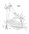
- a surface aircraft 11 with a built-in 3D measuring device 12 is shown.
- This comprises a laser rangefinder which determines the respective distance from the time of flight (time-of-flight, ToF) of the emitted laser radiation 19.
- the 3D measuring device further has a beam deflecting device which deflects the laser beams 19 normal to the direction of flight, so that the overflown terrain 13 is scanned line by line with a measuring beam fan 18.
- the respective geographic coordinates of the aircraft 11 are determined by a satellite navigation system (GPS).
- GPS satellite navigation system
- a so-called differential GPS is used, in which the navigation system receives not only signals from several satellites 15a, 15b,..., But also from a fixed station 16.
- the attitude (course, roll and pitch angle) is measured by means of a gyroscope 17. All these data are stored for each measuring point. In conjunction with the measured distance and the deflection angle of the deflection so that the geographical data of the measuring points are determined. In their entirety, these give a 3D data set or a corresponding point cloud of the terrain 13.
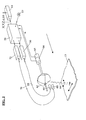
- Fig. 2 is shown schematically the structure of such an aircraft-based laser scanner.
- a central computer 56 which controls the individual components and links the distance values provided by the rangefinder with the scan angles, geographic coordinates and attitude angles and records these files.
- the output of the data sets can be done via a data carrier 57, for example a DVD.
- the central computer 56 drives a laser transmitter 30, which emits corresponding laser pulses.
- the laser radiation is fed through a fiber optic cable 58 to an optic 60.
- the rotating mirror pyramid 62 deflects the laser beam downwards and transversely to the direction of flight. In their entirety, the measuring beams form a fan of rays, which scans the area 13 like a line.
- the mirror pyramid is driven by a motor 64, which is controlled by the central computer 56. By an angle decoder 65 arranged on the motor shaft, the momentary adjustment of the mirror pyramid 62 is reported back to the computer 56.
- the laser radiation reflected from the target space is illuminated by the mirror pyramid 62 a lens 68 deflected and fed via a fiber optic cable 70 of the receiving stage 72.
- the echo pulses converted into electrical signals in the receiving stage are fed to the computer 56. From the running time (ToF) of the pulses, the corresponding distance values are calculated. These data are linked to the data supplied by the angle decoder 65, the DGPS 14 and the gyroscope 17. This data defines the geographic coordinates of each measurement point so that 3D terrain models can be calculated from the corresponding datasets.
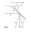
- the mirror pyramid is designed with mirror surfaces that enclose different angles with the axis of rotation.
- this principle is shown schematically: the axis of rotation of the mirror pyramid is denoted by 75, 3 mirror surfaces by 76 to 78.
- the mirror surface 76 includes the rotation axis at an angle of 45 °, 77 a larger, 78 a correspondingly smaller angle.
- the laser beam 79 is directed at the mirror surface 76 by 90 ° downwards (item 80).
- the mirror surface 78 of the measuring beam 81 is deflected forward, through the surface 77 to the rear (Pos. 82).
- When using a 3-sided mirror pyramid one forward rotation, one vertical downward and one backward directed fan beam is thus generated in one revolution.
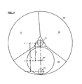
- a mirror pyramid 83 is shown in a projection in the direction of the axis of rotation 75.
- the individual surfaces 76 to 78 have different circumferential angles.
- the aperture of the laser beam 79 and the receiving beam 84 are shown.
- the optical axis of the laser transmitting beam has a much greater radial distance a from the axis of rotation 75 than the radial distance b of the optical axis of the receiving beam. This measure results in a significantly improved efficiency of the overall system.
- the Fig. 5 shows a variant of that in the Fig. 4 illustrated construction.
- the mirror pyramid 83 is the same in both figures.
- the receive beam is split into two beams 85 and 86, resulting in a slightly more favorable course of the energy of the reflected laser radiation during operation, which hits the receiving stage.
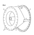
- a 3-sided mirror pyramid 86 is shown.
- the body of the pyramid is made of metal, for example of aluminum or magnesium or of corresponding alloys. Due to the asymmetrical design of the pyramid results in an uneven mass distribution, which can lead to disturbing vibrations especially at high speeds. It is therefore advantageous to balance the mirror pyramid dynamically.
- a plurality of holes 87 are provided in the base surface 88 of the pyramid 83, in which either weights can be filled, for example, pressed in lead weights, or which are drilled for local weight reduction.
- Such balance weights are alternatively or additionally provided in a further, arranged at an axial distance from the first plane second level, u.zw.
- the ring 89 preferably in the form of a ring 89, which is fastened with supports 90-92 to the mirror pyramid 83.
- the ring 89 also has a plurality of holes 87, which for Balance can be drilled individually or filled with weights.
- the supports 90-92 are, in order to reduce shadowing as far as possible, arranged in the extension or starting from the pyramid edges.
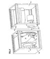
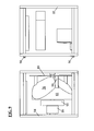
- a 3D measuring device in which the deflecting device with the rotating mirror pyramid 83 is arranged in a measuring head 94 which can be separated from the base device 93.
- the measuring head 94 comprises the rotating mirror pyramid 83 with the bearing, the associated drive motor 95, and an angle decoder 99.
- the measuring head 94 is connected to the base unit 93 with a multiple plug, not shown, and is controlled by a central computer arranged in the base unit 93. From the angle decoder 99 in the measuring head, the respective rotation angle is reported back to the computer.
- the base unit 93 in addition to the central computer and the laser rangefinder, including the associated evaluation device is housed.
- the measuring head 94 is oriented on the base unit 93.
- the two components 93 and 94 each have a window 97 and 98, which are aligned with each other in the assembled state.
- the windows 97 and 98 can have an optical effect and have a filter function and / or a corresponding refractive power.
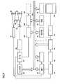
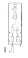
- the Fig. 10 schematically illustrates a laser rangefinder, as used in the device according to the invention.
- the beam deflection device by which the laser beam is deflected and the target area is scanned in a line.
- the laser rangefinder and the entire 3D measuring device are controlled by a micro-processor ( ⁇ P) 180.
- the rangefinder comprises a laser transmitter 181, which emits a laser pulse on a start pulse of the ⁇ P 180.
- the laser radiation is focused by an objective 182 to a preselected distance.
- the radiation reflected from objects in the target area is concentrated by a lens 183 onto a photosensitive diode 184, such as an avalanche diode.
- a small portion of the radiation emitted by the laser 181 radiation is fed directly to the receiving diode 184.
- This pulse which is received substantially simultaneously with the emission of the laser pulse, serves to determine the pulse transit time (time-of-flight, ToF) and thus the distance as a start signal for the time measurement.
- the output of the receiving diode 184 is amplified in an amplifier 186 and optionally filtered and finally digitized in an A / D converter 187.
- the A / D converter 187 and also the ⁇ P 180 are clocked by a pulse or clock generator 188.
- Output signals of the A / D converter 187 are fed to a counter stage 189, in which the number of clock pulses between the start pulse and the Receive pulse is determined. From the pulse number, the ToF is determined in the step 190 and, as a result, the distance between the range finder and the target is determined. However, the distance value calculated in this way has a relatively low accuracy.
- An advantage of this strategy is on the other hand, that the computational effort is very low and thus the computing time is minimal, so that the rangefinder can be operated at a very high clock rate.
- the ⁇ P 180 communicates with the other components of the system via a data bus 191.
- the software required to operate the ⁇ Ps 180 is stored in the program memory 192.
- the target area is detected only 2-dimensionally by the laser range finder in conjunction with the deflecting device, it is necessary for the acquisition of a 3D image to move the 3D surveying device in a translatory manner over the target area. For this it is necessary to define all degrees of freedom of the respective measuring beam in the room with high accuracy.
- To detect the geographical coordinates x, y and z and the course angle ⁇ is a satellite-based navigation system GPS. If, in addition to the various satellites, a fixed, terrestrial station is used for the measurement, an extremely high accuracy can be achieved. (Differential GPS - DGPS, block 193).
- the 3D surveying device can be arranged in the aircraft, for example on a gyro-stabilized platform, but in general it is more appropriate to derive the roll angle ⁇ , the pitch angle ⁇ and flight path angle y from a gyroscope (INS) 194.
- the position of the measuring beam is further defined by the beam deflecting device, namely in the device according to the invention in two different directions: for example, has the rotating mirror pyramid used for beam deflection, as in Fig. 3 schematically illustrated, three surfaces, each including a different angle with the axis of rotation, so depending on the corresponding angle sector, a scanning fan will be directed backwards, vertically downwards or forwards.
- the beam angle within the scanning fan determines the exact rotational angle ⁇ of the mirror pyramid.
- the respective rotation angle ⁇ is measured by an angle decoder 195 arranged on the rotation axis of the mirror pyramid, and by the ⁇ P 180 the fan angles and the beam angles within the compartments are determined.
- stage 196 the geographic coordinates of the measuring equipment and the various angles are linked to the simultaneously measured distance values and from this the geographical coordinates of the individual measuring points are determined. These data are stored in a data memory 197.
- the memory 197 can be connected to a PC on whose monitor 102 the measured terrain can then be checked on-line in a foresight on board the aircraft for completeness, etc.
- the stream of sampling pulses coming from the A / D converter 187 is fed to the stage 103, in which each individual measurement of the rangefinder is assigned the associated coordinates of the measuring device and the corresponding angle data.
- the data sets generated in this way are stored in a memory 104 and can be transferred to an external data carrier 106 via an interface 105 for off-line processing with high accuracy.
- the arithmetic unit 107 comprises a first data memory 108, in which the data coming from the data carrier 106 are stored.
- step 109 taking the pulse shape and amplitude into account, the temporal position of the corresponding pulse with respect to the scanner is determined from the sampling pulses.
- step 112 the time difference between the start and echo pulses and hence the distance to the target in question is calculated from these data with high accuracy. From this distance value, the geographic coordinates of the measuring device and the associated angle values, the geographical coordinates of the objects in the target area are defined.
- the corresponding measurement points describe a 3D data set or a point cloud. Since the data set or the corresponding point cloud is based on measurements from different directions, the resulting distance image is largely free of shadowing.
- the corresponding calculations are made by a ⁇ P 110 whose program memory is designated 111.
- a digital surface model (DSM) 113 can be generated, which can be further processed by known programs.
- the high-precision data processing can already be done on-line on board the aircraft, without having to accept a reduced measuring rate. In this case, it is unnecessary to generate a separate data record for the preview to control the measurement process.
- Planar mirrors are attached to this basic structure 100.
- the mirrors may be glued or bolted to the base structure 100. It may be appropriate to adjust the support points of the mirror adjustable. This construction is particularly suitable for irregular mirror pyramids or mirror prisms with different facet angles and / or a large facet number.
- a rangefinder can be used which emits a modulated laser beam, the transit time being determined from the phase relationship between the emitted and the echo signal.
- a rangefinder can be used which emits a modulated laser beam, the transit time being determined from the phase relationship between the emitted and the echo signal.
- the deflection device shown above with a mirror pyramid one with a mirror prism can also be used.
- aircraft-supported 3D surveying equipment is used again and again went out.
- these devices can be used with the same advantages in land vehicles, for example in rail vehicles. Advantages also arise when used on ships or boats, for the measurement of waterways and coastlines.
Landscapes
- Physics & Mathematics (AREA)
- Engineering & Computer Science (AREA)
- General Physics & Mathematics (AREA)
- Radar, Positioning & Navigation (AREA)
- Remote Sensing (AREA)
- Electromagnetism (AREA)
- Computer Networks & Wireless Communication (AREA)
- Optics & Photonics (AREA)
- Optical Radar Systems And Details Thereof (AREA)
- Length Measuring Devices By Optical Means (AREA)
Applications Claiming Priority (1)
| Application Number | Priority Date | Filing Date | Title |
|---|---|---|---|
| AT0138209A AT508562B1 (de) | 2009-09-02 | 2009-09-02 | 3-d vermessungseinrichtung |
Publications (3)
| Publication Number | Publication Date |
|---|---|
| EP2293013A2 true EP2293013A2 (fr) | 2011-03-09 |
| EP2293013A3 EP2293013A3 (fr) | 2012-09-19 |
| EP2293013B1 EP2293013B1 (fr) | 2014-10-08 |
Family
ID=43086306
Family Applications (1)
| Application Number | Title | Priority Date | Filing Date |
|---|---|---|---|
| EP10450139.0A Active EP2293013B1 (fr) | 2009-09-02 | 2010-09-02 | Dispositif de mesure laser en 3D |
Country Status (2)
| Country | Link |
|---|---|
| EP (1) | EP2293013B1 (fr) |
| AT (1) | AT508562B1 (fr) |
Cited By (19)
| Publication number | Priority date | Publication date | Assignee | Title |
|---|---|---|---|---|
| CN102518922A (zh) * | 2011-12-12 | 2012-06-27 | 中国科学院长春光学精密机械与物理研究所 | 碳纤维复合材料空间遥感器支撑架 |
| EP2562309A1 (fr) * | 2011-08-22 | 2013-02-27 | Joseph Vögele AG | Finisseuse de route dotée d'un dispositif de mesure |
| US20130077083A1 (en) * | 2011-09-22 | 2013-03-28 | Shuichi Suzuki | Optical beam scanner and laser radar unit |
| JP2016070974A (ja) * | 2014-09-26 | 2016-05-09 | 株式会社デンソー | レーザ照射制御装置 |
| AT517701A4 (de) * | 2016-04-15 | 2017-04-15 | Riegl Laser Measurement Systems Gmbh | Laserscanner |
| JPWO2017065048A1 (ja) * | 2015-10-16 | 2018-08-02 | コニカミノルタ株式会社 | 光走査型の対象物検出装置 |
| CN108840244A (zh) * | 2017-12-20 | 2018-11-20 | 江苏耐维思通科技股份有限公司 | 一种自动吊装的智能行车控制组件 |
| CN109254286A (zh) * | 2018-11-13 | 2019-01-22 | 武汉海达数云技术有限公司 | 机载激光雷达光学扫描装置 |
| CN109444842A (zh) * | 2019-01-04 | 2019-03-08 | 北京环境特性研究所 | 一种目标电磁散射特性数据重构方法和装置 |
| CN110100189A (zh) * | 2016-11-07 | 2019-08-06 | 布莱克菲尔德公司 | 具有至少两根纤维的纤维扫描器 |
| CN111141744A (zh) * | 2019-12-31 | 2020-05-12 | 广州维思车用部件有限公司 | 一种镜片检测装置 |
| EP3792653A1 (fr) | 2019-09-12 | 2021-03-17 | Riegl Laser Measurement Systems GmbH | Lecteur laser |
| CN113125439A (zh) * | 2019-12-31 | 2021-07-16 | 南京璟一机器人工程技术有限公司 | 一种弹簧端面检测系统及其检测方法 |
| CN113238240A (zh) * | 2021-05-15 | 2021-08-10 | 李学刚 | 一种房产测绘用手持测距仪 |
| US20210364605A1 (en) * | 2020-05-19 | 2021-11-25 | Gm Cruise Holdings Llc | Polygon scanning mirror for lidar beam scanning |
| CN115113175A (zh) * | 2022-06-23 | 2022-09-27 | 青岛华航环境科技有限责任公司 | 一种可替换扫描模块的多用途大气边界层垂直风廓线激光雷达 |
| EP4063915A1 (fr) * | 2021-03-25 | 2022-09-28 | RIEGL Laser Measurement Systems GmbH | Dispositif de mesure d'un environnement |
| CN115184742A (zh) * | 2022-05-06 | 2022-10-14 | 宁波送变电建设有限公司 | 一种用于变电站的光学监测角测量仪器 |
| EP4428566A1 (fr) * | 2023-03-09 | 2024-09-11 | RIEGL Laser Measurement Systems GmbH | Scanner laser pour balayer un environnement autour d'un axe |
Families Citing this family (1)
| Publication number | Priority date | Publication date | Assignee | Title |
|---|---|---|---|---|
| WO2021023254A1 (fr) * | 2019-08-07 | 2021-02-11 | 深圳市速腾聚创科技有限公司 | Radar laser et dispositif de détection intelligent |
Family Cites Families (4)
| Publication number | Priority date | Publication date | Assignee | Title |
|---|---|---|---|---|
| DE3217785C1 (de) * | 1982-05-12 | 1983-12-15 | Messerschmitt-Bölkow-Blohm GmbH, 8000 München | Optisch-mechanischer Abtaster |
| JP3908297B2 (ja) * | 1996-03-19 | 2007-04-25 | 株式会社トプコン | レーザ測量機 |
| AT413452B (de) * | 2003-11-18 | 2006-03-15 | Riegl Laser Measurement Sys | Einrichtung zur aufnahme eines objektraumes |
| JP2005291787A (ja) * | 2004-03-31 | 2005-10-20 | Denso Corp | 距離検出装置 |
-
2009
- 2009-09-02 AT AT0138209A patent/AT508562B1/de active
-
2010
- 2010-09-02 EP EP10450139.0A patent/EP2293013B1/fr active Active
Non-Patent Citations (1)
| Title |
|---|
| None |
Cited By (35)
| Publication number | Priority date | Publication date | Assignee | Title |
|---|---|---|---|---|
| EP2562309A1 (fr) * | 2011-08-22 | 2013-02-27 | Joseph Vögele AG | Finisseuse de route dotée d'un dispositif de mesure |
| US9290894B2 (en) | 2011-08-22 | 2016-03-22 | Joseph Vogele Ag | Road paver with measuring device |
| US20130077083A1 (en) * | 2011-09-22 | 2013-03-28 | Shuichi Suzuki | Optical beam scanner and laser radar unit |
| EP2573580A3 (fr) * | 2011-09-22 | 2013-05-01 | Ricoh Company, Ltd. | Dispositif de balayage de faisceau optique et unité de radar laser |
| US8773644B2 (en) | 2011-09-22 | 2014-07-08 | Ricoh Company, Ltd. | Optical beam scanner and laser radar unit |
| CN102518922A (zh) * | 2011-12-12 | 2012-06-27 | 中国科学院长春光学精密机械与物理研究所 | 碳纤维复合材料空间遥感器支撑架 |
| JP2016070974A (ja) * | 2014-09-26 | 2016-05-09 | 株式会社デンソー | レーザ照射制御装置 |
| JPWO2017065048A1 (ja) * | 2015-10-16 | 2018-08-02 | コニカミノルタ株式会社 | 光走査型の対象物検出装置 |
| EP3364229A4 (fr) * | 2015-10-16 | 2018-10-31 | Konica Minolta, Inc. | Dispositif de détection d'objet de type à balayage optique |
| AT517701B1 (de) * | 2016-04-15 | 2017-04-15 | Riegl Laser Measurement Systems Gmbh | Laserscanner |
| WO2017177246A1 (fr) * | 2016-04-15 | 2017-10-19 | Riegl Laser Measurement Systems Gmbh | Scanner laser |
| US11073616B2 (en) | 2016-04-15 | 2021-07-27 | Riegl Laser Measurement Systems Gmbh | Laser scanner |
| AT517701A4 (de) * | 2016-04-15 | 2017-04-15 | Riegl Laser Measurement Systems Gmbh | Laserscanner |
| CN110100189A (zh) * | 2016-11-07 | 2019-08-06 | 布莱克菲尔德公司 | 具有至少两根纤维的纤维扫描器 |
| CN108840244A (zh) * | 2017-12-20 | 2018-11-20 | 江苏耐维思通科技股份有限公司 | 一种自动吊装的智能行车控制组件 |
| CN109254286A (zh) * | 2018-11-13 | 2019-01-22 | 武汉海达数云技术有限公司 | 机载激光雷达光学扫描装置 |
| CN109254286B (zh) * | 2018-11-13 | 2024-05-28 | 武汉海达数云技术有限公司 | 机载激光雷达光学扫描装置 |
| CN109444842A (zh) * | 2019-01-04 | 2019-03-08 | 北京环境特性研究所 | 一种目标电磁散射特性数据重构方法和装置 |
| CN109444842B (zh) * | 2019-01-04 | 2020-09-25 | 北京环境特性研究所 | 一种目标电磁散射特性数据重构方法和装置 |
| CN114365006A (zh) * | 2019-09-12 | 2022-04-15 | 雷格雷射测量系统公司 | 激光扫描仪 |
| WO2021047846A1 (fr) | 2019-09-12 | 2021-03-18 | Riegl Laser Measurement Systems Gmbh | Scanner laser |
| US12392872B2 (en) | 2019-09-12 | 2025-08-19 | Riegl Laser Measurement Systems Gmbh | Laser scanner |
| EP3792653A1 (fr) | 2019-09-12 | 2021-03-17 | Riegl Laser Measurement Systems GmbH | Lecteur laser |
| CN111141744B (zh) * | 2019-12-31 | 2023-01-31 | 广州维思车用部件有限公司 | 一种镜片检测装置 |
| CN113125439A (zh) * | 2019-12-31 | 2021-07-16 | 南京璟一机器人工程技术有限公司 | 一种弹簧端面检测系统及其检测方法 |
| CN111141744A (zh) * | 2019-12-31 | 2020-05-12 | 广州维思车用部件有限公司 | 一种镜片检测装置 |
| CN113125439B (zh) * | 2019-12-31 | 2023-11-07 | 南京景曜智能科技有限公司 | 一种弹簧端面检测系统及其检测方法 |
| US20210364605A1 (en) * | 2020-05-19 | 2021-11-25 | Gm Cruise Holdings Llc | Polygon scanning mirror for lidar beam scanning |
| US12055660B2 (en) * | 2020-05-19 | 2024-08-06 | Gm Cruise Holdings Llc | Polygon scanning mirror for lidar beam scanning |
| EP4063915A1 (fr) * | 2021-03-25 | 2022-09-28 | RIEGL Laser Measurement Systems GmbH | Dispositif de mesure d'un environnement |
| CN113238240A (zh) * | 2021-05-15 | 2021-08-10 | 李学刚 | 一种房产测绘用手持测距仪 |
| CN115184742A (zh) * | 2022-05-06 | 2022-10-14 | 宁波送变电建设有限公司 | 一种用于变电站的光学监测角测量仪器 |
| CN115184742B (zh) * | 2022-05-06 | 2024-06-04 | 宁波送变电建设有限公司 | 一种用于变电站的光学监测角测量仪器 |
| CN115113175A (zh) * | 2022-06-23 | 2022-09-27 | 青岛华航环境科技有限责任公司 | 一种可替换扫描模块的多用途大气边界层垂直风廓线激光雷达 |
| EP4428566A1 (fr) * | 2023-03-09 | 2024-09-11 | RIEGL Laser Measurement Systems GmbH | Scanner laser pour balayer un environnement autour d'un axe |
Also Published As
| Publication number | Publication date |
|---|---|
| EP2293013B1 (fr) | 2014-10-08 |
| AT508562B1 (de) | 2011-02-15 |
| EP2293013A3 (fr) | 2012-09-19 |
| AT508562A4 (de) | 2011-02-15 |
Similar Documents
| Publication | Publication Date | Title |
|---|---|---|
| EP2293013B1 (fr) | Dispositif de mesure laser en 3D | |
| DE102004050682B4 (de) | Einrichtung zur Aufnahme eines Objektraumes | |
| DE3922086C1 (fr) | ||
| AT411299B (de) | Verfahren zur aufnahme eines objektraumes | |
| AT412028B (de) | Einrichtung zur aufnahme eines objektraumes | |
| DE69419102T2 (de) | Hindernissvermeidungssystem für Hubschrauber und Flugzeuge | |
| AT509180B1 (de) | Optoelektronisches messsystem | |
| EP1321777B1 (fr) | Procédé de prise de vues d'un espace objet | |
| EP0634668B1 (fr) | Dispositif radar pour l'avertissement d'obstacle | |
| DE69005106T2 (de) | Anordnung zum erstellen oder bestimmen der ortung eines messpunktes. | |
| DE3887667T2 (de) | Radioelektrischer Sensor zur Erstellung einer radioelektrischen Karte einer Landschaft. | |
| DE3731037A1 (de) | Laser-abbildungssystem mit detektorzeile | |
| EP0406879B1 (fr) | Méthode d'extraction d'erreurs de mouvement d'un porteur transportant un système radar d'imagerie cohérent à partir de données radar brutes et dispositif pour la mise en oeuvre de ce procédé | |
| EP0757259A1 (fr) | Dispositif de compensation d'erreur de mouvement pour radar à ouverture synthétique à base d'antennes tournantes dans un hélicoptère | |
| DE102005015914A1 (de) | Kombinierte Laser-Höhen- und Bodengeschwindigkeits-Messvorrichtung | |
| EP3443381B1 (fr) | Scanner laser | |
| DE102011121115B4 (de) | Laser-Scanner und Verfahren zur Vermessung von Zielräumen | |
| DE10341893B4 (de) | Verfahren zur Verringerung des Dopplerzentroids bei einem kohärenten impuls-Radarsystem sowie Verwendung des Verfahrens | |
| WO2019233701A1 (fr) | Procédé et dispositif pour la mesure de vibrations d'un objet par l'utilisation d'un drone | |
| EP1329739A2 (fr) | Dispositif de prise de vues d'un espace objet | |
| DE2850743C3 (de) | Verfahren und Vorrichtung zur Messung der Abweichung des Sendestrahls von der optischen Achse des Empfangsteleskops bei einem Lidargerät | |
| DE102014216368B4 (de) | Mehrarmiges lidar-system | |
| AT512782B1 (de) | Opto-elektronisches Vermessungsverfahren | |
| EP3938804B1 (fr) | Dispositif de balayage laser et procédé de mesure tridimensionnelle d'une scène à une distance élevée | |
| EP0195056A1 (fr) | Systeme optique pour la compensation du mouvement dans les scanners ligne par ligne. |
Legal Events
| Date | Code | Title | Description |
|---|---|---|---|
| PUAI | Public reference made under article 153(3) epc to a published international application that has entered the european phase |
Free format text: ORIGINAL CODE: 0009012 |
|
| AK | Designated contracting states |
Kind code of ref document: A2 Designated state(s): AL AT BE BG CH CY CZ DE DK EE ES FI FR GB GR HR HU IE IS IT LI LT LU LV MC MK MT NL NO PL PT RO SE SI SK SM TR |
|
| AX | Request for extension of the european patent |
Extension state: BA ME RS |
|
| PUAL | Search report despatched |
Free format text: ORIGINAL CODE: 0009013 |
|
| AK | Designated contracting states |
Kind code of ref document: A3 Designated state(s): AL AT BE BG CH CY CZ DE DK EE ES FI FR GB GR HR HU IE IS IT LI LT LU LV MC MK MT NL NO PL PT RO SE SI SK SM TR |
|
| AX | Request for extension of the european patent |
Extension state: BA ME RS |
|
| RIC1 | Information provided on ipc code assigned before grant |
Ipc: G01S 17/10 20060101ALI20120815BHEP Ipc: G01S 17/89 20060101ALI20120815BHEP Ipc: G01S 17/42 20060101ALI20120815BHEP Ipc: G02B 26/10 20060101ALI20120815BHEP Ipc: G02B 5/09 20060101ALI20120815BHEP Ipc: G02B 26/12 20060101ALI20120815BHEP Ipc: G01C 15/00 20060101AFI20120815BHEP |
|
| 17P | Request for examination filed |
Effective date: 20121218 |
|
| 17Q | First examination report despatched |
Effective date: 20130322 |
|
| REG | Reference to a national code |
Ref country code: DE Ref legal event code: R079 Ref document number: 502010008026 Country of ref document: DE Free format text: PREVIOUS MAIN CLASS: G01C0015000000 Ipc: G01S0007481000 |
|
| RIC1 | Information provided on ipc code assigned before grant |
Ipc: G02B 26/12 20060101ALI20131105BHEP Ipc: G01S 17/42 20060101ALI20131105BHEP Ipc: G02B 5/09 20060101ALI20131105BHEP Ipc: G01C 15/00 20060101ALI20131105BHEP Ipc: G01S 17/10 20060101ALI20131105BHEP Ipc: G01S 17/89 20060101ALI20131105BHEP Ipc: G02B 26/10 20060101ALI20131105BHEP Ipc: G01S 7/481 20060101AFI20131105BHEP |
|
| GRAP | Despatch of communication of intention to grant a patent |
Free format text: ORIGINAL CODE: EPIDOSNIGR1 |
|
| INTG | Intention to grant announced |
Effective date: 20140521 |
|
| GRAS | Grant fee paid |
Free format text: ORIGINAL CODE: EPIDOSNIGR3 |
|
| GRAA | (expected) grant |
Free format text: ORIGINAL CODE: 0009210 |
|
| AK | Designated contracting states |
Kind code of ref document: B1 Designated state(s): AL AT BE BG CH CY CZ DE DK EE ES FI FR GB GR HR HU IE IS IT LI LT LU LV MC MK MT NL NO PL PT RO SE SI SK SM TR |
|
| REG | Reference to a national code |
Ref country code: GB Ref legal event code: FG4D Free format text: NOT ENGLISH |
|
| REG | Reference to a national code |
Ref country code: AT Ref legal event code: REF Ref document number: 690916 Country of ref document: AT Kind code of ref document: T Effective date: 20141015 Ref country code: CH Ref legal event code: EP |
|
| REG | Reference to a national code |
Ref country code: IE Ref legal event code: FG4D Free format text: LANGUAGE OF EP DOCUMENT: GERMAN |
|
| REG | Reference to a national code |
Ref country code: DE Ref legal event code: R096 Ref document number: 502010008026 Country of ref document: DE Effective date: 20141120 |
|
| REG | Reference to a national code |
Ref country code: CH Ref legal event code: NV Representative=s name: PATWIL AG, CH |
|
| REG | Reference to a national code |
Ref country code: NL Ref legal event code: VDEP Effective date: 20141008 |
|
| REG | Reference to a national code |
Ref country code: LT Ref legal event code: MG4D |
|
| PG25 | Lapsed in a contracting state [announced via postgrant information from national office to epo] |
Ref country code: NL Free format text: LAPSE BECAUSE OF FAILURE TO SUBMIT A TRANSLATION OF THE DESCRIPTION OR TO PAY THE FEE WITHIN THE PRESCRIBED TIME-LIMIT Effective date: 20141008 |
|
| PG25 | Lapsed in a contracting state [announced via postgrant information from national office to epo] |
Ref country code: FI Free format text: LAPSE BECAUSE OF FAILURE TO SUBMIT A TRANSLATION OF THE DESCRIPTION OR TO PAY THE FEE WITHIN THE PRESCRIBED TIME-LIMIT Effective date: 20141008 Ref country code: LT Free format text: LAPSE BECAUSE OF FAILURE TO SUBMIT A TRANSLATION OF THE DESCRIPTION OR TO PAY THE FEE WITHIN THE PRESCRIBED TIME-LIMIT Effective date: 20141008 Ref country code: IS Free format text: LAPSE BECAUSE OF FAILURE TO SUBMIT A TRANSLATION OF THE DESCRIPTION OR TO PAY THE FEE WITHIN THE PRESCRIBED TIME-LIMIT Effective date: 20150208 Ref country code: NO Free format text: LAPSE BECAUSE OF FAILURE TO SUBMIT A TRANSLATION OF THE DESCRIPTION OR TO PAY THE FEE WITHIN THE PRESCRIBED TIME-LIMIT Effective date: 20150108 Ref country code: ES Free format text: LAPSE BECAUSE OF FAILURE TO SUBMIT A TRANSLATION OF THE DESCRIPTION OR TO PAY THE FEE WITHIN THE PRESCRIBED TIME-LIMIT Effective date: 20141008 Ref country code: PT Free format text: LAPSE BECAUSE OF FAILURE TO SUBMIT A TRANSLATION OF THE DESCRIPTION OR TO PAY THE FEE WITHIN THE PRESCRIBED TIME-LIMIT Effective date: 20150209 |
|
| PG25 | Lapsed in a contracting state [announced via postgrant information from national office to epo] |
Ref country code: SE Free format text: LAPSE BECAUSE OF FAILURE TO SUBMIT A TRANSLATION OF THE DESCRIPTION OR TO PAY THE FEE WITHIN THE PRESCRIBED TIME-LIMIT Effective date: 20141008 Ref country code: CY Free format text: LAPSE BECAUSE OF FAILURE TO SUBMIT A TRANSLATION OF THE DESCRIPTION OR TO PAY THE FEE WITHIN THE PRESCRIBED TIME-LIMIT Effective date: 20141008 Ref country code: PL Free format text: LAPSE BECAUSE OF FAILURE TO SUBMIT A TRANSLATION OF THE DESCRIPTION OR TO PAY THE FEE WITHIN THE PRESCRIBED TIME-LIMIT Effective date: 20141008 Ref country code: LV Free format text: LAPSE BECAUSE OF FAILURE TO SUBMIT A TRANSLATION OF THE DESCRIPTION OR TO PAY THE FEE WITHIN THE PRESCRIBED TIME-LIMIT Effective date: 20141008 Ref country code: HR Free format text: LAPSE BECAUSE OF FAILURE TO SUBMIT A TRANSLATION OF THE DESCRIPTION OR TO PAY THE FEE WITHIN THE PRESCRIBED TIME-LIMIT Effective date: 20141008 Ref country code: GR Free format text: LAPSE BECAUSE OF FAILURE TO SUBMIT A TRANSLATION OF THE DESCRIPTION OR TO PAY THE FEE WITHIN THE PRESCRIBED TIME-LIMIT Effective date: 20150109 |
|
| REG | Reference to a national code |
Ref country code: DE Ref legal event code: R097 Ref document number: 502010008026 Country of ref document: DE |
|
| PG25 | Lapsed in a contracting state [announced via postgrant information from national office to epo] |
Ref country code: DK Free format text: LAPSE BECAUSE OF FAILURE TO SUBMIT A TRANSLATION OF THE DESCRIPTION OR TO PAY THE FEE WITHIN THE PRESCRIBED TIME-LIMIT Effective date: 20141008 Ref country code: SK Free format text: LAPSE BECAUSE OF FAILURE TO SUBMIT A TRANSLATION OF THE DESCRIPTION OR TO PAY THE FEE WITHIN THE PRESCRIBED TIME-LIMIT Effective date: 20141008 Ref country code: CZ Free format text: LAPSE BECAUSE OF FAILURE TO SUBMIT A TRANSLATION OF THE DESCRIPTION OR TO PAY THE FEE WITHIN THE PRESCRIBED TIME-LIMIT Effective date: 20141008 Ref country code: EE Free format text: LAPSE BECAUSE OF FAILURE TO SUBMIT A TRANSLATION OF THE DESCRIPTION OR TO PAY THE FEE WITHIN THE PRESCRIBED TIME-LIMIT Effective date: 20141008 Ref country code: RO Free format text: LAPSE BECAUSE OF FAILURE TO SUBMIT A TRANSLATION OF THE DESCRIPTION OR TO PAY THE FEE WITHIN THE PRESCRIBED TIME-LIMIT Effective date: 20141008 |
|
| PLBE | No opposition filed within time limit |
Free format text: ORIGINAL CODE: 0009261 |
|
| STAA | Information on the status of an ep patent application or granted ep patent |
Free format text: STATUS: NO OPPOSITION FILED WITHIN TIME LIMIT |
|
| PG25 | Lapsed in a contracting state [announced via postgrant information from national office to epo] |
Ref country code: IT Free format text: LAPSE BECAUSE OF FAILURE TO SUBMIT A TRANSLATION OF THE DESCRIPTION OR TO PAY THE FEE WITHIN THE PRESCRIBED TIME-LIMIT Effective date: 20141008 |
|
| 26N | No opposition filed |
Effective date: 20150709 |
|
| PG25 | Lapsed in a contracting state [announced via postgrant information from national office to epo] |
Ref country code: SI Free format text: LAPSE BECAUSE OF FAILURE TO SUBMIT A TRANSLATION OF THE DESCRIPTION OR TO PAY THE FEE WITHIN THE PRESCRIBED TIME-LIMIT Effective date: 20141008 |
|
| PG25 | Lapsed in a contracting state [announced via postgrant information from national office to epo] |
Ref country code: LU Free format text: LAPSE BECAUSE OF FAILURE TO SUBMIT A TRANSLATION OF THE DESCRIPTION OR TO PAY THE FEE WITHIN THE PRESCRIBED TIME-LIMIT Effective date: 20150902 Ref country code: MC Free format text: LAPSE BECAUSE OF FAILURE TO SUBMIT A TRANSLATION OF THE DESCRIPTION OR TO PAY THE FEE WITHIN THE PRESCRIBED TIME-LIMIT Effective date: 20141008 |
|
| REG | Reference to a national code |
Ref country code: FR Ref legal event code: ST Effective date: 20160531 |
|
| PG25 | Lapsed in a contracting state [announced via postgrant information from national office to epo] |
Ref country code: IE Free format text: LAPSE BECAUSE OF NON-PAYMENT OF DUE FEES Effective date: 20150902 |
|
| PG25 | Lapsed in a contracting state [announced via postgrant information from national office to epo] |
Ref country code: FR Free format text: LAPSE BECAUSE OF NON-PAYMENT OF DUE FEES Effective date: 20150930 |
|
| REG | Reference to a national code |
Ref country code: AT Ref legal event code: MM01 Ref document number: 690916 Country of ref document: AT Kind code of ref document: T Effective date: 20150902 |
|
| PG25 | Lapsed in a contracting state [announced via postgrant information from national office to epo] |
Ref country code: AT Free format text: LAPSE BECAUSE OF NON-PAYMENT OF DUE FEES Effective date: 20150902 |
|
| PG25 | Lapsed in a contracting state [announced via postgrant information from national office to epo] |
Ref country code: MT Free format text: LAPSE BECAUSE OF FAILURE TO SUBMIT A TRANSLATION OF THE DESCRIPTION OR TO PAY THE FEE WITHIN THE PRESCRIBED TIME-LIMIT Effective date: 20141008 |
|
| PG25 | Lapsed in a contracting state [announced via postgrant information from national office to epo] |
Ref country code: HU Free format text: LAPSE BECAUSE OF FAILURE TO SUBMIT A TRANSLATION OF THE DESCRIPTION OR TO PAY THE FEE WITHIN THE PRESCRIBED TIME-LIMIT; INVALID AB INITIO Effective date: 20100902 Ref country code: SM Free format text: LAPSE BECAUSE OF FAILURE TO SUBMIT A TRANSLATION OF THE DESCRIPTION OR TO PAY THE FEE WITHIN THE PRESCRIBED TIME-LIMIT Effective date: 20141008 Ref country code: BG Free format text: LAPSE BECAUSE OF FAILURE TO SUBMIT A TRANSLATION OF THE DESCRIPTION OR TO PAY THE FEE WITHIN THE PRESCRIBED TIME-LIMIT Effective date: 20141008 |
|
| PG25 | Lapsed in a contracting state [announced via postgrant information from national office to epo] |
Ref country code: BE Free format text: LAPSE BECAUSE OF NON-PAYMENT OF DUE FEES Effective date: 20150930 |
|
| PG25 | Lapsed in a contracting state [announced via postgrant information from national office to epo] |
Ref country code: TR Free format text: LAPSE BECAUSE OF FAILURE TO SUBMIT A TRANSLATION OF THE DESCRIPTION OR TO PAY THE FEE WITHIN THE PRESCRIBED TIME-LIMIT Effective date: 20141008 |
|
| REG | Reference to a national code |
Ref country code: CH Ref legal event code: NV Representative=s name: HEPP WENGER RYFFEL AG, CH |
|
| PG25 | Lapsed in a contracting state [announced via postgrant information from national office to epo] |
Ref country code: MK Free format text: LAPSE BECAUSE OF FAILURE TO SUBMIT A TRANSLATION OF THE DESCRIPTION OR TO PAY THE FEE WITHIN THE PRESCRIBED TIME-LIMIT Effective date: 20141008 |
|
| PG25 | Lapsed in a contracting state [announced via postgrant information from national office to epo] |
Ref country code: AL Free format text: LAPSE BECAUSE OF FAILURE TO SUBMIT A TRANSLATION OF THE DESCRIPTION OR TO PAY THE FEE WITHIN THE PRESCRIBED TIME-LIMIT Effective date: 20141008 |
|
| P01 | Opt-out of the competence of the unified patent court (upc) registered |
Effective date: 20230601 |
|
| REG | Reference to a national code |
Ref country code: CH Ref legal event code: U11 Free format text: ST27 STATUS EVENT CODE: U-0-0-U10-U11 (AS PROVIDED BY THE NATIONAL OFFICE) Effective date: 20251001 |
|
| PGFP | Annual fee paid to national office [announced via postgrant information from national office to epo] |
Ref country code: DE Payment date: 20250919 Year of fee payment: 16 |
|
| PGFP | Annual fee paid to national office [announced via postgrant information from national office to epo] |
Ref country code: GB Payment date: 20250923 Year of fee payment: 16 |
|
| PGFP | Annual fee paid to national office [announced via postgrant information from national office to epo] |
Ref country code: CH Payment date: 20251001 Year of fee payment: 16 |