EP2293050A1 - Appareil de chauffage pour inspection par rayons x - Google Patents
Appareil de chauffage pour inspection par rayons x Download PDFInfo
- Publication number
- EP2293050A1 EP2293050A1 EP10761511A EP10761511A EP2293050A1 EP 2293050 A1 EP2293050 A1 EP 2293050A1 EP 10761511 A EP10761511 A EP 10761511A EP 10761511 A EP10761511 A EP 10761511A EP 2293050 A1 EP2293050 A1 EP 2293050A1
- Authority
- EP
- European Patent Office
- Prior art keywords
- heating apparatus
- ray inspection
- ray
- heating
- sample
- Prior art date
- Legal status (The legal status is an assumption and is not a legal conclusion. Google has not performed a legal analysis and makes no representation as to the accuracy of the status listed.)
- Granted
Links
Images






Classifications
-
- H—ELECTRICITY
- H05—ELECTRIC TECHNIQUES NOT OTHERWISE PROVIDED FOR
- H05B—ELECTRIC HEATING; ELECTRIC LIGHT SOURCES NOT OTHERWISE PROVIDED FOR; CIRCUIT ARRANGEMENTS FOR ELECTRIC LIGHT SOURCES, IN GENERAL
- H05B3/00—Ohmic-resistance heating
- H05B3/20—Heating elements having extended surface area substantially in a two-dimensional [2D] plane, e.g. plate-heater
- H05B3/22—Heating elements having extended surface area substantially in a two-dimensional [2D] plane, e.g. plate-heater non-flexible
- H05B3/28—Heating elements having extended surface area substantially in a two-dimensional [2D] plane, e.g. plate-heater non-flexible heating conductor embedded in insulating material
- H05B3/283—Heating elements having extended surface area substantially in a two-dimensional [2D] plane, e.g. plate-heater non-flexible heating conductor embedded in insulating material the insulating material being an inorganic material, e.g. ceramic
-
- H—ELECTRICITY
- H05—ELECTRIC TECHNIQUES NOT OTHERWISE PROVIDED FOR
- H05B—ELECTRIC HEATING; ELECTRIC LIGHT SOURCES NOT OTHERWISE PROVIDED FOR; CIRCUIT ARRANGEMENTS FOR ELECTRIC LIGHT SOURCES, IN GENERAL
- H05B3/00—Ohmic-resistance heating
- H05B3/20—Heating elements having extended surface area substantially in a two-dimensional [2D] plane, e.g. plate-heater
- H05B3/22—Heating elements having extended surface area substantially in a two-dimensional [2D] plane, e.g. plate-heater non-flexible
- H05B3/26—Heating elements having extended surface area substantially in a two-dimensional [2D] plane, e.g. plate-heater non-flexible heating conductor mounted on insulating base
- H05B3/262—Heating elements having extended surface area substantially in a two-dimensional [2D] plane, e.g. plate-heater non-flexible heating conductor mounted on insulating base the insulating base being an insulated metal plate
-
- G—PHYSICS
- G01—MEASURING; TESTING
- G01N—INVESTIGATING OR ANALYSING MATERIALS BY DETERMINING THEIR CHEMICAL OR PHYSICAL PROPERTIES
- G01N23/00—Investigating or analysing materials by the use of wave or particle radiation, e.g. X-rays or neutrons, not covered by groups G01N3/00 – G01N17/00, G01N21/00 or G01N22/00
- G01N23/02—Investigating or analysing materials by the use of wave or particle radiation, e.g. X-rays or neutrons, not covered by groups G01N3/00 – G01N17/00, G01N21/00 or G01N22/00 by transmitting the radiation through the material
-
- G—PHYSICS
- G01—MEASURING; TESTING
- G01N—INVESTIGATING OR ANALYSING MATERIALS BY DETERMINING THEIR CHEMICAL OR PHYSICAL PROPERTIES
- G01N23/00—Investigating or analysing materials by the use of wave or particle radiation, e.g. X-rays or neutrons, not covered by groups G01N3/00 – G01N17/00, G01N21/00 or G01N22/00
- G01N23/20—Investigating or analysing materials by the use of wave or particle radiation, e.g. X-rays or neutrons, not covered by groups G01N3/00 – G01N17/00, G01N21/00 or G01N22/00 by using diffraction of the radiation by the materials, e.g. for investigating crystal structure; by using scattering of the radiation by the materials, e.g. for investigating non-crystalline materials; by using reflection of the radiation by the materials
- G01N23/20008—Constructional details of analysers, e.g. characterised by X-ray source, detector or optical system; Accessories therefor; Preparing specimens therefor
- G01N23/20025—Sample holders or supports therefor
- G01N23/20033—Sample holders or supports therefor provided with temperature control or heating means
-
- H—ELECTRICITY
- H05—ELECTRIC TECHNIQUES NOT OTHERWISE PROVIDED FOR
- H05B—ELECTRIC HEATING; ELECTRIC LIGHT SOURCES NOT OTHERWISE PROVIDED FOR; CIRCUIT ARRANGEMENTS FOR ELECTRIC LIGHT SOURCES, IN GENERAL
- H05B2203/00—Aspects relating to Ohmic resistive heating covered by group H05B3/00
- H05B2203/002—Heaters using a particular layout for the resistive material or resistive elements
-
- H—ELECTRICITY
- H05—ELECTRIC TECHNIQUES NOT OTHERWISE PROVIDED FOR
- H05B—ELECTRIC HEATING; ELECTRIC LIGHT SOURCES NOT OTHERWISE PROVIDED FOR; CIRCUIT ARRANGEMENTS FOR ELECTRIC LIGHT SOURCES, IN GENERAL
- H05B2203/00—Aspects relating to Ohmic resistive heating covered by group H05B3/00
- H05B2203/002—Heaters using a particular layout for the resistive material or resistive elements
- H05B2203/003—Heaters using a particular layout for the resistive material or resistive elements using serpentine layout
-
- H—ELECTRICITY
- H05—ELECTRIC TECHNIQUES NOT OTHERWISE PROVIDED FOR
- H05B—ELECTRIC HEATING; ELECTRIC LIGHT SOURCES NOT OTHERWISE PROVIDED FOR; CIRCUIT ARRANGEMENTS FOR ELECTRIC LIGHT SOURCES, IN GENERAL
- H05B2203/00—Aspects relating to Ohmic resistive heating covered by group H05B3/00
- H05B2203/002—Heaters using a particular layout for the resistive material or resistive elements
- H05B2203/004—Heaters using a particular layout for the resistive material or resistive elements using zigzag layout
-
- H—ELECTRICITY
- H05—ELECTRIC TECHNIQUES NOT OTHERWISE PROVIDED FOR
- H05B—ELECTRIC HEATING; ELECTRIC LIGHT SOURCES NOT OTHERWISE PROVIDED FOR; CIRCUIT ARRANGEMENTS FOR ELECTRIC LIGHT SOURCES, IN GENERAL
- H05B2203/00—Aspects relating to Ohmic resistive heating covered by group H05B3/00
- H05B2203/017—Manufacturing methods or apparatus for heaters
-
- H—ELECTRICITY
- H05—ELECTRIC TECHNIQUES NOT OTHERWISE PROVIDED FOR
- H05B—ELECTRIC HEATING; ELECTRIC LIGHT SOURCES NOT OTHERWISE PROVIDED FOR; CIRCUIT ARRANGEMENTS FOR ELECTRIC LIGHT SOURCES, IN GENERAL
- H05B2203/00—Aspects relating to Ohmic resistive heating covered by group H05B3/00
- H05B2203/022—Heaters specially adapted for heating gaseous material
-
- H—ELECTRICITY
- H05—ELECTRIC TECHNIQUES NOT OTHERWISE PROVIDED FOR
- H05B—ELECTRIC HEATING; ELECTRIC LIGHT SOURCES NOT OTHERWISE PROVIDED FOR; CIRCUIT ARRANGEMENTS FOR ELECTRIC LIGHT SOURCES, IN GENERAL
- H05B2203/00—Aspects relating to Ohmic resistive heating covered by group H05B3/00
- H05B2203/033—Heater including particular mechanical reinforcing means
Definitions
- the present invention relates to a heating apparatus for X-ray inspection and, in particular, to a heating apparatus for X-ray inspection which is effectively used in analyzing a cause of defective generation at a solder joint part and capable of heating an object to be examined such as a sample to a target temperature or heating it according to a predetermined profile, thereby observing and recording the change in the state in real time.
- an X-ray inspection at high temperature capable of observing a change in crystalline structure or a change in the melted state by heating a sample to high temperatures can be used to observe a melted state and behavior on cooling of a solder which exists at a joint part of a component in real time. Therefore, this inspection is useful in analyzing a cause of defective generation at a solder joint part.
- an X-ray inspection system having a heating apparatus is also proposed.
- a metal low in X-ray transmission is used. Since the metal absorbs, reflects, diffracts or scatters X-rays, a disadvantage is found that an X-ray receiving apparatus is unable to sufficiently receive an X-ray from an X-ray irradiation apparatus to result in a failure of conducting an accurate inspection.
- a heating apparatus which is capable of conducting a clear X-ray inspection under heating conditions has been required.
- Patent Document 1 an observation apparatus in which a heater containing a metal at some parts is separated from a sample piece to heat the sample with heated-air is proposed.
- Patent Document 2 a heating apparatus which uses ceramics formed into a plate shape as a material constituting the heating apparatus is also proposed.
- Patent Document 3 a reflow heating apparatus equipped with a heating unit which heats compressed air and feeds it is still also proposed.
- a metal low in X-ray transmission is used at some of the heating elements of the heating apparatus or at a part of the apparatus. And, there also has been a problem that the metal blocks the field of view for observing an X-ray image to result in a failure of making a sufficient observation.
- Patent Document 1 the observation apparatus known by Patent Document 1 is provided with a high-temperature chamber which has a heater and a fan outside an observation path of a sample, thereby heating the sample by supplying heated-air from the high-temperature chamber.
- the heating element is separated from the observation path, thereby an air sending passage and an air blowing mechanism of heated-air is required. Therefore, a problem is posed that a system is made larger to increase a focal length, by which it is impossible to observe a very small component clearly at high magnification. There also have been problems that an angle for observation is limited, a system is complicated and fabricated with difficulty and the system is more likely to malfunction.
- Patent Document 2 ceramics formed into a plate shape are used as a material constituting a heating element, thereby avoiding blockage of an X-ray by the material constituting the heating apparatus.
- a ceramics heater is slow in elevating temperatures, difficult in controlling temperatures, easily broken and low in durability.
- the heating apparatus is not provided with a mechanism for generating air flow within it, there is found a problem that unevenness in temperature distribution inside the apparatus causes.
- the present invention has been made in view of the problems found in the above-described conventional technologies, and a first object of the present invention is to provide a heating apparatus for X-ray inspection capable of subjecting a board to uniform convection heating without enlarging or complicating the apparatus.
- a second object of the present invention is to provide a heating apparatus for X-ray inspection equipped with a heater which is low in price, high in heat resistant temperature and long in service life.
- the invention of Claim 1 is a heating apparatus for X-ray inspection which heats at least one surface of a sample by convection to perform an X-ray inspection characterized in that a planar heater formed of an X-ray transmitting material having an opening for passing gas is provided at a window part for making an X-ray observation of the sample.
- the invention of Claim 2 is the heating apparatus for X-ray inspection described in Claim 1 in which the planar heater has a shape of a spiral type, a zigzag type or a combination of the spiral type with the zigzag type.
- the invention of Claim 3 is the heating apparatus for X-ray inspection described in Claim 1 or Claim 2 in which the planar heater is made of a thin metal plate which can transmit X-rays.
- the invention of Claim 4 is the heating apparatus for X-ray inspection described in Claim 3 in which the metal plate is reinforced with an insulating plate where a heated-air blowing hole for smooth convection is formed.
- the invention of Claim 5 is the heating apparatus for X-ray inspection described in Claim 4 in which the heated-air blowing hole formed at the insulating plate on the side of a sample is formed obliquely so as to generate a swirling flow.
- the invention of Claim 6 is the heating apparatus for X-ray inspection described in Claim 1 in which the planar heaters are disposed so as to oppose both surfaces of a sample, thereby making it possible to effect convection heating from both surfaces of the sample.
- the invention of Claim 7 is the heating apparatus for X-ray inspection described in Claim 1 in which a shielded heat isolation part formed of an X-ray transmitting material having a gas supplying port is disposed on the planar heater so as to be overlapped.
- the invention of Claim 8 is the heating apparatus for X-ray inspection described in Claim 1 in which a heated-air blowing plate formed of an X-ray transmitting material having a heated-air blowing hole for smooth convection is disposed on the planar heater so as to be overlapped.
- the invention of Claim 9 is the heating apparatus for X-ray inspection described in Claim 8 in which the heated-air blowing hole is provided obliquely.
- the invention of Claim 10 is the heating apparatus for X-ray inspection described in Claim 7 in which the heating apparatus is constituted on rigid supporting bodies which oppose each other, the shielded heat isolation part and the planar heater are arranged on one of the window part and, of the shielded heat isolation part and the planar heater, at least the shielded heat isolation part is arranged on the other of the window part.
- the invention of Claim 11 is the heating apparatus for X-ray inspection described in Claim 10 in which the heating apparatus is provided with a gas supplying pipe exclusively for cooling on the supporting bodies.
- the invention of Claim 12 is the heating apparatus for X-ray inspection described in Claim 10 or Claim 11 in which the heating apparatus is provided with an exhaust opening on the supporting bodies.
- the invention of Claim 13 is the heating apparatus for X-ray inspection described in any one of Claim 10 to Claim 12 in which the heating apparatus is provided with a limit switch between rigid supporting bodies which oppose each other.
- the invention of Claim 14 is the heating apparatus for X-ray inspection described in any one of Claim 10 to Claim 13 in which a pressure sensor is disposed on a gas supplying pipe connected to a gas supplying port of the shielded heat isolation part.
- the invention of Claim 15 is the heating apparatus for X-ray inspection described in Claim 6 or Claim 8 in which at least the shielded heat isolation part and the planar heater are made available as modules.
- the invention of Claim 16 is the heating apparatus for X-ray inspection described in any one of Claim 1 to Claim 15 in which the heating apparatus is a reflow furnace.
- the invention of Claim 17 is a heating apparatus for X-ray inspection which is provided with a planar heater made of a thin metal plate that can transmit X-rays.
- heating is done by using gas which has passed into an opening formed on the planar heater, thus making it possible to promote convection and also finely control temperatures. Further, an atmosphere inside the heating apparatus can be controlled, by which it is possible to prevent or control combustion and oxidation and also make an observation under a specific gaseous atmosphere.
- the shape of the planar heater is formed into a zigzag type, a spiral type or a combination of the zigzag type with the spiral type, by which it is possible to control a value of electric current flowing through the heating element and voltage freely and easily. Thereby, it is possible to establish the performance, specification and standard of the heating apparatus freely and easily.
- the planar heater can be produced at a very low cost and is also made high in heat resistant temperature and long in service life.
- the planar heater can be constituted with an extremely thin metal plate.
- the heated-air blowing hole is provided obliquely, thus making it possible to generate a swirling flow inside a sample chamber and provide heating rapidly and uniformly.
- the shielded heat isolation part and the planar heater arranged so as to be overlapped can be constituted with a material favorable in X-ray transmission properties at the window part for making an X-ray inspection of a sample.
- a heating apparatus capable of making a clear observation under heating conditions at a free angle by using an X-ray inspection system easily.
- the planar heater and the heated-air blowing plate having the heated-air blowing hole for smooth convection are arranged so as to be overlapped.
- the heating apparatus can be downsized and also a heating part can be easily made closer to a sample.
- heated-air which has been heated by the planar heater is directly ejected through the heated-air blowing hole formed on the heated-air blowing plate.
- convection heating due to the heated-air is used to elevate the temperature of the sample rapidly and the sample in its entirety can be heated uniformly.
- supply of gas makes it possible to control an atmosphere inside the heating apparatus. Therefore, it is possible to prevent or control combustion and oxidation and make an observation in a specific gaseous atmosphere.
- the heated-air blowing hole is provided obliquely, thereby making it possible to generate a swirling flow inside the sample chamber and effect rapid and uniform heating.
- the apparatus is constituted on rigid supporting bodies which oppose each other, the shielded heat isolation part and the planar heater are arranged on one surface of the window part and, of the shielded heat isolation part and the planar heater, at least the shielded heat isolation part is arranged on the other surface of the window part.
- a sample can be heated by selecting various heating methods, for example, convection heating from both surfaces of the sample, convection heating from one surface and thermal conduction heating from the other surface, and convection heating from one surface and no heating from the other surface.
- convection heating from both surfaces of the sample for example, convection heating from both surfaces of the sample, convection heating from one surface and thermal conduction heating from the other surface, and convection heating from one surface and no heating from the other surface.
- the gas supplying pipe exclusively for cooling is provided on the supporting bodies. Thereby, it is possible to provide rapid cooling or control a cooling state. It is also possible to observe not only the influence of heating but also the influence of cooling.
- the exhaust opening is provided on the supporting bodies, thus making it possible to control temperatures inside the sample chamber and also a gaseous atmosphere easily.
- the limit switch is provided between the rigid supporting bodies, thus making it possible to prevent heating in an open state and provide a heating apparatus high in safety.
- the pressure sensor is disposed on the gas supplying pipe connected to the gas supplying port at the shielded heat isolation part. Therefore, it is possible to prevent heating without gas supply and provide a heating apparatus free of risk of overheating and high in safety.
- At least the shielded heat isolation part and the planar heater are made available as modules, thus making it possible to provide a heating apparatus excellent in maintenance properties and cost performance.
- the heating apparatus for X-ray inspection is a reflow furnace, by which it is possible to provide a reflow furnace capable of making an X-ray inspection of a board and also easy in controlling temperatures.
- the planar heater made of a thin metal plate that can transmit X-rays is provided, thus making it possible to provide a heating apparatus for X-ray inspection having a heater low in cost, high in heat resistant temperature and long in service life.
- a first effect is that an X-ray inspection system under heating conditions can be used to observe a sample clearly.
- a second effect is that a sample can be heated rapidly.
- a third effect is that a sample can be heated uniformly.
- a fourth effect is that a sample can be heated at high temperatures.
- a fifth effect is that a method for heating a sample can be selected.
- a sixth effect is that a sample can be controlled for cooling.
- a seventh effect is that a sample can be observed in real time.
- An eighth effect is that a sample can be observed at an angle that can be established freely.
- a ninth effect is that the apparatus can be made thin.
- a tenth effect is that the apparatus can be made simple.
- a eleventh effect is that the apparatus is high in durability.
- a twelfth effect is that the apparatus can be operated safely.
- a thirteenth effect is that the apparatus is high in maintenance properties.
- a fourteenth effect is that the apparatus is excellent in cost performance.
- X-ray transmission properties of a metal can be simply expressed in a manner that the transmission properties are lower as the value obtained by multiplying an atomic number with the thickness is larger.
- a 30 ⁇ m-thick stainless steel plate of SUS 430 was processed into a spiral type and used as a heater experimentally. This heater was excellent and free of any problems with respect to X-ray transmission properties, sufficient in heating value and found to be long in service life.
- the plate is made thinner to enhance the X-ray transmission properties and increase the electric resistance and therefore can be used as a heater. Further, this heater is extremely low in cost and can be processed by etching or others and also high in heat resistant temperature and long in service life.
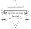
- Fig. 1 is a cross sectional view which shows an entire constitution of the heating apparatus for X-ray inspection according to the present invention.
- the reference number 1 depicts a planar heater; 2, copper plate electrode; 3, screw; 4, crimp-type terminal; 5, covered conductor line; 6, insulating plate high in heat resistance and heat conductivity; 7, print circuit board; 8, electronic component soldered to a semiconductor chip, for example; 9, copper land; 10, solder paste; 13, sealant; 14, shielded heat isolation part; 15, gas supplying pipe; 20, X-ray generating part of X-ray irradiation apparatus; 21, X-ray irradiation range; and 23, X-ray receiving apparatus.
- the planar heater 1 is constituted with, for example, a 30 ⁇ m-thick thin stainless steel plate 1a (for example, SUS430). As shown in Fig. 2 , the planar heater is given an electric resistance value suitable for a heater and provided with a slit 1b for allowing gas to pass.
- the metal plate is extremely low in electric resistance, there is a case where a large current may flow even at a low voltage.
- adoption of a thin-plate formed in a spiral shape makes it possible to easily control electric resistance and a value of electric current.
- a power supply and a cable for general purpose can be used to yield a high heating value.
- the heater 1a made of a metal plate is thin in thickness and therefore unable to keep the plate shape.
- a sandwich structure is provided that, for example, 1 mm-thick insulating plates (for example, those made of boron nitride BN, ceramics and mica) 1c, 1e are used to hold the heater 1a therebetween from both surfaces.
- 1 mm-thick insulating plates for example, those made of boron nitride BN, ceramics and mica
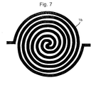
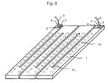
- planar heater 1 there is no particular restriction on the size and shape of the planar heater 1 or the structure, size and shape of the spiral type. Patterns of the spiral type and the zigzag type can be provided in various ways as shown in plan views of Fig. 4 to Fig. 7 . There is no particular restriction on the patterns in addition to those shown in these figures. Where the slit 1b is narrow in width to result in insufficient gas supply, gas holes 1b' may be provided as shown in Fig. 8 .
- the metal plate heater 1a can be formed as a metal-resistant thin film on an insulating plate such as ceramics by vapor deposition of PVD, CVD or others, in addition to etching. It is desirable that a target to which the metal plate heater 1a is deposited is an insulating plate 1e on the side of a sample where oblique gas holes 1f are formed. In this instance, it is also possible to omit an insulating plate 1c on the side of the gaseous space.
- a material of the metal plate is not restricted to an alloy of Fe-Cr such SUS 430 or other stainless steel.
- Other metals which can be formed into a thin film and which are heat resistant, free of deterioration due to oxidation and give resistivity usable as a heater may include alloys of Ni-Cr, Ni-Cr-Fe, Fe-Cr-Al, Cu-Mn, Cn-Ni and other metals.
- Embodiment 1 of the present invention in order to activate the heating apparatus, at first, voltage is applied to a covered conductor line 5.
- the applied voltage may be direct current or alternative current, the current will flow via the crimp-type terminal 4 into the copper plate electrode 2.
- planar heater 1 since the planar heater 1 is firmly attached to the copper plate electrode 2 with the screw 3, the current will flow uniformly inside the planar heater 1.
- the metal plate is low in electric resistance and easily electrified, by which the current flows easily to produce a heating value according to electric power.
- planar heater 1 Since heating is generated uniformly and also the metal plate in itself is high in heat conductivity, the planar heater 1 undergoes rapid and uniform temperature elevation.
- the insulator 6 favorably includes a plate and a sheet made of alumina ceramics, polyimide resin, silicone resin, fluorocarbon resin and mica, with no particular restriction thereon. A material can be selected freely depending on a required temperature. Further, the planar heater 1 may be covered with the insulator 6.
- the sample can be installed directly on the planar heater 1 only via the insulator 6 high in heat resistance and heat conductivity. Therefore, the sample can also be rapidly and uniformly heated in association with a rapid and uniform temperature elevation of the planar heater 1.
- the heating value can be easily controlled by controlling the voltage while being monitored with a thermoelectric couple. It is, thereby, possible to control temperatures of the sample according to a required profile.
- a stainless steel plate of the present embodiment is high in heat resistant temperature and able to sufficiently fuse a solder paste 10.
- the solder paste 10 is melted to wet an electronic component 8 and a copper land 9 and join them.
- the planar heater 1 is formed in a flat plate shape. This plate may be made round or bent, thereby making it possible to provide a cylindrical or rectangular tubular heating apparatus as described in Patent Document 2, for example.
- the present embodiment is characterized in that the metal plate is directly electrified to generate heating.
- a planar heater which is constituted with a carbon-fiber reinforced carbon composite material plate formed of an advanced composite material made of a carbon fiber and a carbon matrix, for example, may be used.
- those which meet the following three characteristics are all included in carbon-fiber reinforced carbon composite materials.
- a first characteristic is that there are no serious disadvantages such as oxidation and deterioration even on heating at 250°C in the atmosphere
- a second characteristic is that electric conductivity is found
- a third characteristic is that carbon fiber is contained at least partially in the material.
- a carbon-fiber reinforced carbon composite material is to have a heat resistant temperature of 250°C or higher.
- the carbon-fiber reinforced carbon composite material is high in heat resistance and can be heated up to a high temperature of 1000°C or higher, if necessary.
- temperature control or gas atmosphere control or forming an oxidation preventing film an observation can be made easily under high temperature conditions.
- various materials and components can be observed for the heating behavior.
- a carbon-fiber reinforced carbon composite material plate can be used as a sealing wall material of the present heating apparatus. Thereby, it is possible to easily obtain a heating apparatus which is light in weight, high in heat resistance, small in size, simple in constitution and high in durability.
- gas which has been supplied through the gas supplying pipe 15 is allowed to pass into the slit 1b provided on the planar heater 1 and heated, by which atmosphere heating due to convection is added to heating due to contact and irradiation, thus making it possible to finely control temperatures elaborately.
- speed of temperature elevation be controlled by the flow rate of the gas but also cycle operation can be conducted between temperature elevation and cooling.
- oxidation and combustion can be prevented or controlled by injecting an inert gas and others, an observation can be made under a specific gas atmosphere, and a poisonous gas generated from a sample can be discharged outside to prevent adverse effects on the sample and an apparatus. Still further, after completion of observation, ambient air or cold air can be sent to cool the sample and the apparatus rapidly.
- Fig. 9 shows Embodiment 2 of the heating apparatus in which the planar heaters 1 shown in Fig. 2 and Fig. 3 are installed above and below.
- the reference number 16 depicts an insulation spacer inserted between the lower planar heater 1 and the print circuit board 7.
- Embodiment 3 of the present invention which is a further improvement of Embodiment 2.
- Fig. 10 is a cross sectional view for explaining Embodiment 3.
- the reference number 22 depicts a window part; 32, heated-air blowing plate; 32a, heated-air blowing hole; 27, sample chamber; and 31, supporting body.
- the gas supplying pipe 15 can be used by being fitted into heated-air blowing holes 14a on the shielded heat isolation part 14 at the heating part shown in the cross sectional view of Fig. 11 .
- the reference number 31a is an exhaust opening formed, for example, on a side surface of the supporting body 31. Since as for the other points, the present embodiment is similar to Embodiment 2, the same reference numbers are used to omit an explanation.
- Embodiment 3 in order to heat a sample, voltage is applied to the planar heater 1, with gas being supplied from the gas supplying pipe 15.
- the voltage may be applied from a part outside the window part 22 at the end of the planar heater 1. Further, the voltage can be applied either by direct current or alternative current.
- a thermoelectric couple can be installed at a part which gives no trouble in making an X-ray observation, thereby monitoring temperatures.
- the heating apparatus is installed horizontally but can be installed vertically or obliquely when necessary.
- Various combination of methods for installing the heating apparatus with methods for setting a sample makes it possible to observe the sample at any angle.
- gas supplied from the gas supplying pipe 15 is elevated in temperature, by which heated-air is blown from the heated-air blowing holes 32a to generate a heated swirling flow inside the sample chamber 27 and elevate the temperature inside the sample chamber 27.
- the print circuit board 7, which is a sample is also elevated in temperature rapidly and uniformly inside the plane, and the solder paste 10 is melted to wet the electronic component 8 and the copper land 9 and join them.
- the heating apparatus of the present invention since only a material excellent in X-ray transmission properties is used at the window part 22 which is an X-ray observation range of a sample, it is possible to observe the wetting behavior of solder clearly under various temperature conditions.
- a real-time observation can be made in a predetermined temperature profile, which is helpful in clarifying a void developing mechanism.
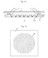
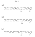
- the heated-air blowing holes 32a are provided minutely in a large number as shown in the plan view of Fig. 12 , thus making it possible to increase the blowing speed of heated-air. Further, the heated-air blowing holes 32a are located so as to be in agreement with a clearance of the planar heater 1 and can be provided freely according to the shape of the planar heater 1, with no particular restriction on the arrangement thereof. Still further, the heated-air blowing holes are provided obliquely, thereby generating a swirling flow without using a mechanism such as a fan to make temperatures uniform more simply. In addition, a way of providing the blowing holes can be set in various directions as shown in the cross sectional views of Fig. 13 (a), (b) and (c) . There is no particular restriction on the directions, in addition to those shown in the figure.
- gas supplying pipes 15 may be provided, thereby making it possible to eliminate an unevenness in gas flow and also attain a uniform temperature.
- the flow rate of gas can also be referred to control the speed of temperature elevation.
- gas supplied from the gas supplying pipe 15 may by selected, by which it is possible to make an observation under a specific gas atmosphere and also prevent or control oxidation and combustion by injecting an inert gas or others.
- the gas supplying pipe 15 may be constituted with a material excellent in X-ray transmission properties, by which the supply of gas can be controlled, with the X-ray transmission properties kept.
- a coolant gas is allowed to flow through the gas supplying pipe 15.
- a gas supplying pipe exclusively for cooling is provided on the supporting bodies 31, thus making it possible to control cooling rapidly. Thereby, it becomes possible to control rapid cooling and a state of cooling, by which it is possible to observe cooling effects on various phenomena such as a liftoff phenomenon and also conduct a cycle operation between temperature elevation and cooling.
- an exhaust opening 31a may be provided on the supporting body 31 of the heating apparatus, thus making it possible to control the gas atmosphere and flow rate and also control temperatures easily. Further, it is possible to provide a heating apparatus capable of discharging quickly a poisonous gas generated from a sample on heating and high in safety.
- the planar heater 1 constituted with a material excellent in X-ray transmission properties is used.
- the planar heater 1 is made of carbon in particular, thereby providing a heater capable of transmitting X-rays and also easily attaining uniform temperature elevation by electrification.
- carbon fibers may be formed into a plane shape and used.
- electricity will flow easily to generate a heating value according to electric power due to the small electric resistance and easy electrification. This heating is uniform and a carbon-fiber reinforced carbon composite material plate itself is also high in heat conductivity, thus making it possible to elevate the temperature of the planar heater 1 rapidly and uniformly.
- an oxidation preventing film may be provided on the surface of carbon, thus making it possible to prevent the oxidation and deterioration of carbon and also improve the durability.
- Materials of the oxidation preventing film include oxidation preventing films made of titanium diboride and silicon carbide, with no restriction thereon.
- the present embodiment is characterized in that a material of the shielded heat isolation part 14 and that of the heated-air blowing plate 32 are any one of ceramics, heat resistant resin, heat resistant rubber, glass, glass fiber, mica and insulation-treated carbon or a combination thereof. These materials are favorable in X-ray transmission properties and also excellent in durability, heat resistance and insulating properties and, therefore, used favorably. More specifically, a plate and a sheet made of alumina ceramics, polyimide resin, silicone resin, fluorocarbon resin, glass, glass fiber, mica or insulation-treated carbon are favorably used. In addition to these materials, the materials can be selected freely depending on a required temperature and strength, with no particular restriction thereon. Further, carbon can be subjected to insulation treatment by various methods such as coating with an insulating material and doping into an insulating agent, with no particular restriction thereon.
- the present embodiment is also characterized in that a material of the gas supplying pipe 15 and that of a jig for fixing the shielded heat isolation part 14, the gas supplying pipe 15 or the heated-air blowing plate 32 are any one of ceramics, heat-resistant resin, heat-resistant rubber or a combination thereof. These materials are favorable in X-ray transmission properties and also excellent in durability, heat resistance and insulating properties and, therefore, can be used favorably. More specifically, in addition to these materials, alumina ceramics, polyimide resin, silicone resin and fluorocarbon resin are favorably used, with no particular restriction thereon. The materials can be selected freely depending on a required temperature and strength.
- the present embodiment is characterized in that it is constituted on rigid supporting bodies 31 which oppose each other, the shielded heat isolation part 14, the planar heater 1 and the heated-air blowing plate 32 are arranged at one of the window part 22 and, of the shielded heat isolation part 14, the planar heater 1 and the heated-air blowing plate 32, at least the shielded heat isolation part 14 is arranged at the other of the window part 22.
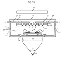
- a sample can be heated by selecting a heating method depending on types of the sample, for example, convection heating from both surfaces of the sample as shown in the cross sectional view of Fig.
- the supporting bodies 31 can be joined by using a hinge as shown in the perspective view of Fig. 16 so as to be opened and closed.
- the supporting bodies 31 are allowed to be fitted into or to slide, with no particular restriction on the mechanism.
- a limit switch 40 may be installed between the supporting bodies 31, thus making it possible to conduct heating only when the supporting bodies 31 are closed. Therefore, it is possible to prevent an accident.
- the limit switch 40 since the side of a lid is slightly widened laterally from the side of the main body to install the limit switch 40 outside, the limit switch 40 is less likely to be influenced by high temperatures inside and also the lid can be closed securely.
- a pressure sensor 42 may be disposed on the gas supplying pipe 15, thus making it possible to conduct heating only when gas is supplied. Thus, it is possible to prevent an accident such as overheating of the heating apparatus.
- the limit switch 40 and the pressure sensor 42 are required to be provided outside the range of the window part 22.
- the planar heater 1, the shielded heat isolation part 14 and the heated-air blowing plate 32 are repeatedly subjected to heat cycle and therefore expected to be deteriorated earlier than other components.
- the planar heater 1 may be deteriorated due to oxidation at a high temperature.
- the planar heater 1, the shielded heat isolation part 14, and the heated-air blowing plate 32 provided when necessary may be made available as modules, thereby only worn parts can be exchanged to improve the maintenance and cost performance.
- the heating apparatus of the present invention is characterized as being a reflow furnace. Thereby, it is possible to provide a reflow furnace capable of examining a board with an X-ray and easily controlling temperatures.
- Planar heaters made of a carbon-fiber reinforced carbon composite material plate were disposed above and below and formed into the shape shown in Fig. 1 . Then, they were used to fabricate a heating apparatus.
- Planar heaters made of a carbon-fiber reinforced carbon composite material plate were disposed above and below and formed into the shape shown in Fig. 9 . Then, they were used to fabricate a heating apparatus.
- Planar heaters made of a carbon-fiber reinforced carbon composite material plate and ceramics plates were used to fabricate the heating apparatus shown in Fig. 10 and Fig. 16 .
- Planar heaters made of a carbon-fiber reinforced carbon composite material plate and ceramics plates were used to fabricate the heating apparatus shown in Fig. 14 and Fig. 16 .
- a planar heater made of a carbon-fiber reinforced carbon composite material plate and a ceramics plate were used to fabricate the heating apparatus shown in Fig. 15 and Fig. 16 .
- Heaters made of carbon fiber and processed into a plane shape and ceramics plates were used to fabricate the heating apparatus shown in Fig. 10 and Fig. 16 .
- a ceramics heater was used to fabricate a heating apparatus.
- a sheathed heater having a nichrome wire as a heating source and a blower fan were used to fabricate a heating apparatus.
- any one of the heating apparatuses shown in Embodiments 1 to 6 underwent rapid and uniform temperature elevation according to a predetermined profile. Further, an X-ray observation was able to be made in real time for a motion image in which solder in a melted state vibrated under a ceramics condenser component and jumped out immediately before solidification.
- the heating apparatus of Comparative example 1 was slow in temperature elevation and unable to effect temperature elevation according to a predetermined profile.
- the heating apparatus of Comparative example 2 was also slow in temperature elevation, unable to effect temperature elevation according to a predetermined profile and also unable to heat a sample to a required temperature.
- the heating apparatus for X-ray inspection is useful in analyzing a cause of defective generation at a solder joint part in particular and able to heat an object to be examined such as a sample to a target temperature or heat it according to a predetermined profile, thereby observing and recording the change in the state in real time.
Landscapes
- Chemical & Material Sciences (AREA)
- Engineering & Computer Science (AREA)
- Ceramic Engineering (AREA)
- Inorganic Chemistry (AREA)
- Analysing Materials By The Use Of Radiation (AREA)
Applications Claiming Priority (3)
| Application Number | Priority Date | Filing Date | Title |
|---|---|---|---|
| JP2009092593A JP5290030B2 (ja) | 2009-04-07 | 2009-04-07 | エックス線検査用加熱装置 |
| JP2009270718 | 2009-11-09 | ||
| PCT/JP2010/052932 WO2010116809A1 (fr) | 2009-04-07 | 2010-02-25 | Appareil de chauffage pour inspection par rayons x |
Publications (3)
| Publication Number | Publication Date |
|---|---|
| EP2293050A1 true EP2293050A1 (fr) | 2011-03-09 |
| EP2293050A4 EP2293050A4 (fr) | 2012-11-21 |
| EP2293050B1 EP2293050B1 (fr) | 2016-09-07 |
Family
ID=42936097
Family Applications (1)
| Application Number | Title | Priority Date | Filing Date |
|---|---|---|---|
| EP10761511.4A Not-in-force EP2293050B1 (fr) | 2009-04-07 | 2010-02-25 | Appareil de chauffage pour inspection par rayons x |
Country Status (3)
| Country | Link |
|---|---|
| US (2) | US9161392B2 (fr) |
| EP (1) | EP2293050B1 (fr) |
| WO (1) | WO2010116809A1 (fr) |
Cited By (5)
| Publication number | Priority date | Publication date | Assignee | Title |
|---|---|---|---|---|
| CN104569010A (zh) * | 2015-02-10 | 2015-04-29 | 中国科学院上海应用物理研究所 | 一种用于同步辐射x射线衍射测试的联动装置 |
| CN110927188A (zh) * | 2019-12-17 | 2020-03-27 | 西南交通大学 | 一种用于轻气炮加载实验的加温靶装置及其使用方法 |
| US10841980B2 (en) | 2015-10-19 | 2020-11-17 | Laminaheat Holding Ltd. | Laminar heating elements with customized or non-uniform resistance and/or irregular shapes and processes for manufacture |
| US10925119B2 (en) | 2015-01-12 | 2021-02-16 | Laminaheat Holding Ltd. | Fabric heating element |
| USD911038S1 (en) | 2019-10-11 | 2021-02-23 | Laminaheat Holding Ltd. | Heating element sheet having perforations |
Families Citing this family (6)
| Publication number | Priority date | Publication date | Assignee | Title |
|---|---|---|---|---|
| US9161392B2 (en) * | 2009-04-07 | 2015-10-13 | Yoshinobu ANBE | Heating apparatus for X-ray inspection |
| JP5812609B2 (ja) * | 2011-01-13 | 2015-11-17 | 株式会社東光高岳 | 加熱装置 |
| CN105051898B (zh) * | 2013-08-23 | 2018-01-16 | 富士电机株式会社 | 半导体装置 |
| JP6459406B2 (ja) * | 2014-11-04 | 2019-01-30 | 住友電気工業株式会社 | 炭化珪素単結晶の製造装置および炭化珪素単結晶の製造方法 |
| JP6868163B2 (ja) * | 2017-04-04 | 2021-05-12 | 進 中谷 | 検査用熱処理炉を備えた検査装置 |
| WO2022211875A1 (fr) * | 2021-03-29 | 2022-10-06 | Micropyretics Heaters International, Inc. | Élément chauffant configuré en double spirale inversée efficace en énergie et dispositif de chauffage à gaz l'utilisant |
Family Cites Families (48)
| Publication number | Priority date | Publication date | Assignee | Title |
|---|---|---|---|---|
| GB1128107A (en) * | 1965-06-23 | 1968-09-25 | Hitachi Ltd | Scanning electron microscope |
| US3374349A (en) * | 1966-11-14 | 1968-03-19 | Victor G. Macres | Electron probe having a specific shortfocal length magnetic lens and light microscope |
| US3495328A (en) * | 1967-07-07 | 1970-02-17 | Corning Glass Works | Electric heating unit |
| JPS491058B1 (fr) * | 1969-09-24 | 1974-01-11 | ||
| US4367388A (en) * | 1979-06-06 | 1983-01-04 | Hitachi Heating Appliances Co., Ltd. | Cooking heating apparatus |
| JPS5669889A (en) | 1979-11-12 | 1981-06-11 | Fujitsu Ltd | Method of plating printed circuit board |
| JPS57128482A (en) | 1981-01-31 | 1982-08-10 | Matsushita Electric Works Ltd | Heat sensitive panel heater |
| US4501144A (en) * | 1982-09-30 | 1985-02-26 | Honeywell Inc. | Flow sensor |
| JPS6311756A (ja) | 1986-06-30 | 1988-01-19 | 株式会社ナカ技術研究所 | 支柱固定用アンカ− |
| US4827761A (en) * | 1987-06-25 | 1989-05-09 | Shell Oil Company | Sample holder |
| JPH0455792A (ja) | 1990-06-26 | 1992-02-24 | Seiko Epson Corp | 時刻表示装置 |
| JP2961440B2 (ja) | 1990-10-22 | 1999-10-12 | 東芝セラミックス株式会社 | カーボンヒータ |
| DE69229432T2 (de) * | 1991-10-24 | 2000-02-17 | Hitachi, Ltd. | Probenhalter für Elektronenmikroskop |
| US5396574A (en) * | 1992-03-26 | 1995-03-07 | Process Technology, Inc. | Tubular high efficiency, non-contaminating fluid heater |
| TW293983B (fr) * | 1993-12-17 | 1996-12-21 | Tokyo Electron Co Ltd | |
| JPH07307377A (ja) * | 1993-12-27 | 1995-11-21 | Shin Etsu Chem Co Ltd | 静電チャック付セラミックスヒーター |
| JPH07286945A (ja) | 1994-04-15 | 1995-10-31 | Nippon Steel Corp | X線測定用試料加熱炉 |
| JPH07296955A (ja) | 1994-04-22 | 1995-11-10 | Nippon Steel Corp | カーボンヒーター |
| US6337479B1 (en) * | 1994-07-28 | 2002-01-08 | Victor B. Kley | Object inspection and/or modification system and method |
| NZ272635A (en) * | 1994-08-02 | 1998-02-26 | Mcneil Ppc Inc | Laser cutting/drilling processing head that creates a vortex gas flow within the head to clean and prevent back spatting of particles onto the lens therein |
| JPH0997783A (ja) * | 1995-09-28 | 1997-04-08 | Nec Corp | プラズマ処理装置 |
| US5922223A (en) * | 1995-11-16 | 1999-07-13 | Matsushita Electric Industrial Co., Ltd. | Plasma processing method and apparatus |
| JP2820089B2 (ja) | 1995-11-17 | 1998-11-05 | 日本電気株式会社 | 均熱加熱装置 |
| US5811755A (en) * | 1996-01-11 | 1998-09-22 | Lockheed Martin Corp. | Weld repair method for aluminum lithium seam |
| US5689542A (en) * | 1996-06-06 | 1997-11-18 | Varian Associates, Inc. | X-ray generating apparatus with a heat transfer device |
| US5698856A (en) * | 1996-08-05 | 1997-12-16 | Frasca; Peter | Specimen holder for electron microscope |
| JPH10208855A (ja) | 1997-01-23 | 1998-08-07 | Toshiba Ceramics Co Ltd | 面状ヒータ |
| JP3867393B2 (ja) * | 1998-03-20 | 2007-01-10 | 株式会社デンソー | マイクロヒータおよびその製造方法ならびにエアフローセンサ |
| JP2001007506A (ja) | 1999-06-22 | 2001-01-12 | Nippon Antomu Kogyo Kk | リフローハンダ付け方法およびその装置 |
| JP4602536B2 (ja) | 2000-11-27 | 2010-12-22 | 株式会社タムラ製作所 | リフローはんだ付け装置 |
| US6960743B2 (en) * | 2000-12-05 | 2005-11-01 | Ibiden Co., Ltd. | Ceramic substrate for semiconductor manufacturing, and method of manufacturing the ceramic substrate |
| US20050124036A1 (en) * | 2002-02-06 | 2005-06-09 | Rudy Susilo | Method for producing recombinant proteins in micro-organisms |
| WO2003107721A1 (fr) * | 2002-06-01 | 2003-12-24 | Http-Hypothermia Therapy Ltd. | Dispositif de chauffage electrique, destine en particulier a chauffer l'anatomie d'un patient |
| US6914220B2 (en) * | 2002-09-24 | 2005-07-05 | The Regents Of The University Of Michigan | Microelectromechanical heating apparatus and fluid preconcentrator device utilizing same |
| JP2004125582A (ja) * | 2002-10-02 | 2004-04-22 | Rigaku Corp | 分析装置及び分析方法 |
| JP2005166269A (ja) * | 2003-11-28 | 2005-06-23 | Showa Mfg Co Ltd | 面状ヒータ、及び同面状ヒータの発熱量調整方法 |
| KR100750586B1 (ko) * | 2003-12-26 | 2007-08-20 | 한국전자통신연구원 | 미소유체 가열 시스템 |
| JP2005227188A (ja) | 2004-02-13 | 2005-08-25 | Cores:Kk | 観察装置 |
| JP2005353712A (ja) | 2004-06-09 | 2005-12-22 | Okuhara Electric Inc | X線透視カメラを含む半田付装置 |
| NL1027025C2 (nl) * | 2004-09-13 | 2006-03-14 | Univ Delft Tech | Microreactor voor een transmissie elektronenmicroscoop en verwarmingselement en werkwijze voor vervaardiging daarvan. |
| TWI281833B (en) * | 2004-10-28 | 2007-05-21 | Kyocera Corp | Heater, wafer heating apparatus and method for manufacturing heater |
| JP2006165402A (ja) * | 2004-12-09 | 2006-06-22 | Toyota Motor Corp | はんだ付け装置とはんだ付け方法 |
| US7589323B2 (en) * | 2005-01-24 | 2009-09-15 | Sii Nanotechnology Inc. | Superconducting X-ray detector and X-ray analysis apparatus using the same |
| JP2006251563A (ja) * | 2005-03-11 | 2006-09-21 | Seikoh Giken Co Ltd | 導波路型可変光減衰器 |
| JP5224726B2 (ja) * | 2006-07-10 | 2013-07-03 | キヤノン株式会社 | 放射線画像撮影装置及びその制御方法 |
| CN201114811Y (zh) * | 2007-08-06 | 2008-09-10 | 熊猫电子集团有限公司 | 加热板 |
| JP2009123796A (ja) | 2007-11-13 | 2009-06-04 | Cores:Kk | リフロー加熱装置 |
| US9161392B2 (en) * | 2009-04-07 | 2015-10-13 | Yoshinobu ANBE | Heating apparatus for X-ray inspection |
-
2010
- 2010-02-25 US US12/737,851 patent/US9161392B2/en not_active Expired - Fee Related
- 2010-02-25 EP EP10761511.4A patent/EP2293050B1/fr not_active Not-in-force
- 2010-02-25 WO PCT/JP2010/052932 patent/WO2010116809A1/fr not_active Ceased
- 2010-12-30 US US12/982,568 patent/US20110096902A1/en not_active Abandoned
Cited By (5)
| Publication number | Priority date | Publication date | Assignee | Title |
|---|---|---|---|---|
| US10925119B2 (en) | 2015-01-12 | 2021-02-16 | Laminaheat Holding Ltd. | Fabric heating element |
| CN104569010A (zh) * | 2015-02-10 | 2015-04-29 | 中国科学院上海应用物理研究所 | 一种用于同步辐射x射线衍射测试的联动装置 |
| US10841980B2 (en) | 2015-10-19 | 2020-11-17 | Laminaheat Holding Ltd. | Laminar heating elements with customized or non-uniform resistance and/or irregular shapes and processes for manufacture |
| USD911038S1 (en) | 2019-10-11 | 2021-02-23 | Laminaheat Holding Ltd. | Heating element sheet having perforations |
| CN110927188A (zh) * | 2019-12-17 | 2020-03-27 | 西南交通大学 | 一种用于轻气炮加载实验的加温靶装置及其使用方法 |
Also Published As
| Publication number | Publication date |
|---|---|
| EP2293050B1 (fr) | 2016-09-07 |
| WO2010116809A1 (fr) | 2010-10-14 |
| US9161392B2 (en) | 2015-10-13 |
| US20110147364A1 (en) | 2011-06-23 |
| EP2293050A4 (fr) | 2012-11-21 |
| US20110096902A1 (en) | 2011-04-28 |
Similar Documents
| Publication | Publication Date | Title |
|---|---|---|
| EP2293050B1 (fr) | Appareil de chauffage pour inspection par rayons x | |
| US20060275933A1 (en) | Thermally conductive ceramic tipped contact thermocouple | |
| JP5633071B2 (ja) | 熱放射光源を用いた放射温度計の校正方法 | |
| JP2013512171A (ja) | 制御された厚さを有するガラスシートを製造する方法および装置 | |
| Lee et al. | Design and construction of a compact vacuum furnace for scientific research | |
| JP2022505501A (ja) | 加熱手段を内蔵した固体酸化物電気化学システム | |
| US20080041836A1 (en) | High temperature heating element for preventing contamination of a work piece | |
| CN102803928B (zh) | 可加热的流通测量皿 | |
| CN105642206A (zh) | 一种铍水反应装置 | |
| KR101258826B1 (ko) | 열전소자를 이용한 콜드트랩 | |
| JP4959844B2 (ja) | X線検査用加熱装置 | |
| JP5290030B2 (ja) | エックス線検査用加熱装置 | |
| CN102017789A (zh) | 发热体单元及加热装置 | |
| JP5818106B2 (ja) | X線検査用加熱装置及び面状ヒーター | |
| CN108886086A (zh) | 热电模块发电评价装置 | |
| US20120120986A1 (en) | Thermocouple and thermometer using that | |
| RU32953U1 (ru) | Электронагреватель | |
| JP3828815B2 (ja) | 加熱炉の温度制御装置 | |
| JP2003227764A (ja) | 加熱炉 | |
| JP5384814B2 (ja) | ヒータユニット及びx線解析装置 | |
| CN116601121A (zh) | 玻璃熔融炉监视方法及玻璃物品制造方法 | |
| US20040134480A1 (en) | Convective system | |
| Sapritsky et al. | High-temperature blackbody sources for precision radiometry | |
| Anhalt et al. | Large-and Small-Aperture Fixed-Point Cells of Cu, Pt–C, and Re–C | |
| JP4521083B2 (ja) | ヒータ用電極及び半導体製造装置 |
Legal Events
| Date | Code | Title | Description |
|---|---|---|---|
| PUAI | Public reference made under article 153(3) epc to a published international application that has entered the european phase |
Free format text: ORIGINAL CODE: 0009012 |
|
| AK | Designated contracting states |
Kind code of ref document: A1 Designated state(s): AT BE BG CH CY CZ DE DK EE ES FI FR GB GR HR HU IE IS IT LI LT LU LV MC MK MT NL NO PL PT RO SE SI SK SM TR |
|
| AX | Request for extension of the european patent |
Extension state: AL BA RS |
|
| 17P | Request for examination filed |
Effective date: 20110930 |
|
| RBV | Designated contracting states (corrected) |
Designated state(s): AT BE BG CH CY CZ DE DK EE ES FI FR GB GR HR HU IE IS IT LI LT LU LV MC MK MT NL NO PL PT RO SE SI SK SM TR |
|
| DAX | Request for extension of the european patent (deleted) | ||
| A4 | Supplementary search report drawn up and despatched |
Effective date: 20121024 |
|
| RIC1 | Information provided on ipc code assigned before grant |
Ipc: H05B 3/14 20060101ALI20121019BHEP Ipc: G01N 23/04 20060101AFI20121019BHEP |
|
| 17Q | First examination report despatched |
Effective date: 20150710 |
|
| GRAP | Despatch of communication of intention to grant a patent |
Free format text: ORIGINAL CODE: EPIDOSNIGR1 |
|
| INTG | Intention to grant announced |
Effective date: 20160329 |
|
| GRAS | Grant fee paid |
Free format text: ORIGINAL CODE: EPIDOSNIGR3 |
|
| GRAA | (expected) grant |
Free format text: ORIGINAL CODE: 0009210 |
|
| RAP1 | Party data changed (applicant data changed or rights of an application transferred) |
Owner name: ANBE SMT CO. |
|
| RIN1 | Information on inventor provided before grant (corrected) |
Inventor name: ANBE, YOSHINOBU |
|
| AK | Designated contracting states |
Kind code of ref document: B1 Designated state(s): AT BE BG CH CY CZ DE DK EE ES FI FR GB GR HR HU IE IS IT LI LT LU LV MC MK MT NL NO PL PT RO SE SI SK SM TR |
|
| REG | Reference to a national code |
Ref country code: GB Ref legal event code: FG4D |
|
| REG | Reference to a national code |
Ref country code: CH Ref legal event code: EP |
|
| REG | Reference to a national code |
Ref country code: IE Ref legal event code: FG4D |
|
| REG | Reference to a national code |
Ref country code: AT Ref legal event code: REF Ref document number: 827310 Country of ref document: AT Kind code of ref document: T Effective date: 20161015 |
|
| REG | Reference to a national code |
Ref country code: DE Ref legal event code: R096 Ref document number: 602010036238 Country of ref document: DE |
|
| REG | Reference to a national code |
Ref country code: CH Ref legal event code: NV Representative=s name: BOVARD AG, CH |
|
| REG | Reference to a national code |
Ref country code: LT Ref legal event code: MG4D |
|
| REG | Reference to a national code |
Ref country code: NL Ref legal event code: MP Effective date: 20160907 |
|
| PG25 | Lapsed in a contracting state [announced via postgrant information from national office to epo] |
Ref country code: HR Free format text: LAPSE BECAUSE OF FAILURE TO SUBMIT A TRANSLATION OF THE DESCRIPTION OR TO PAY THE FEE WITHIN THE PRESCRIBED TIME-LIMIT Effective date: 20160907 Ref country code: NO Free format text: LAPSE BECAUSE OF FAILURE TO SUBMIT A TRANSLATION OF THE DESCRIPTION OR TO PAY THE FEE WITHIN THE PRESCRIBED TIME-LIMIT Effective date: 20161207 Ref country code: LT Free format text: LAPSE BECAUSE OF FAILURE TO SUBMIT A TRANSLATION OF THE DESCRIPTION OR TO PAY THE FEE WITHIN THE PRESCRIBED TIME-LIMIT Effective date: 20160907 Ref country code: FI Free format text: LAPSE BECAUSE OF FAILURE TO SUBMIT A TRANSLATION OF THE DESCRIPTION OR TO PAY THE FEE WITHIN THE PRESCRIBED TIME-LIMIT Effective date: 20160907 |
|
| REG | Reference to a national code |
Ref country code: AT Ref legal event code: MK05 Ref document number: 827310 Country of ref document: AT Kind code of ref document: T Effective date: 20160907 |
|
| REG | Reference to a national code |
Ref country code: FR Ref legal event code: PLFP Year of fee payment: 8 |
|
| PG25 | Lapsed in a contracting state [announced via postgrant information from national office to epo] |
Ref country code: GR Free format text: LAPSE BECAUSE OF FAILURE TO SUBMIT A TRANSLATION OF THE DESCRIPTION OR TO PAY THE FEE WITHIN THE PRESCRIBED TIME-LIMIT Effective date: 20161208 Ref country code: SE Free format text: LAPSE BECAUSE OF FAILURE TO SUBMIT A TRANSLATION OF THE DESCRIPTION OR TO PAY THE FEE WITHIN THE PRESCRIBED TIME-LIMIT Effective date: 20160907 Ref country code: LV Free format text: LAPSE BECAUSE OF FAILURE TO SUBMIT A TRANSLATION OF THE DESCRIPTION OR TO PAY THE FEE WITHIN THE PRESCRIBED TIME-LIMIT Effective date: 20160907 Ref country code: ES Free format text: LAPSE BECAUSE OF FAILURE TO SUBMIT A TRANSLATION OF THE DESCRIPTION OR TO PAY THE FEE WITHIN THE PRESCRIBED TIME-LIMIT Effective date: 20160907 Ref country code: NL Free format text: LAPSE BECAUSE OF FAILURE TO SUBMIT A TRANSLATION OF THE DESCRIPTION OR TO PAY THE FEE WITHIN THE PRESCRIBED TIME-LIMIT Effective date: 20160907 |
|
| PG25 | Lapsed in a contracting state [announced via postgrant information from national office to epo] |
Ref country code: RO Free format text: LAPSE BECAUSE OF FAILURE TO SUBMIT A TRANSLATION OF THE DESCRIPTION OR TO PAY THE FEE WITHIN THE PRESCRIBED TIME-LIMIT Effective date: 20160907 Ref country code: EE Free format text: LAPSE BECAUSE OF FAILURE TO SUBMIT A TRANSLATION OF THE DESCRIPTION OR TO PAY THE FEE WITHIN THE PRESCRIBED TIME-LIMIT Effective date: 20160907 |
|
| PG25 | Lapsed in a contracting state [announced via postgrant information from national office to epo] |
Ref country code: IS Free format text: LAPSE BECAUSE OF FAILURE TO SUBMIT A TRANSLATION OF THE DESCRIPTION OR TO PAY THE FEE WITHIN THE PRESCRIBED TIME-LIMIT Effective date: 20170107 Ref country code: PL Free format text: LAPSE BECAUSE OF FAILURE TO SUBMIT A TRANSLATION OF THE DESCRIPTION OR TO PAY THE FEE WITHIN THE PRESCRIBED TIME-LIMIT Effective date: 20160907 Ref country code: SM Free format text: LAPSE BECAUSE OF FAILURE TO SUBMIT A TRANSLATION OF THE DESCRIPTION OR TO PAY THE FEE WITHIN THE PRESCRIBED TIME-LIMIT Effective date: 20160907 Ref country code: AT Free format text: LAPSE BECAUSE OF FAILURE TO SUBMIT A TRANSLATION OF THE DESCRIPTION OR TO PAY THE FEE WITHIN THE PRESCRIBED TIME-LIMIT Effective date: 20160907 Ref country code: CZ Free format text: LAPSE BECAUSE OF FAILURE TO SUBMIT A TRANSLATION OF THE DESCRIPTION OR TO PAY THE FEE WITHIN THE PRESCRIBED TIME-LIMIT Effective date: 20160907 Ref country code: SK Free format text: LAPSE BECAUSE OF FAILURE TO SUBMIT A TRANSLATION OF THE DESCRIPTION OR TO PAY THE FEE WITHIN THE PRESCRIBED TIME-LIMIT Effective date: 20160907 Ref country code: BE Free format text: LAPSE BECAUSE OF FAILURE TO SUBMIT A TRANSLATION OF THE DESCRIPTION OR TO PAY THE FEE WITHIN THE PRESCRIBED TIME-LIMIT Effective date: 20160907 Ref country code: PT Free format text: LAPSE BECAUSE OF FAILURE TO SUBMIT A TRANSLATION OF THE DESCRIPTION OR TO PAY THE FEE WITHIN THE PRESCRIBED TIME-LIMIT Effective date: 20170109 Ref country code: BG Free format text: LAPSE BECAUSE OF FAILURE TO SUBMIT A TRANSLATION OF THE DESCRIPTION OR TO PAY THE FEE WITHIN THE PRESCRIBED TIME-LIMIT Effective date: 20161207 |
|
| REG | Reference to a national code |
Ref country code: DE Ref legal event code: R097 Ref document number: 602010036238 Country of ref document: DE |
|
| PG25 | Lapsed in a contracting state [announced via postgrant information from national office to epo] |
Ref country code: IT Free format text: LAPSE BECAUSE OF FAILURE TO SUBMIT A TRANSLATION OF THE DESCRIPTION OR TO PAY THE FEE WITHIN THE PRESCRIBED TIME-LIMIT Effective date: 20160907 |
|
| PLBE | No opposition filed within time limit |
Free format text: ORIGINAL CODE: 0009261 |
|
| STAA | Information on the status of an ep patent application or granted ep patent |
Free format text: STATUS: NO OPPOSITION FILED WITHIN TIME LIMIT |
|
| PG25 | Lapsed in a contracting state [announced via postgrant information from national office to epo] |
Ref country code: DK Free format text: LAPSE BECAUSE OF FAILURE TO SUBMIT A TRANSLATION OF THE DESCRIPTION OR TO PAY THE FEE WITHIN THE PRESCRIBED TIME-LIMIT Effective date: 20160907 |
|
| 26N | No opposition filed |
Effective date: 20170608 |
|
| PG25 | Lapsed in a contracting state [announced via postgrant information from national office to epo] |
Ref country code: SI Free format text: LAPSE BECAUSE OF FAILURE TO SUBMIT A TRANSLATION OF THE DESCRIPTION OR TO PAY THE FEE WITHIN THE PRESCRIBED TIME-LIMIT Effective date: 20160907 |
|
| PG25 | Lapsed in a contracting state [announced via postgrant information from national office to epo] |
Ref country code: MC Free format text: LAPSE BECAUSE OF FAILURE TO SUBMIT A TRANSLATION OF THE DESCRIPTION OR TO PAY THE FEE WITHIN THE PRESCRIBED TIME-LIMIT Effective date: 20160907 |
|
| REG | Reference to a national code |
Ref country code: IE Ref legal event code: MM4A |
|
| PG25 | Lapsed in a contracting state [announced via postgrant information from national office to epo] |
Ref country code: LU Free format text: LAPSE BECAUSE OF NON-PAYMENT OF DUE FEES Effective date: 20170225 |
|
| REG | Reference to a national code |
Ref country code: FR Ref legal event code: PLFP Year of fee payment: 9 |
|
| PG25 | Lapsed in a contracting state [announced via postgrant information from national office to epo] |
Ref country code: IE Free format text: LAPSE BECAUSE OF NON-PAYMENT OF DUE FEES Effective date: 20170225 |
|
| PG25 | Lapsed in a contracting state [announced via postgrant information from national office to epo] |
Ref country code: MT Free format text: LAPSE BECAUSE OF NON-PAYMENT OF DUE FEES Effective date: 20170225 |
|
| PGFP | Annual fee paid to national office [announced via postgrant information from national office to epo] |
Ref country code: CH Payment date: 20190221 Year of fee payment: 10 Ref country code: GB Payment date: 20190221 Year of fee payment: 10 Ref country code: DE Payment date: 20190111 Year of fee payment: 10 |
|
| PGFP | Annual fee paid to national office [announced via postgrant information from national office to epo] |
Ref country code: FR Payment date: 20190221 Year of fee payment: 10 |
|
| PG25 | Lapsed in a contracting state [announced via postgrant information from national office to epo] |
Ref country code: HU Free format text: LAPSE BECAUSE OF FAILURE TO SUBMIT A TRANSLATION OF THE DESCRIPTION OR TO PAY THE FEE WITHIN THE PRESCRIBED TIME-LIMIT; INVALID AB INITIO Effective date: 20100225 |
|
| PG25 | Lapsed in a contracting state [announced via postgrant information from national office to epo] |
Ref country code: CY Free format text: LAPSE BECAUSE OF NON-PAYMENT OF DUE FEES Effective date: 20160907 |
|
| PG25 | Lapsed in a contracting state [announced via postgrant information from national office to epo] |
Ref country code: MK Free format text: LAPSE BECAUSE OF FAILURE TO SUBMIT A TRANSLATION OF THE DESCRIPTION OR TO PAY THE FEE WITHIN THE PRESCRIBED TIME-LIMIT Effective date: 20160907 |
|
| PG25 | Lapsed in a contracting state [announced via postgrant information from national office to epo] |
Ref country code: TR Free format text: LAPSE BECAUSE OF FAILURE TO SUBMIT A TRANSLATION OF THE DESCRIPTION OR TO PAY THE FEE WITHIN THE PRESCRIBED TIME-LIMIT Effective date: 20160907 |
|
| REG | Reference to a national code |
Ref country code: DE Ref legal event code: R119 Ref document number: 602010036238 Country of ref document: DE |
|
| REG | Reference to a national code |
Ref country code: CH Ref legal event code: PL |
|
| GBPC | Gb: european patent ceased through non-payment of renewal fee |
Effective date: 20200225 |
|
| PG25 | Lapsed in a contracting state [announced via postgrant information from national office to epo] |
Ref country code: LI Free format text: LAPSE BECAUSE OF NON-PAYMENT OF DUE FEES Effective date: 20200229 Ref country code: CH Free format text: LAPSE BECAUSE OF NON-PAYMENT OF DUE FEES Effective date: 20200229 |
|
| PG25 | Lapsed in a contracting state [announced via postgrant information from national office to epo] |
Ref country code: GB Free format text: LAPSE BECAUSE OF NON-PAYMENT OF DUE FEES Effective date: 20200225 Ref country code: DE Free format text: LAPSE BECAUSE OF NON-PAYMENT OF DUE FEES Effective date: 20200901 Ref country code: FR Free format text: LAPSE BECAUSE OF NON-PAYMENT OF DUE FEES Effective date: 20200229 |