EP2293060A2 - Gassensor - Google Patents
Gassensor Download PDFInfo
- Publication number
- EP2293060A2 EP2293060A2 EP10174742A EP10174742A EP2293060A2 EP 2293060 A2 EP2293060 A2 EP 2293060A2 EP 10174742 A EP10174742 A EP 10174742A EP 10174742 A EP10174742 A EP 10174742A EP 2293060 A2 EP2293060 A2 EP 2293060A2
- Authority
- EP
- European Patent Office
- Prior art keywords
- gas
- sensor element
- gas sensor
- ozone
- sample gas
- Prior art date
- Legal status (The legal status is an assumption and is not a legal conclusion. Google has not performed a legal analysis and makes no representation as to the accuracy of the status listed.)
- Withdrawn
Links
- 239000003054 catalyst Substances 0.000 claims abstract description 81
- BQCADISMDOOEFD-UHFFFAOYSA-N Silver Chemical compound [Ag] BQCADISMDOOEFD-UHFFFAOYSA-N 0.000 claims abstract description 64
- 229910052709 silver Inorganic materials 0.000 claims abstract description 64
- 239000004332 silver Substances 0.000 claims abstract description 64
- 239000004065 semiconductor Substances 0.000 claims abstract description 50
- 238000011144 upstream manufacturing Methods 0.000 claims description 8
- QGLKJKCYBOYXKC-UHFFFAOYSA-N nonaoxidotritungsten Chemical compound O=[W]1(=O)O[W](=O)(=O)O[W](=O)(=O)O1 QGLKJKCYBOYXKC-UHFFFAOYSA-N 0.000 claims 1
- 229910001930 tungsten oxide Inorganic materials 0.000 claims 1
- 230000035945 sensitivity Effects 0.000 abstract description 37
- 239000007789 gas Substances 0.000 description 234
- CBENFWSGALASAD-UHFFFAOYSA-N Ozone Chemical compound [O-][O+]=O CBENFWSGALASAD-UHFFFAOYSA-N 0.000 description 73
- 230000003647 oxidation Effects 0.000 description 18
- 238000007254 oxidation reaction Methods 0.000 description 18
- 238000000034 method Methods 0.000 description 13
- BASFCYQUMIYNBI-UHFFFAOYSA-N platinum Chemical compound [Pt] BASFCYQUMIYNBI-UHFFFAOYSA-N 0.000 description 13
- 238000001514 detection method Methods 0.000 description 11
- 239000000126 substance Substances 0.000 description 10
- 238000010521 absorption reaction Methods 0.000 description 9
- ZNOKGRXACCSDPY-UHFFFAOYSA-N tungsten trioxide Chemical compound O=[W](=O)=O ZNOKGRXACCSDPY-UHFFFAOYSA-N 0.000 description 9
- 238000010586 diagram Methods 0.000 description 8
- 239000013078 crystal Substances 0.000 description 7
- 238000012360 testing method Methods 0.000 description 7
- 238000005259 measurement Methods 0.000 description 6
- 210000002268 wool Anatomy 0.000 description 6
- QVGXLLKOCUKJST-UHFFFAOYSA-N atomic oxygen Chemical compound [O] QVGXLLKOCUKJST-UHFFFAOYSA-N 0.000 description 4
- 238000002038 chemiluminescence detection Methods 0.000 description 4
- 238000010438 heat treatment Methods 0.000 description 4
- AMWRITDGCCNYAT-UHFFFAOYSA-L hydroxy(oxo)manganese;manganese Chemical compound [Mn].O[Mn]=O.O[Mn]=O AMWRITDGCCNYAT-UHFFFAOYSA-L 0.000 description 4
- 230000007246 mechanism Effects 0.000 description 4
- 239000001301 oxygen Substances 0.000 description 4
- 229910052760 oxygen Inorganic materials 0.000 description 4
- 229910052697 platinum Inorganic materials 0.000 description 4
- 230000001105 regulatory effect Effects 0.000 description 4
- 230000007423 decrease Effects 0.000 description 3
- 239000000463 material Substances 0.000 description 3
- 239000002245 particle Substances 0.000 description 3
- 230000004044 response Effects 0.000 description 3
- 239000000758 substrate Substances 0.000 description 3
- VYPSYNLAJGMNEJ-UHFFFAOYSA-N Silicium dioxide Chemical compound O=[Si]=O VYPSYNLAJGMNEJ-UHFFFAOYSA-N 0.000 description 2
- 238000004458 analytical method Methods 0.000 description 2
- 230000000694 effects Effects 0.000 description 2
- 238000010893 electron trap Methods 0.000 description 2
- 238000005530 etching Methods 0.000 description 2
- 239000010931 gold Substances 0.000 description 2
- 230000006872 improvement Effects 0.000 description 2
- 230000002093 peripheral effect Effects 0.000 description 2
- 238000012545 processing Methods 0.000 description 2
- 239000011819 refractory material Substances 0.000 description 2
- 229920006395 saturated elastomer Polymers 0.000 description 2
- XOLBLPGZBRYERU-UHFFFAOYSA-N tin dioxide Chemical compound O=[Sn]=O XOLBLPGZBRYERU-UHFFFAOYSA-N 0.000 description 2
- 229910006287 γ-MnO2 Inorganic materials 0.000 description 2
- XUIMIQQOPSSXEZ-UHFFFAOYSA-N Silicon Chemical compound [Si] XUIMIQQOPSSXEZ-UHFFFAOYSA-N 0.000 description 1
- 238000003915 air pollution Methods 0.000 description 1
- 230000003197 catalytic effect Effects 0.000 description 1
- 238000006243 chemical reaction Methods 0.000 description 1
- 239000011248 coating agent Substances 0.000 description 1
- 238000000576 coating method Methods 0.000 description 1
- 229910052681 coesite Inorganic materials 0.000 description 1
- 238000005260 corrosion Methods 0.000 description 1
- 230000007797 corrosion Effects 0.000 description 1
- 229910052906 cristobalite Inorganic materials 0.000 description 1
- 230000003247 decreasing effect Effects 0.000 description 1
- 238000000151 deposition Methods 0.000 description 1
- 238000009792 diffusion process Methods 0.000 description 1
- 239000000428 dust Substances 0.000 description 1
- 230000005281 excited state Effects 0.000 description 1
- 238000002474 experimental method Methods 0.000 description 1
- 230000006870 function Effects 0.000 description 1
- PCHJSUWPFVWCPO-UHFFFAOYSA-N gold Chemical compound [Au] PCHJSUWPFVWCPO-UHFFFAOYSA-N 0.000 description 1
- 229910052737 gold Inorganic materials 0.000 description 1
- 230000005283 ground state Effects 0.000 description 1
- 229910052751 metal Inorganic materials 0.000 description 1
- 239000002184 metal Substances 0.000 description 1
- 238000012986 modification Methods 0.000 description 1
- 230000004048 modification Effects 0.000 description 1
- 230000003287 optical effect Effects 0.000 description 1
- 238000005546 reactive sputtering Methods 0.000 description 1
- 239000005368 silicate glass Substances 0.000 description 1
- 229910052710 silicon Inorganic materials 0.000 description 1
- 239000010703 silicon Substances 0.000 description 1
- 239000000377 silicon dioxide Substances 0.000 description 1
- 238000005245 sintering Methods 0.000 description 1
- 229910052682 stishovite Inorganic materials 0.000 description 1
- 239000000725 suspension Substances 0.000 description 1
- 229910052715 tantalum Inorganic materials 0.000 description 1
- GUVRBAGPIYLISA-UHFFFAOYSA-N tantalum atom Chemical compound [Ta] GUVRBAGPIYLISA-UHFFFAOYSA-N 0.000 description 1
- 230000008685 targeting Effects 0.000 description 1
- 229910001887 tin oxide Inorganic materials 0.000 description 1
- 229910052905 tridymite Inorganic materials 0.000 description 1
- WFKWXMTUELFFGS-UHFFFAOYSA-N tungsten Chemical compound [W] WFKWXMTUELFFGS-UHFFFAOYSA-N 0.000 description 1
- 229910052721 tungsten Inorganic materials 0.000 description 1
- 239000010937 tungsten Substances 0.000 description 1
- 238000007738 vacuum evaporation Methods 0.000 description 1
Images




Classifications
-
- G—PHYSICS
- G01—MEASURING; TESTING
- G01N—INVESTIGATING OR ANALYSING MATERIALS BY DETERMINING THEIR CHEMICAL OR PHYSICAL PROPERTIES
- G01N33/00—Investigating or analysing materials by specific methods not covered by groups G01N1/00 - G01N31/00
- G01N33/0004—Gaseous mixtures, e.g. polluted air
- G01N33/0009—General constructional details of gas analysers, e.g. portable test equipment
- G01N33/0027—General constructional details of gas analysers, e.g. portable test equipment concerning the detector
- G01N33/0036—General constructional details of gas analysers, e.g. portable test equipment concerning the detector specially adapted to detect a particular component
- G01N33/0037—NOx
-
- Y—GENERAL TAGGING OF NEW TECHNOLOGICAL DEVELOPMENTS; GENERAL TAGGING OF CROSS-SECTIONAL TECHNOLOGIES SPANNING OVER SEVERAL SECTIONS OF THE IPC; TECHNICAL SUBJECTS COVERED BY FORMER USPC CROSS-REFERENCE ART COLLECTIONS [XRACs] AND DIGESTS
- Y02—TECHNOLOGIES OR APPLICATIONS FOR MITIGATION OR ADAPTATION AGAINST CLIMATE CHANGE
- Y02A—TECHNOLOGIES FOR ADAPTATION TO CLIMATE CHANGE
- Y02A50/00—TECHNOLOGIES FOR ADAPTATION TO CLIMATE CHANGE in human health protection, e.g. against extreme weather
- Y02A50/20—Air quality improvement or preservation, e.g. vehicle emission control or emission reduction by using catalytic converters
Definitions
- the present invention relates to a gas sensor that can detect NO 2 with high sensitivity.
- Ozone and NO 2 are substances that coexist in air with having concentrations of up to a few 100s ppb, and both controlled under Air Pollution Control Act of Japan. For this reason, the concentrations of the substances are required to be measured with high accuracy.
- Patent literatures 1 and 2 have developed a semiconductor gas sensor element provided with a gas sensitive film including tungsten oxide (WO 3 ) (Patent literatures 1 and 2).
- the semiconductor gas sensor element formed with the gas sensitive film including monoclinic tungsten oxide (WO 3 ) containing hexagonal tungsten oxide (WO 3 ) crystal described in Patent literature 2 exhibits a high sensitivity for NO 2 , and is therefore preferably usable also for measuring a concentration of NO 2 in air, which exists at a few ppb level.
- this semiconductor gas sensor element has a sensitivity for ozone of the order of a few 10s ppb coexisting with NO 2 in air, which reaches 100 times as high as that for NO 2 .
- a chemiluminescence detection method (CLD method) and an ultraviolet absorption method (UV method) are respectively employed as official methods for measuring the NO 2 and ozone concentrations, and any of the methods enables an analysis target gas component of which a concentration in air is at a few 10s ppb level to be measured at a level of the order of a few ppb.
- chemiluminescence detection method with use of a phenomenon in which near-infrared light is emitted when NO 2 * in an excited state that is generated by reacting NO with ozone from an ozone generator separately provided in an analyzer returns to NO 2 in a ground state, an amount of the light is measured to thereby measure the concentration of NO 2 .
- NO 2 cannot be directly detected, and therefore to measure the concentration of it, NO 2 is required to be once reduced to NO with an NO 2 converter using a catalyst, which is then required to be introduced to a reaction cell and reacted with high concentration ozone.
- the ozone concentration is measured.
- ozone has the absorption band in the ultraviolet region near 220 to 280 nm
- NO has a relatively narrow absorption band in an ultraviolet region near 230 nm
- NO 2 has a wide absorption band from an ultraviolet region near 300 nm to a visible region
- the present invention is intended to provide a gas sensor that can detect low concentration NO 2 at a few ppb levels with high sensitivity.
- the present inventors have found that when, in order to remove ozone coexisting with NO 2 in air, we try a silver catalyst as an ozone scrubber, not only ozone can be well removed from air, but by making a sample gas brought into contact with the silver catalyst serve as a test target gas, detection sensitivity of a semiconductor gas sensor element for NO 2 can also be improved, and therefore reached the completion of the present invention.
- a gas sensor at least includes: a silver catalyst member that is provided with a catalyst flow path through which a sample gas can pass, wherein at least on a surface of the catalyst flow path, silver is exposed; a first semiconductor gas sensor element that is provided with a gas sensitive film including an n-type oxide semiconductor; and a main flow path that communicatively connects the silver catalyst member and the first semiconductor gas sensor element, to let the sample gas flow from the silver catalyst member toward the first semiconductor gas sensor element.
- the silver catalyst member is provided, and the sample gas having passed through the silver catalyst member serves as a test target gas for the semiconductor gas sensor element, so that NO 2 in the sample gas can be detected with high sensitivity.
- the semiconductor gas sensor element formed with the gas sensitive film including an n-type oxide semiconductor when oxidized gases such as ozone and NO 2 come into contact with the gas sensitive film, the oxidized gases are absorbed to the gas sensitive film to take surface electrons, so that a space charge layer of the gas sensitive film is increased, and consequently an electrical resistance of the gas sensitive film is increased. For this reason, depending on a concentration of a gas component to be analyzed, a resistance value of the gas sensitive film is varied, and therefore by sensing the variation in resistance value, the concentration of the gas component can be measured.
- a mechanism by which, in the case of making the sample gas having passed through the silver catalyst member serve as the test target gas, a detection sensitivity of the semiconductor gas sensor element for NO 2 in the sample gas is significantly (approximately 10 times) increased is not clarified at the time of the present invention; however, as the mechanism, (1) NO 2 is activated by the silver catalyst (e.g., NO 2 is further oxidized to N 2 O 5 to thereby improve electron trapping capability from the gas sensitive film), (2) the gas sensitive film is activated by silver particles released from the catalyst, or the like is presumed.
- ozone in the sample gas is decomposed into oxygen, and thereby ozone can be removed from the sample gas, so that only NO 2 can be well detected with eliminating influence of ozone on the semiconductor gas sensor element.
- n-type oxide semiconductor such as tungsten oxide (WO 3 ), or tin oxide (SnO 2 ); however, among them, one including tungsten oxide (WO 3 ) is preferably used, and in particular, the semiconductor gas sensor element formed with the gas sensitive film including monoclinic tungsten oxide (WO 3 ) containing hexagonal tungsten oxide (WO 3 ) crystal expresses a high detection sensitivity for low concentration NO 2 at a few ppb level.
- the gas sensor according to the present invention may further include a second semiconductor gas sensor element that is provided on an upstream side of the silver catalyst member through the main flow path and provided with a gas sensitive film including n-type oxide semiconductor.
- a second semiconductor gas sensor element that is provided on an upstream side of the silver catalyst member through the main flow path and provided with a gas sensitive film including n-type oxide semiconductor.
- the gas sensor according to the present invention may include: an oxidation catalyst member that is provided on a downstream side of the first semiconductor gas sensor element through the main flow path and oxidizes NO to NO 2 ; and a third semiconductor gas sensor element that is provided on a downstream side of the oxidation catalyst member through the main flow path and provieded with a gas sensitive film including n-type oxide semiconductor.
- NO in the sample gas is oxidized to NO 2 by the oxidation catalyst member, and therefore a total gas concentration of NO and NO 2 originally contained in the sample gas is detected as an NO 2 concentration.
- an NO concentration can be measured.
- the oxidation catalyst member a member including, for example, platinum (Pt), manganese oxide ( ⁇ -MnO 2 ), or the like is cited.
- the gas sensor according to the present invention may not include the second semiconductor gas sensor element, but instead may include a second flow path that branches from the main flow path; is provided in parallel with the silver catalyst member; and makes the sample gas reach the first semiconductor gas sensor element without passing the sample gas through the silver catalyst member.
- a second flow path that branches from the main flow path; is provided in parallel with the silver catalyst member; and makes the sample gas reach the first semiconductor gas sensor element without passing the sample gas through the silver catalyst member.
- the gas sensor according to the present invention may include: an oxidation catalyst member that is provided between the silver catalyst member and the first semiconductor gas sensor element through the main flow path so as to communicatively communicate with them and oxidizes NO to NO 2 ; and a third flow path that is on a downstream side of the silver catalyst member; branches from the main flow path and that is provided in parallel with the oxidation catalyst member, to let the sample gas reach the first semiconductor gas sensor element without passing the sample gas through the oxidation catalyst member.
- a third flow path that is on a downstream side of the silver catalyst member; branches from the main flow path and that is provided in parallel with the oxidation catalyst member, to let the sample gas reach the first semiconductor gas sensor element without passing the sample gas through the oxidation catalyst member.
- a gas sensor 1 according to the present embodiment is, as illustrated in Fig. 1 , provided with: a main flow path 2 that is provided with an inlet and an outlet and lets a sample gas flow or circulate; and an ozone detecting sensor element 3 (corresponding to a second semiconductor gas sensor element), a silver catalyst member 4, and an NO 2 detecting sensor element 5 (corresponding to a first semiconductor gas sensor element) that are sequentially provided from an upstream side of the main flow path 2.
- the ozone detecting sensor element 3 is, as illustrated in Figs. 2 and 3 , provided with: a silicon (Si) substrate 101 having in its central part a hollow part 101a that is rectangular shaped in a plan view; an SiO 2 insulating film 102 that is formed on the Si substrate 101 so as to block the hollow part 101a and has a rectangular shaped diaphragm structure; an energizing electrode 103 formed on the insulating film 102; a heater 104 applied with a constant voltage by the energizing electrode 103; an insulating film 105 that is formed by depositing non-silicate glass (NSG) on the heater 104 and then etching necessary portions; a resistance measuring electrode 106 formed on the insulating film 105; and a gas sensitive film 107 formed on the resistance measuring electrode 106.
- Si silicon
- SiO 2 insulating film 102 that is formed on the Si substrate 101 so as to block the hollow part 101a and has a rectangular shaped diaphragm structure
- the heater 104 is formed in an area corresponding to a substantially entire area of the rectangular shaped hollow part 101a in the Si substrate 101 on the insulating film 102 by etching a metal film substantially made of a hard-to-oxidize refractory material such as platinum (Pt) in a double zigzag pattern shape of which a density is maximum in its peripheral part and gradually decreases toward its central part.
- a metal film substantially made of a hard-to-oxidize refractory material such as platinum (Pt) in a double zigzag pattern shape of which a density is maximum in its peripheral part and gradually decreases toward its central part.
- the heater 104 is formed in the double zigzag pattern shape in which a heater line width and heater line pitch are both minimum in both sides where pieces of the rectangular shaped insulating film 102 face to each other, and the heater line width and pitch both gradually increase toward the central part, on the basis of which the heater 104 is configured such that when the heater 104 is energized and heated through the energizing electrode 103, a temperature of a whole of a rectangular area B surrounded by a dashed line on the insulating film 102 can be elevated to an uniform temperature on the basis of Joule heat.
- a material for the heater 104 is not limited to platinum if the material is a hard-to-oxidize refractory material, and as the material, tantalum (Ta) or tungsten (W) may be used.
- the resistance measuring electrode 106 is substantially made of gold (Au) or the like, and as a main part extracted and clearly illustrated in the lower part of Fig. 2 , formed in a comb-like pattern occupying a substantially entire area within the uniform temperature area B based on the heater 104.
- the gas sensitive film 107 includes monoclinic tungsten oxide (WO 3 ) containing hexagonal tungsten oxide (WO 3 ) crystal, and is formed so as to cover a most part on the resistance measuring electrode 106 having the comb-like pattern.
- a gas sensitive film 107 is formed by sintering a monoclinic WO 3 suspension containing hexagonal WO 3 crystal on the resistance measuring electrode 106.
- the gas sensitive film 107 may be formed by a method such as reactive sputtering or reactive vacuum evaporation.
- the ozone detecting sensor element 3 as described above has a fine MEMS structure of which one side has a length of 1 to 2 mm.
- the same semiconductor gas sensor element as the ozone detecting sensor element 3 is also used.
- the semiconductor gas sensor element formed with the gas sensitive film 107 including monoclinic WO 3 containing hexagonal WO 3 crystal, which is used for the ozone detecting sensor element 3 and the NO 2 detecting sensor element 5, is one that can detect ozone or NO 2 on the basis of a variation in resistance value thereof due to a contact between the gas sensitive film 107 and ozone or NO 2 ; however, a sensitivity (resistance value) for ozone is approximately 100 times as high as a sensitivity for NO 2 .
- the silver catalyst member 4 includes silver wool, and on the basis of catalytic action of silver, reduces ozone (O 3 ) in the sample gas having passed through an inside thereof to oxygen (O 2 ).
- the silver catalyst member 4 is provided with an unillustrated heater, and heated to, for example, 80 °C in a temperature range of 50 to 150 °C by the heater.
- the ozone detecting sensor element 3 When air in which ozone and NO 2 coexist is flowed as the sample gas through the main flow path 2 of the gas sensor 1 according to the present embodiment, the ozone detecting sensor element 3 first detects ozone.
- the ozone detecting sensor element 3 detects both of ozone and NO 2 ; however, the sensitivity of the ozone detecting sensor element 3 for ozone is approximately 100 times the sensitivity for NO 2 , and when an ozone concentration is high, an NO 2 concentration tends to be low, so that in the case of using typical air as the sample gas, an influence of NO 2 on a resistance value indicated by the ozone detecting sensor element 3 can be regarded as being approximately 1 % or less. For this reason, the ozone detecting sensor element 3 may be assumed to substantially detect ozone.
- the ozone concentration can be measured by subtracting a resistance value indicated by the NO 2 detecting sensor element 5 from a resistance value indicated by the ozone detecting sensor element 3. Note that, in the case of the resistance value subtraction, it is necessary to take into account an increase in NO 2 sensitivity due to the silver catalyst member 4.
- the present inventors have clarified that, at this time, by making the sample gas having passed through the silver catalyst member 4 serve as a test target gas for the NO 2 detecting sensor element 5, a detection sensitivity of the NO 2 detecting sensor element 5 for NO 2 in the sample gas is significantly improved.
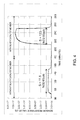
- the gas sensor 1 provided with the silver catalyst member 4 including the silver wool and a gas sensor not provided with the silver catalyst member 4 are used to measure resistance values indicated by the gas sensitive films 107 of the respective NO 2 detecting sensor elements 5, and a result of the measurements is illustrated in Fig. 4 .
- the result shows that the case of providing the silver catalyst member 4 including the silver wool exhibits a resistance value (sensitivity) as high as an approximately 10 times.
- the gas sensor 1 configured as above according to the present embodiment, even if ozone and NO 2 coexist in the sample gas, concentrations of these two substances can be measured with the single gas sensor 1.
- the detection sensitivity of the NO 2 detection sensor element 5 for NO 2 in the sample gas can be significantly improved.
- a mechanism by which the detection sensitivity of the NO 2 detecting sensor element 5 for NO 2 in the sample gas having passed through the silver catalyst member 4 is improved is not clarified at the time of the present invention; however, as the mechanism, (1) NO 2 is activated by the silver catalyst (e.g., NO 2 is further oxidized to N 2 O 5 to thereby improve electron trapping capability from the gas sensitive film 107), (2) the gas sensitive film 107 is activated by silver particles released from the catalyst, or the like is presumed.
- the sensor element 3 or 5 has the fine structure of which one side has the length of 1 to 2 mm, and therefore even if the silver catalyst member 4 is provided, the small sized gas sensor 1 can be built.
- sensitivities of the ozone detecting sensor element 3 and NO 2 detecting sensor element 5 are influenced by a flow rate, and have clarified that by increasing the flow rate of the sample gas supplied to the sensor elements 3 and 5, the sensitivities are increased.
- an experimental system 100 as illustrated in Fig. 5 is fabricated.
- the experimental system 100 is provided with, as NO 2 , N 2 , and O 2 supply sources 101, 102, and 103, high pressure cylinders in which the respective gases are filled, and the respective gases supplied from the gas supply sources are mixed in dividers 104a and 104b to achieve predetermined concentrations, and thereby regulated to a sample gas.
- the obtained sample gas (250 mL/min) passes through a main flow path 106, and is then supplied into a cell 5' provided with the NO 2 detecting sensor element 5.
- the NO 2 detecting sensor element 5 is incorporated in the cell 5' having a cylindrical shape (inner diameter ⁇ 7 mm) with being hung so as to be easily influenced by a flow rate of the sample gas.
- a needle valve 105a is provided, and the flow rate of the sample gas is regulated by the needle valve 105a.
- an exhaust path 107 that branches from the main flow path 106 and is intended to exhaust the sample gas is provided, and also provided with a needle valve 105b.
- Such an experimental system 100 is used to supply the sample gas (N 2 concentration: 80 vol%, O 2 concentration: 20 vol%) in which the NO 2 concentration is regulated to 50 ppb to the NO 2 detecting sensor element 5 while adjusting the needle valve 105a to vary the flow rate of the sample gas. While varying the flow rate of the sample gas from 100, to 50, to 6.5, to 20 mL/min, sensor response is continuously measured to obtain sensitivities (resistance values) of the NO 2 detecting sensor element 5 at the respective flow rates.
- gas analyzer 10 configured with use of the gas sensor 1 according to the present embodiment is described below with reference to the drawings.
- the present gas analyzer 10 is, as illustrated in Fig. 7 , provided with: a flow path system that lets a sample gas flow or circulate; the gas sensor 1 that is provided in the flow path system and measures concentrations of ozone and NO 2 ; and an information processor 20 that collects measurement result data from the gas sensor 1 and controls flow rate regulators and the like arranged in the flow path system.
- the flow path system includes a main flow path 12 through which the sample gas flows, and the main flow path 12 is opened at an upstream end thereof as an inlet port 11 and allocated with a suction pump 18 on a most downstream side thereof.
- a filter 13 that removes dust and the like, a temperature/humidity sensor 14, a heating tube 15, the ozone detecting sensor element 3, the silver catalyst member 4, the NO 2 detecting sensor element 5, a first flow rate regulator 16a, a first flowmeter 17a, a second flow rate regulator 16b, a second flowmeter 17b, and the suction pump 18 are arranged in series in this order.
- the ozone detecting sensor element 3 and the NO 2 detecting sensor element 5 are respectively provided in cells 3' and 5', and an assembly of them and the silver catalyst member 4 corresponds to the gas sensor 1 according to the present embodiment.
- the temperature/humidity sensor 14 is one that is intended to measure a relative humidity in the introduced sample gas at an ambient temperature; further obtain an absolute humidity from a value of the relative humidity; and on the basis of a value of the absolute humidity, correct measurement result data obtained by the gas sensor 1.
- the heating tube 15 is one that is intended to heat the sample gas, for example, from a room temperature to approximately 60 °C, and has a length of, for example, approximately 1 m. By letting the sample gas flow or circulate in such a long tube to gradually heat it, the sample gas can be heated to a uniform temperature. However, if, at the time when the sample gas is introduced from the inlet port 11, the sample gas is already heated to the predetermined temperature, the heating tube 15 is unnecessary.
- the heating tube 15, the ozone detecting sensor element 3, the silver catalyst member 4, and the NO 2 detecting sensor element 5 are all adjusted in temperature by an after-mentioned control part, and controlled to make measurements at a constant temperature.
- the first and second flow rate regulators 16a and 16b are ones intended to regulate a flow rate of the sample gas flowing through the main flow path 12, as which specifically needle valves are respectively used.
- the flow rate regulator 16 is not limited to the needle valve if the flow rate can be regulated, and as the flow rate regulator 16, for example, a capillary, mass flow controller, or the like may be used.
- the present gas analyzer 10 is provided with the first and second flowmeters 17a and 17b, and can thereby check the flow rate; however, for example, by providing a flowmeter outside the present gas analyzer 10, the first and second flowmeters 17a and 17b can also be omitted.
- a point between the filter 13 and the temperature/humidity sensor 14, and a point between the first flowmeter 17a and the second flow rate regulator 16b are short-circuited by a branched path 19.
- the sample gas flows through the branched path 19 joins the sample gas flowing through the main flow path 12; however, in the present embodiment, the flow rate of the sample gas flowing through the main flow path 12 is 50 to 100 mL/min, whereas the flow rate of the sample gas flowing through the branched path 19 is 500 to 1000 mL/min.
- the sample gas flowing through the main flow path 12 is pulled by the sample gas flowing through the branched path 19, on the basis of which the flow rate of the sample gas flowing through the main flow path 12 can be increased. Accordingly, by providing such a branched path 19, high speed response becomes possible.
- the main flow path 12 and the branched path 19 are respectively formed of fluororesin tubes that are superior in corrosion resistance, and also filter 13 is applied with fluororesin coating.
- the information processor 20 is a general-purpose or dedicated device provided with, in addition to a CPU, input means such as a memory and a keyboard, output means such as a display, and the like. Also, by, according to a predetermined program stored in the memory, collaboratively operating the CPU and its peripheral devices, the information processor 20 fulfills functions as the control part that performs open/close control of the valves provided in the flow path system and temperature control of the heaters; a calculation processing part that applies predetermined calculation processing to pieces of measurement result data obtained from the temperature/humidity sensor 14 and gas sensor 1 to calculate concentrations of ozone and NO 2 in the sample gas; and the like.
- FIG. 8 A second embodiment of the present invention is described below with reference to Fig. 8 . Note that, in the following, the description is provided with focusing on differences from the first embodiment.
- a gas sensor 1 according to the second embodiment is, as illustrated in Fig. 8 , further provided with, on a downstream side of an NO 2 detecting sensor element 5, an oxidation catalyst member 6 and an NO detecting sensor element 7 (corresponding to a third semiconductor gas sensor element) that are sequentially provided from an upstream side.
- the oxidation catalyst member 6 includes platinum (Pt) wool, manganese oxide ( ⁇ -MnO 2 ) wool, or the like, and is one intended to oxidize NO in a sample gas to NO 2 .
- the same semiconductor gas sensor element as an ozone detecting sensor element 3 and an NO 2 detecting sensor element 5 is used.
- NO in the sample gas having passed through the oxidation catalyst member 6 is oxidized to NO 2 , and therefore in the NO detecting sensor element 7, both of NO and NO 2 originally contained in the sample gas are detected as NO 2 . For this reason, by subtracting a resistance value indicated by the NO 2 detecting sensor element 5 from a resistance value indicated by the NO detecting sensor element 7, a concentration of NO can be measured.
- the gas sensor 1 configured as above according to the present embodiment, even if ozone, NO 2 , and NO coexist in the sample gas, concentrations of these three substances can be measured with the single gas sensor 1.
- a third embodiment of the present invention is described below with reference to Fig. 9 . Note that, in the following, the description is provided with focusing on differences from the first embodiment.
- a gas sensor 1 according to the third embodiment is configured such that, as illustrated in Fig. 9 , the ozone detecting sensor element 3 is not provided, but in parallel with a silver catalyst member 4, a second flow path 9 that makes a sample gas directly reach an NO 2 detecting sensor element 5 is provided, and at a branching point between a main flow path 2 and the second flow path 9, a first switching valve 8 is provided to be able to alternately switch between flow of the sample gas into the silver catalyst member 4 and flow of the sample gas into the second flow path 9 at intervals of, for example, a few minutes.
- the gas sensor 1 by switching the first switching valve 8 such that the sample gas passes through the silver catalyst member 4, ozone in the sample gas having passed through the silver catalyst member 4 is reduced to oxygen, on the basis of which ozone is removed from the sample gas, and therefore NO 2 can be detected with the NO 2 detecting sensor element 5.
- the first switching valve 8 by switching the first switching valve 8 such that the sample gas passes through the second flow path 9, ozone can be detected with the NO 2 detecting sensor element 5.
- the gas sensor 1 configured as above according to the present embodiment, by switching the first switching valve 8, even if ozone and NO 2 coexist in the sample gas, concentrations of these two substances can be measured only with the single NO 2 detecting sensor element 5.
- a fourth embodiment of the present invention is described below with reference to Fig. 10 . Note that, in the following, the description is provided with focusing on differences from the third embodiment.
- a gas sensor 1 according to the fourth embodiment as illustrated in Fig. 10 , between the silver catalyst member 4 and the NO 2 detecting sensor element 5 in the gas sensor 1 according to the third embodiment, and on a downstream side of a joining point between a main flow path 2 and a second flow path 9, an oxidation catalyst member 6 is further provided, and in parallel with the oxidation catalyst member 6, there is provided a third flow path 11 that makes a sample gas directly reach an NO 2 detecting sensor element 5 without passing the sample gas through the oxidation catalyst member 6.
- the gas sensor 1 is configured such that, at a branching point between the main flow path 2 passing through the oxidation catalyst member 6 and the third flow path 11, a second switching valve 10 is provided to be able to alternately switch between flow of the sample gas into the oxidation catalyst member 6 and flow of the sample gas into the third flow path 11 at intervals of, for example, a few minutes.
- NO in the sample gas having passed through the oxidation catalyst member 6 is oxidized to NO 2 , and therefore in the NO 2 detecting sensor element 5, both of NO and NO 2 originally contained in the sample gas are detected as NO 2 .
- NO 2 or ozone can be detected in the NO 2 detecting sensor element 5.
- the gas sensor 1 configured as above according to the present embodiment, by switching the switching valves 8 and 10, even if ozone, NO 2 , and NO coexist in the sample gas, concentrations of these three substances can be measured only with the single NO 2 detecting sensor element 5.
- the respective substances contained in the sample gas are brought into contact with the gas sensitive film 107 by diffusion; however, as illustrated in Fig. 11 , it may be configured such that the sample gas is directly blown to the gas sensitive film 107.
- the silver catalyst member 4 is provided inside with catalyst flow paths, for example gaps, through which the sample gas can pass, and not limited to the silver wool but if at least on surfaces of the catalyst flow paths, silver is exposed, any substance may be employed, for example, a porous carrier carrying and supporting silver particles, or the like may be employed.
- the gas sensor 1 is one in which, by making the sample gas having passed through the silver catalyst member 4 serve as a test target gas for the NO 2 detecting sensor element 5, a detection sensitivity of the NO 2 detecting sensor element 5 for NO 2 in the sample gas is significantly improved, and therefore the gas sensitive film 107 of the NO 2 detecting sensor element 5 is not limited to one including monoclinic WO 3 containing hexagonal WO 3 crystal, but there may be employed a gas sensitive film 107 including only monoclinic WO 3 , which is inferior in detection sensitivity for low concentration NO 2 as compared with the gas sensitive film 107 including monoclinic WO 3 containing hexagonal WO 3 crystal.
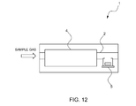
- the gas sensor 1 may have a configuration in which, as illustrated in Fig. 12 , from the gas sensor 1 according to the first embodiment, the ozone detecting sensor element 3 is removed.
Landscapes
- Chemical & Material Sciences (AREA)
- Life Sciences & Earth Sciences (AREA)
- Engineering & Computer Science (AREA)
- Health & Medical Sciences (AREA)
- Medicinal Chemistry (AREA)
- Food Science & Technology (AREA)
- Combustion & Propulsion (AREA)
- Physics & Mathematics (AREA)
- Analytical Chemistry (AREA)
- Biochemistry (AREA)
- General Health & Medical Sciences (AREA)
- General Physics & Mathematics (AREA)
- Immunology (AREA)
- Pathology (AREA)
- Investigating Or Analyzing Materials By The Use Of Fluid Adsorption Or Reactions (AREA)
Applications Claiming Priority (2)
| Application Number | Priority Date | Filing Date | Title |
|---|---|---|---|
| JP2009201301 | 2009-09-01 | ||
| JP2010158694A JP2011075545A (ja) | 2009-09-01 | 2010-07-13 | ガスセンサ |
Publications (1)
| Publication Number | Publication Date |
|---|---|
| EP2293060A2 true EP2293060A2 (de) | 2011-03-09 |
Family
ID=43478311
Family Applications (1)
| Application Number | Title | Priority Date | Filing Date |
|---|---|---|---|
| EP10174742A Withdrawn EP2293060A2 (de) | 2009-09-01 | 2010-08-31 | Gassensor |
Country Status (4)
| Country | Link |
|---|---|
| US (1) | US20110048108A1 (de) |
| EP (1) | EP2293060A2 (de) |
| JP (1) | JP2011075545A (de) |
| CN (1) | CN102004124A (de) |
Cited By (2)
| Publication number | Priority date | Publication date | Assignee | Title |
|---|---|---|---|---|
| WO2019154779A1 (en) * | 2018-02-06 | 2019-08-15 | Airlabs Bv | Ozone and/or nitrogen dioxide sensing apparatus |
| FR3104721A1 (fr) * | 2019-12-17 | 2021-06-18 | Rubix S&I | Dispositif et procédé d’identification d’un mélange gazeux |
Families Citing this family (15)
| Publication number | Priority date | Publication date | Assignee | Title |
|---|---|---|---|---|
| JP5822348B2 (ja) * | 2011-11-04 | 2015-11-24 | フィガロ技研株式会社 | ガスセンサ |
| CN104792846B (zh) * | 2014-12-10 | 2017-10-03 | 中国第一汽车股份有限公司 | 可用于nox传感器的多功能防护罩及其涂层制备方法 |
| US10509007B1 (en) * | 2014-12-18 | 2019-12-17 | Aeroqual Limited | Measurement of gases |
| US10126165B2 (en) * | 2015-07-28 | 2018-11-13 | Carrier Corporation | Radiation sensors |
| CN105044292B (zh) * | 2015-08-14 | 2016-11-30 | 泰州市中环分析仪器有限公司 | 配置臭氧热分解装置的氮元素分析仪 |
| US10993657B1 (en) * | 2015-12-30 | 2021-05-04 | Halo Wearables, Llc | Wearable hydration monitor sensors |
| EP3223005A1 (de) * | 2016-03-22 | 2017-09-27 | Alphasense Limited | Elektrochemische gasmessvorrichtung und verfahren |
| CN106442873B (zh) * | 2016-08-29 | 2019-05-03 | 河北先河环保科技股份有限公司 | 一种voc监测仪用的传感器切换机构 |
| US20190234896A1 (en) * | 2016-09-21 | 2019-08-01 | Sensirion Ag | Resistive metal oxide gas sensor coated with a fluoropolymer filter |
| EP3422124A1 (de) * | 2017-06-30 | 2019-01-02 | SUEZ Groupe | Verfahren zur steuerung einer ozonerzeugungswaschmaschine |
| CN108732212B (zh) * | 2018-05-23 | 2020-12-15 | 哈尔滨工程大学 | 一种多效应检测集成气体传感器制造方法的制造方法、传感器及其应用 |
| JP7313678B2 (ja) * | 2019-09-10 | 2023-07-25 | 国立研究開発法人物質・材料研究機構 | アルデヒド検知センサ、および、それを用いたシステム |
| US11162928B2 (en) * | 2019-11-04 | 2021-11-02 | Invensense, Inc. | Humidity correction method in thermistor based gas sensing platform |
| WO2021123864A1 (en) * | 2019-12-16 | 2021-06-24 | Aeroqual Ltd. | Improved measurement of gases |
| CN113514515A (zh) * | 2021-08-20 | 2021-10-19 | 盛密科技(上海)有限公司 | 气体浓度检测器和无需偏压的气体浓度检测方法 |
Citations (2)
| Publication number | Priority date | Publication date | Assignee | Title |
|---|---|---|---|---|
| JP2007064908A (ja) | 2005-09-02 | 2007-03-15 | Ritsumeikan | 半導体式薄膜ガスセンサ |
| WO2009034843A1 (ja) | 2007-09-11 | 2009-03-19 | The Ritsumeikan Trust | 半導体式ガスセンサ及びその製造方法 |
Family Cites Families (4)
| Publication number | Priority date | Publication date | Assignee | Title |
|---|---|---|---|---|
| JPS54141375A (en) * | 1978-04-26 | 1979-11-02 | Akira Kuwata | Ozone absorber |
| US20020159215A1 (en) * | 1999-12-06 | 2002-10-31 | Siess Harold Edward | Protecting transmissive surfaces |
| US6796165B2 (en) * | 2002-11-18 | 2004-09-28 | Southwest Research Institute | Apparatus and method for real-time measurement of mass, size and number of solid particles of particulate matter in engine exhaust |
| US7654129B2 (en) * | 2005-05-17 | 2010-02-02 | Honeywell International Inc. | Sensor with an analyte modulator |
-
2010
- 2010-07-13 JP JP2010158694A patent/JP2011075545A/ja active Pending
- 2010-08-25 CN CN2010102623742A patent/CN102004124A/zh active Pending
- 2010-08-31 EP EP10174742A patent/EP2293060A2/de not_active Withdrawn
- 2010-09-01 US US12/873,558 patent/US20110048108A1/en not_active Abandoned
Patent Citations (2)
| Publication number | Priority date | Publication date | Assignee | Title |
|---|---|---|---|---|
| JP2007064908A (ja) | 2005-09-02 | 2007-03-15 | Ritsumeikan | 半導体式薄膜ガスセンサ |
| WO2009034843A1 (ja) | 2007-09-11 | 2009-03-19 | The Ritsumeikan Trust | 半導体式ガスセンサ及びその製造方法 |
Cited By (3)
| Publication number | Priority date | Publication date | Assignee | Title |
|---|---|---|---|---|
| WO2019154779A1 (en) * | 2018-02-06 | 2019-08-15 | Airlabs Bv | Ozone and/or nitrogen dioxide sensing apparatus |
| FR3104721A1 (fr) * | 2019-12-17 | 2021-06-18 | Rubix S&I | Dispositif et procédé d’identification d’un mélange gazeux |
| WO2021122390A1 (fr) | 2019-12-17 | 2021-06-24 | Rubix S&I | Dispositif et procédé d'identification d'un mélange gazeux |
Also Published As
| Publication number | Publication date |
|---|---|
| JP2011075545A (ja) | 2011-04-14 |
| US20110048108A1 (en) | 2011-03-03 |
| CN102004124A (zh) | 2011-04-06 |
Similar Documents
| Publication | Publication Date | Title |
|---|---|---|
| US20110048108A1 (en) | Gas sensor | |
| US8920627B2 (en) | Selective detector for carbon monoxide | |
| US20180024089A1 (en) | Nanoparticle-Based Gas Sensors and Methods of Using the Same | |
| US7323343B2 (en) | Nitrogen monoxide, nitrogen dioxide and ozone determination in air | |
| US6435003B1 (en) | Method of identifying a gas and associated apparatus | |
| US7062952B2 (en) | Combustible gas detector having flow-through sensor container and method for measuring such gases | |
| US8869591B2 (en) | Method and apparatus for vapor signature with heat differential | |
| CN108779926A (zh) | 空气净化器及空气净化方法 | |
| JP2025108578A (ja) | センサ部品と酸化部品とを備えたガス検知装置およびガス検知方法 | |
| KR200453056Y1 (ko) | 휘발성 유기화합물 검출기 | |
| KR102330982B1 (ko) | 날숨 온도 측정 기능을 구비한 음주측정기 | |
| Wiegleb | Physical-Chemical Gas Sensors | |
| RU2536315C1 (ru) | Устройство для определения концентрации кислорода и водорода в газовой среде | |
| CN210572098U (zh) | 用于测量气体中油蒸汽或其它烃类含量的测量装置 | |
| Schambach et al. | Micromachined mercury sensor | |
| KR101133820B1 (ko) | 전기화학적 센서 | |
| RU2716163C1 (ru) | Способ контроля веществ в водных растворах | |
| RU2740737C1 (ru) | Каскадный полупроводниковый детектор для газовой хроматографии | |
| RU57012U1 (ru) | Датчик для измерения концентрации компонентов анализируемой газовой среды | |
| JPH1164264A (ja) | ガス濃度検出装置及びその方法 | |
| Röck et al. | Metal oxide gas sensor arrays: Geometrical design and selectivity | |
| RU2440567C1 (ru) | Датчик содержания сернистого газа в воздухе | |
| WO2026033251A1 (en) | Gas sensing system | |
| Maksimovich et al. | Device with semiconductor gas sensor for alcohol vapor detection in an exhaled air sample | |
| Song et al. | The fabrication of novel micro hot-wire sensor |
Legal Events
| Date | Code | Title | Description |
|---|---|---|---|
| PUAI | Public reference made under article 153(3) epc to a published international application that has entered the european phase |
Free format text: ORIGINAL CODE: 0009012 |
|
| AK | Designated contracting states |
Kind code of ref document: A2 Designated state(s): AL AT BE BG CH CY CZ DE DK EE ES FI FR GB GR HR HU IE IS IT LI LT LU LV MC MK MT NL NO PL PT RO SE SI SK SM TR |
|
| AX | Request for extension of the european patent |
Extension state: BA ME RS |
|
| STAA | Information on the status of an ep patent application or granted ep patent |
Free format text: STATUS: THE APPLICATION HAS BEEN WITHDRAWN |
|
| 18W | Application withdrawn |
Effective date: 20120611 |