EP2293348A2 - Dispositif photovoltaïque et son procédé de fabrication - Google Patents
Dispositif photovoltaïque et son procédé de fabrication Download PDFInfo
- Publication number
- EP2293348A2 EP2293348A2 EP10175163A EP10175163A EP2293348A2 EP 2293348 A2 EP2293348 A2 EP 2293348A2 EP 10175163 A EP10175163 A EP 10175163A EP 10175163 A EP10175163 A EP 10175163A EP 2293348 A2 EP2293348 A2 EP 2293348A2
- Authority
- EP
- European Patent Office
- Prior art keywords
- unit cell
- photovoltaic device
- intermediate reflector
- equal
- metallic nanoparticles
- Prior art date
- Legal status (The legal status is an assumption and is not a legal conclusion. Google has not performed a legal analysis and makes no representation as to the accuracy of the status listed.)
- Withdrawn
Links
Images
Classifications
-
- H—ELECTRICITY
- H10—SEMICONDUCTOR DEVICES; ELECTRIC SOLID-STATE DEVICES NOT OTHERWISE PROVIDED FOR
- H10F—INORGANIC SEMICONDUCTOR DEVICES SENSITIVE TO INFRARED RADIATION, LIGHT, ELECTROMAGNETIC RADIATION OF SHORTER WAVELENGTH OR CORPUSCULAR RADIATION
- H10F10/00—Individual photovoltaic cells, e.g. solar cells
- H10F10/10—Individual photovoltaic cells, e.g. solar cells having potential barriers
- H10F10/17—Photovoltaic cells having only PIN junction potential barriers
- H10F10/172—Photovoltaic cells having only PIN junction potential barriers comprising multiple PIN junctions, e.g. tandem cells
-
- H—ELECTRICITY
- H10—SEMICONDUCTOR DEVICES; ELECTRIC SOLID-STATE DEVICES NOT OTHERWISE PROVIDED FOR
- H10F—INORGANIC SEMICONDUCTOR DEVICES SENSITIVE TO INFRARED RADIATION, LIGHT, ELECTROMAGNETIC RADIATION OF SHORTER WAVELENGTH OR CORPUSCULAR RADIATION
- H10F19/00—Integrated devices, or assemblies of multiple devices, comprising at least one photovoltaic cell covered by group H10F10/00, e.g. photovoltaic modules
- H10F19/30—Integrated devices, or assemblies of multiple devices, comprising at least one photovoltaic cell covered by group H10F10/00, e.g. photovoltaic modules comprising thin-film photovoltaic cells
- H10F19/31—Integrated devices, or assemblies of multiple devices, comprising at least one photovoltaic cell covered by group H10F10/00, e.g. photovoltaic modules comprising thin-film photovoltaic cells having multiple laterally adjacent thin-film photovoltaic cells deposited on the same substrate
- H10F19/33—Patterning processes to connect the photovoltaic cells, e.g. laser cutting of conductive or active layers
-
- H—ELECTRICITY
- H10—SEMICONDUCTOR DEVICES; ELECTRIC SOLID-STATE DEVICES NOT OTHERWISE PROVIDED FOR
- H10F—INORGANIC SEMICONDUCTOR DEVICES SENSITIVE TO INFRARED RADIATION, LIGHT, ELECTROMAGNETIC RADIATION OF SHORTER WAVELENGTH OR CORPUSCULAR RADIATION
- H10F19/00—Integrated devices, or assemblies of multiple devices, comprising at least one photovoltaic cell covered by group H10F10/00, e.g. photovoltaic modules
- H10F19/50—Integrated devices comprising at least one photovoltaic cell and other types of semiconductor or solid-state components
-
- H—ELECTRICITY
- H10—SEMICONDUCTOR DEVICES; ELECTRIC SOLID-STATE DEVICES NOT OTHERWISE PROVIDED FOR
- H10F—INORGANIC SEMICONDUCTOR DEVICES SENSITIVE TO INFRARED RADIATION, LIGHT, ELECTROMAGNETIC RADIATION OF SHORTER WAVELENGTH OR CORPUSCULAR RADIATION
- H10F77/00—Constructional details of devices covered by this subclass
- H10F77/30—Coatings
- H10F77/306—Coatings for devices having potential barriers
- H10F77/311—Coatings for devices having potential barriers for photovoltaic cells
- H10F77/315—Coatings for devices having potential barriers for photovoltaic cells the coatings being antireflective or having enhancing optical properties
-
- H—ELECTRICITY
- H10—SEMICONDUCTOR DEVICES; ELECTRIC SOLID-STATE DEVICES NOT OTHERWISE PROVIDED FOR
- H10F—INORGANIC SEMICONDUCTOR DEVICES SENSITIVE TO INFRARED RADIATION, LIGHT, ELECTROMAGNETIC RADIATION OF SHORTER WAVELENGTH OR CORPUSCULAR RADIATION
- H10F77/00—Constructional details of devices covered by this subclass
- H10F77/40—Optical elements or arrangements
- H10F77/42—Optical elements or arrangements directly associated or integrated with photovoltaic cells, e.g. light-reflecting means or light-concentrating means
- H10F77/48—Back surface reflectors [BSR]
-
- Y—GENERAL TAGGING OF NEW TECHNOLOGICAL DEVELOPMENTS; GENERAL TAGGING OF CROSS-SECTIONAL TECHNOLOGIES SPANNING OVER SEVERAL SECTIONS OF THE IPC; TECHNICAL SUBJECTS COVERED BY FORMER USPC CROSS-REFERENCE ART COLLECTIONS [XRACs] AND DIGESTS
- Y02—TECHNOLOGIES OR APPLICATIONS FOR MITIGATION OR ADAPTATION AGAINST CLIMATE CHANGE
- Y02E—REDUCTION OF GREENHOUSE GAS [GHG] EMISSIONS, RELATED TO ENERGY GENERATION, TRANSMISSION OR DISTRIBUTION
- Y02E10/00—Energy generation through renewable energy sources
- Y02E10/50—Photovoltaic [PV] energy
- Y02E10/52—PV systems with concentrators
-
- Y—GENERAL TAGGING OF NEW TECHNOLOGICAL DEVELOPMENTS; GENERAL TAGGING OF CROSS-SECTIONAL TECHNOLOGIES SPANNING OVER SEVERAL SECTIONS OF THE IPC; TECHNICAL SUBJECTS COVERED BY FORMER USPC CROSS-REFERENCE ART COLLECTIONS [XRACs] AND DIGESTS
- Y02—TECHNOLOGIES OR APPLICATIONS FOR MITIGATION OR ADAPTATION AGAINST CLIMATE CHANGE
- Y02E—REDUCTION OF GREENHOUSE GAS [GHG] EMISSIONS, RELATED TO ENERGY GENERATION, TRANSMISSION OR DISTRIBUTION
- Y02E10/00—Energy generation through renewable energy sources
- Y02E10/50—Photovoltaic [PV] energy
- Y02E10/548—Amorphous silicon PV cells
Definitions
- This embodiment relates to a photovoltaic device and a method for manufacturing the same.
- the sunlight incident on the surface of the earth has an electric power of 120,000 TW.
- a photovoltaic device having a photoelectric conversion efficiency of 10% covers only 0.16% of the land surface of the earth, it is possible to generate electric power of 20 TW that is twice as much as the amount of energy globally consumed during one year.
- the bulk-type silicon photovoltaic device occupies a 90% of the photovoltaic device market share.
- the bulk-type silicon photovoltaic device includes a single-crystalline silicon photovoltaic device and a multi-crystalline or a poly-crystalline silicon photovoltaic device and the like.
- productivity of a solar-grade silicon wafer which is the main material of the photovoltaic device is not able to fill the explosive demand thereof, so the solar-grade silicon wafer is globally in short supply. Therefore, this shortage of the solar-grade silicon wafer is a huge threatening factor in reducing the manufacturing cost of a photovoltaic device.
- a thin-film silicon photovoltaic device including a light absorbing layer based on a hydrogenated amorphous silicon (a-Si:H) allows to reduce a thickness of a silicon layer equal to or less than 1/100 as large as that of a silicon wafer of the bulk-type silicon photovoltaic device. Also, it makes possible to manufacture a large area photovoltaic device at a lower cost.
- a single-junction thin-film silicon photovoltaic device is limited in its achievable performance. Accordingly, a double junction thin-film silicon photovoltaic device or a triple junction thin-film silicon photovoltaic device having a plurality of stacked unit cells has been developed, pursuing high stabilized efficiency.
- the double junction or the triple junction thin-film silicon photovoltaic device is referred to as a tandem-type photovoltaic device.
- the open circuit voltage of the tandem-type photovoltaic device corresponds to a sum of each unit cell's open circuit voltage.
- Short circuit current is determined by a minimum value among the short circuit currents of the unit cells.
- tandem-type photovoltaic device research is being devoted to an intermediate reflector which is capable of improving efficiency by enhancing internal light reflection between the unit cells.
- One aspect of this invention is a method for manufacturing a photovoltaic device.
- the method comprising: forming a first electrode on a substrate; forming a first unit cell converting light into electricity on the first electrode; forming an intermediate reflector on the first unit cell, the intermediate reflector including metallic nanoparticles arranged therein; and forming a second unit cell converting light into electricity on the intermediate reflector.
- the photovoltaic device includes: a first electrode placed on a substrate; a first unit cell placed on the first electrode and converting light into electricity; an intermediate reflector placed on the first unit cell and including metallic nanoparticles arranged therein ; and a second unit cell placed on the intermediate reflector and converting light into electricity.
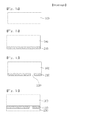
- Figs. 1a to 1h show a method for manufacturing a photovoltaic device according to the embodiment of the present invention.
- a photovoltaic device according to an embodiment of the present invention and a method for manufacturing the photovoltaic device will be described with reference to the drawings.
- a photovoltaic device may include a double junction structure and a triple junction structure and the like.
- a photovoltaic device having the double junction structure will be described as an example.
- Figs. 1a to 1h show a method for manufacturing a photovoltaic device according to the embodiment of the present invention.
- the substrate 100 may include an insulating transparent substrate and an insulating opaque substrate.
- the insulating transparent substrate may be included in a p-i-n type photovoltaic device.
- the insulating opaque substrate may be included in an n-i-p type photovoltaic device.
- the pi-n type photovoltaic device and the n-i-p type photovoltaic device will be described later in detail.
- a first electrode 210 is formed on the substrate 100.
- the first electrode 210 may be formed by using chemical vapor deposition (CVD) method and comprises a transparent conductive oxide (TCO) such as Tin dioxide (SnO 2 ) and Zinc Oxide (ZnO) and the like.
- TCO transparent conductive oxide
- ZnO Zinc Oxide
- the first electrode 210 may include opaque conductive material.
- the first electrode 210 is scribed by irradiating a laser beam from the side of the first electrode 210 or the substrate 100.
- a first separation groove 220 is hereby formed in the first electrode 210. That is, since the first separation groove 220 penetrates through the first electrode 210, short circuits between the adjacent first electrodes 210 are avoided.
- a first unit cell 230 is formed on the first electrode 210 by using CVD method.
- the first unit cell 230 converts light into electricity and includes a p-type semiconductor layer, an intrinsic semiconductor layer and an n-type semiconductor layer.
- source gas including silicon such as SiH 4
- doping gas including group 3 elements such as B 2 H 6
- the p-type semiconductor layer is formed by using CVD method.
- the intrinsic semiconductor layer is formed by using CVD method after source gas including silicon is injected into a reaction chamber. Doping gas such as PH 3 including group 5 elements and source gas including silicon are injected together, and then the n-type semiconductor layer is formed by using CVD method.
- a p-i-n type unit cell in which the p-type semiconductor layer, the intrinsic semiconductor layer and the n-type semiconductor layer are sequentially stacked in the order specified or a n-i-p type unit cell in which the n-type semiconductor layer, the intrinsic semiconductor layer and the p-type semiconductor layer are sequentially stacked in the order specified may be formed on the first electrode 210.
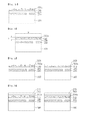
- reflective metallic nanoparticles are arranged on the first electrode 210.
- surface plasmon resonance occurs and so light intensity can be enhanced. The reason will be described later in detail that the efficiency of the photovoltaic device is increased due to the surface plasmon resonance by the metallic nanoparticles 240.
- the metallic nanoparticles are arranged by using either a vacuum deposition method, for example, a chemical vapor deposition method and a sputtering method, etc., or an arrangement method at a room temperature, for example, a spray method and a spin coating method, etc. Accordingly, an intermediate reflector 250a including the metallic nanoparticles is formed.
- the spray method for arranging the metallic nanoparticles is performed by spraying volatile liquid such as methanol, ethanol and isopropyl alcohol, etc., with a sprayer.
- the metallic nanoparticles may be arranged as shown in Fig. 1e , Fig. If shows that the metallic nanoparticles are embedded into a metal oxide film, an oxide film, a nitride film or a carbon alloy so that an intermediate reflector 250b including the metallic nanoparticles, and the metal oxide film, the oxide film, the nitride film or the carbon alloy.
- the intermediate reflector 250b shown in Fig. If may be formed by arranging the metallic nanoparticles on the first unit cell 230, and then covering the metallic nanoparticles with a metal oxide film, an oxide film, a nitride film or a carbon alloy through vacuum deposition.
- the intermediate reflector 250b may be also formed by forming a metal oxide film, an oxide film, a nitride film or a carbon alloy on the first unit cell 230 through vacuum deposition, arranging the metallic nanoparticles on the metal oxide film, the oxide film, the nitride film or the carbon alloy, and then covering the metallic nanoparticles with another metal oxide film, another oxide film, another nitride film or another carbon alloy through vacuum deposition.
- the metallic nanoparticles can be stably arranged in the metal oxide film, the oxide film, the nitride film or the carbon alloy.
- the metallic nanoparticles may include at least one of Gold (Au), Silver (Ag), Aluminum (Al), Platinum (Pt), Copper (Cu), Nickel (Ni), Chromium (Cr), Zinc (Zn), Titanium (Ti) and Tin (Sn).
- the metallic nanoparticles may include metallic oxide such as Zinc Oxide (ZnO), Indium Tin Oxide (ITO), Indium Zinc Oxide (IZO), Tin Dioxide (SnO 2 ), Aluminum Oxide (Al 2 O 3 ) or Magnesium Oxide (MgO).
- a second unit cell 260 converting light into electricity is formed on the intermediate reflector 250a and 250b.
- the second unit cell 260 includes a p-type semiconductor layer, an intrinsic semiconductor layer and an n-type semiconductor layer.
- the second unit cell 260 on the intermediate reflector 250a and 250b may be either of a p-i-n type unit cell in which the p-type semiconductor layer, the intrinsic semiconductor layer and the n-type semiconductor layer are sequentially stacked in the order specified or a n-i-p type unit cell in which the n-type semiconductor layer, the intrinsic semiconductor layer and the p-type semiconductor layer are sequentially stacked in the order specified.
- uniformity of the p-type semiconductor layer of the p-i-n type second unit cell 260 or the n-type semiconductor layer of the n-i-p type unit cell 260, which is contacting with the intermediate reflector 250b, may be superior to that of the p-type semiconductor layer or the n-type semiconductor layer of the second unit cell 260 formed on the intermediate reflector 250a of Fig. 1e .
- the refractive index of the intermediate reflector 250b may be equal to or more than 1.7 and equal to or less than 2.2.
- the refractive index of the intermediate reflector 250b is equal to or more than 1.7, the conductivity thereof increases.
- a fill factor (FF) of a multi junction photovoltaic device is improved and so efficiency becomes higher.
- the refractive index of the intermediate reflector 250b is equal to or less than 2.2, light having a wavelength from 500 nm to 700 nm is easily reflected so that the short circuit current of a unit cell which is closest to the light incident side, that is, a unit cell on which light is first incident increases. As a result, efficiency is enhanced.
- a second electrode 270 is formed on the second unit cell 260.
- the metallic nanoparticles of the intermediate reflectors 250a and 250b may enhance light intensity through surface plasmon resonance. That is, due to the surface plasmon of the metallic nanoparticles, light with a wavelength equal to or greater than 800 nm is amplified around the metallic nanoparticles by an enhanced electromagnetic field.
- a unit cell which is closest to the light incident side generally absorbs light with a short wavelength.
- a unit cell which is farthest from the light incident side generally absorbs light with a long wavelength. Therefore, since the metallic nanoparticles enhance the intensity of light with a long wavelength, the amount of current generated by the unit cell which is farthest from the light incident side may be increased even in the case of that the intrinsic semiconductor layer of the unit cell does not become thicker.
- a unit cell which is closest to the light incident side corresponds to the first unit cell 230 and a unit cell which is farthest from the light incident side corresponds to the second unit cell 260.
- a unit cell which is closest to the light incident side corresponds to the second unit cell 260 and a unit cell which is farthest from the light incident side corresponds to the first unit cell 230.
- the metallic nanoparticles reflect a part of the incident light back to the unit cell on which light is first incident, and so it makes current generation of the unit cell on which light is first incident increase.
- the metallic nanoparticles may have a diameter equal to or more than 5 nm and equal to or less than 100 nm. Further, in order to increase the intensity of light with a wavelength equal to or greater than 800 nm, the diameter of the metallic nanoparticles may be equal to or more than 20 nm and equal to or less than 60 nm.
- the intermediate reflector 250b may include a metal oxide film, an oxide film, a nitride film or a carbon alloy in which metallic nanoparticles are embedded. Since the metallic nanoparticles are dispersed in the metal oxide film, the oxide film, the nitride film or the carbon alloy, electric current can hardly flow through the metallic nanoparticles. As a result, it is possible to avoid a leakage current through the intermediate reflector 250b.
- n-type impurities such as Phosphine (PH 3 ) or p-type impurities such as Boron (B) may be doped in the metal oxide film, the oxide film, the nitride film or the carbon alloy of the intermediate reflector 250b.
- the width (w) of the intermediate reflector 250b is much greater than the thickness (t) of the intermediate reflector 250b. Therefore, when the n-type impurities or the p-type impurities are doped, the vertical conductivity is improved. However, a horizontal conductivity thereof is not so high that a leakage current can flow through the intermediate reflector 250b.
- the intermediate reflector 250b may include hydrogenated n-type silicon oxide (n-SiO:H), hydrogenated n-type silicon carbide (n-SiC:H) or hydrogenated n-type silicon nitride (n-SiN:H). Also, the intermediate reflector 250b may include hydrogenated n-type nanocrystalline silicon oxide (n - nc - SiO:H), hydrogenated n-type nanocrystalline silicon carbide (n - nc - SiC:H) or hydrogenated n-type nanocrystalline silicon nitride (n - nc - SiN:H), which has the vertical conductivity superior to that of an amorphous silicon based material.
- n-SiO:H hydrogenated n-type silicon oxide
- n-SiC:H hydrogenated n-type silicon carbide
- n-SiN:H hydrogenated n-type silicon nitride
- the thickness of the intermediate reflector 250b may be equal to or more than 30 nm and equal to or less than 2000 nm. To match a refractive index between the intermediate reflector 250b and the unit cell on which light is first incident, the thickness of the intermediate reflector 250b may be equal to or more than 30 nm. When the thickness of the intermediate reflector 250b is equal to or less than 2000 nm, the light is prevented from being excessively absorbed by the intermediate reflector 250b. When the thickness of the intermediate reflector 250b is equal to or more than 50 nm and equal to or less than 100 nm, the refractive index matching is easily achieved and light is prevented from being excessively absorbed.
- a plane fill factor of the metallic nanoparticles may be equal to or more than 0.1 % and equal to or less than 10 %.
- the plane fill factor corresponds to a ratio of an area that the metallic nanoparticles occupy to the plane unit area of the intermediate reflector 250b.
- the plane fill factor of the metallic nanoparticles may be equal to or more than 0.1 % so as to generate the surface plasmon resonance.
- the plane fill factor of the metallic nanoparticles may be equal to or less than 10 % so as to prevent the amount of light which the metallic nanoparticles reflect or absorb from being excessively increased.
- the photovoltaic device includes the intermediate reflector 250a and 250b so as to increase the efficiency of a tandem structure including a plurality of the unit cells. It is possible to provide even better efficiency by controlling the electric currents of the plurality of the unit cells in addition to introducing the intermediate reflector 250a and 250b.
- the operating temperature of the photovoltaic device is an important factor in designing current matching among the plurality of the unit cells of the photovoltaic device having a tandem structure.
- a photovoltaic device installed in a region having high temperature or strong ultraviolet radiation is designed such that short circuit current of the photovoltaic device is determined by short circuit current of the unit cell which is closest to the light incident side among the unit cells of the photovoltaic device.
- the photovoltaic device having its short circuit current determined by the short circuit current of the unit cell which is closest to the light incident side has low temperature coefficient (i.e., an efficiency degradation rate of the photovoltaic device according to temperature rise by 1 °C). That is, the temperature rise of the photovoltaic device has small influence on the efficiency degradation thereof.
- a photovoltaic device installed in a region having low temperature or small amount of ultraviolet radiation is designed such that short circuit current of the photovoltaic device is determined by short circuit current of the unit cell which is farthest from the light incident side among the unit cells of the photovoltaic device. Even though the photovoltaic device having its short circuit current determined by the short circuit current of the unit cell which is farthest from the light incident side has high temperature coefficient (i.e., an efficiency deterioration rate of the photovoltaic device according to a temperature rise by 1 °C), it has low degradation ratio.
- the photovoltaic device installed in a low temperature region is relatively less affected by the temperature coefficient
- the photovoltaic device is designed such that the short circuit current of the photovoltaic device is determined by the short circuit current of the unit cell which is farthest from the light incident side.
- a rated output (efficiency) of the photovoltaic device designed in this manner is measured indoors under standard test conditions (hereinafter, referred to as STC).
- STC standard test conditions
- the photovoltaic device when the photovoltaic device is operating, most of light energy absorbed by the photovoltaic device is converted into heat energy.
- An actual operating temperature of the photovoltaic device hereby easily becomes higher than 25 °C, i.e., the photovoltaic cell temperature under the STC. Accordingly, the temperature coefficient of the photovoltaic device causes the efficiency of the photovoltaic device to be lower than the rated efficiency of the photovoltaic device measured under the STC.
- the photovoltaic device may not achieve a desired efficiency.
- current matching design of the photovoltaic device according to the embodiment of the present invention is performed under nominal operating cell temperature obtained in a standard reference environment which is similar to the actual condition under which the photovoltaic device is installed.
- the set of standard reference environment includes the followings.
- the nominal operating cell temperature corresponds to a temperature at which the photovoltaic device mounted on an open rack operates under the standard reference environment.
- the photovoltaic device is used in a variety of actual environments. Therefore, when designing the current matching of the photovoltaic device having a tandem structure is performed under nominal operating cell temperature measured in the standard reference environment which is similar to the condition under the photovoltaic device is actually installed, it is possible to manufacture the photovoltaic device suitable for the actual installation environment.
- the thicknesses and optical band gaps of the i-type photoelectric conversion layers of the first unit cell 230 and the second unit cells 260 such that the short circuit currents of the first unit cell 230 and the second unit cell 260 are controlled, the efficiency of the photovoltaic device may be enhanced.
- the thickness and optical band gap of the i-type photoelectric conversion layer of one unit cell which is closest to the light incident side between the first unit cell 230 and the second unit cell 260 is set such that the short circuit current of the one unit cell is equal to or less than that of the other unit cell.
- the short circuit current of the photovoltaic device according to the embodiment of the present invention is determined by the short circuit current of the unit cell which is closest to the light incident side.
- the temperature coefficient becomes smaller. Therefore, although the actual temperature of the photovoltaic device becomes higher, electricity generation performance decrease due to the efficiency degradation is reduced.
- the photovoltaic device designed for making the short circuit current of one unit cell which is closest to the light incident side to be equal to or less than the short circuit current of the other unit cell is installed in a region having high temperature or strong ultraviolet rays of sunlight including intensive short wavelength rays in a blue-color range, the temperature coefficient is small. Therefore, although the actual temperature of the photovoltaic device becomes higher, the electricity generation performance decrease due to the efficiency degradation is reduced.
- the thicknesses and optical band gap of the i-type photoelectric conversion layer of one unit cell which is farthest from the light incident side between the first unit cell 230 and the second unit cell 260 is set such that the short circuit current of the other unit cell which is closest to the light incident side is equal to or less than that of the one unit cell.
- the thickness and optical band gap of the i-type photoelectric conversion layer of one unit cell which is closest to the light incident side among the first unit cell 230 and the second unit cell 260 is determined such that the short circuit current of the other unit cell is equal to or more than that of the one unit cell.
- a resulting short circuit current of the photovoltaic device is hereby determined by the short circuit current of the unit cell which is farthest from the light incident side between the first unit cell and the second unit cell.
- the electricity generation performance may be improved in that the performance improvement due to the low degradation ratio may overtake the performance deterioration due to the high temperature coefficient.
- the photovoltaic device has an excellent outdoor electricity generation performance in an environment having a circumference temperature lower than 25 °C, i.e., the STC.
- the short circuit current of the photovoltaic device can be measured under the STC.
- the short circuit current can be controlled by the determination of the thickness and the optical band gap of the i-type photoelectric conversion layer.
- the p-i-n type photovoltaic device on which light is incident in the direction from the first unit cell 230 formed on the substrate 100 to the second unit cell 260 has been described in the embodiment of the present invention. Moreover, the present invention may be applied to n-i-p type photovoltaic device on which light is incident from the opposite side to the substrate 10, that is, in the direction from the second unit cell 260 to the first unit cell 230.
- a first unit cell 230 including sequentially stacked n-type semiconductor layer, i-type intrinsic semiconductor layer and p-type semiconductor layer is formed on a first electrode 210.
- An intermediate reflector 250a and 250b is formed on the first unit cell 230.
- a second unit cell 260 including sequentially stacked n-type semiconductor layer, i-type intrinsic semiconductor layer and p-type semiconductor layer is formed on the intermediate reflector 250a and 250b.
Landscapes
- Photovoltaic Devices (AREA)
- Life Sciences & Earth Sciences (AREA)
- Sustainable Development (AREA)
- Engineering & Computer Science (AREA)
- Sustainable Energy (AREA)
Applications Claiming Priority (1)
| Application Number | Priority Date | Filing Date | Title |
|---|---|---|---|
| KR1020090083299A KR101074290B1 (ko) | 2009-09-04 | 2009-09-04 | 광기전력 장치 및 광기전력 장치의 제조 방법 |
Publications (2)
| Publication Number | Publication Date |
|---|---|
| EP2293348A2 true EP2293348A2 (fr) | 2011-03-09 |
| EP2293348A3 EP2293348A3 (fr) | 2012-06-13 |
Family
ID=43386667
Family Applications (1)
| Application Number | Title | Priority Date | Filing Date |
|---|---|---|---|
| EP10175163A Withdrawn EP2293348A3 (fr) | 2009-09-04 | 2010-09-03 | Dispositif photovoltaïque et son procédé de fabrication |
Country Status (4)
| Country | Link |
|---|---|
| US (1) | US8916771B2 (fr) |
| EP (1) | EP2293348A3 (fr) |
| KR (1) | KR101074290B1 (fr) |
| CN (1) | CN102013447B (fr) |
Families Citing this family (9)
| Publication number | Priority date | Publication date | Assignee | Title |
|---|---|---|---|---|
| US9312806B2 (en) | 2011-04-25 | 2016-04-12 | First Solar, Inc. | Electrical test apparatus for a photovoltaic component |
| KR101306450B1 (ko) * | 2011-11-21 | 2013-09-09 | 엘지이노텍 주식회사 | 태양전지 모듈 및 이의 제조방법 |
| KR101350749B1 (ko) * | 2011-12-07 | 2014-01-17 | 인텔렉추얼디스커버리 주식회사 | 광기전력 모듈 |
| CN102520470B (zh) * | 2011-12-19 | 2014-06-25 | 同济大学 | 一种硬铝/碳化硅极紫外多层膜反射镜及其制备方法 |
| CN105355715A (zh) * | 2015-11-17 | 2016-02-24 | 上海纳米技术及应用国家工程研究中心有限公司 | 一种金属纳米晶改性半导体光电位置传感器件的制备方法 |
| US11171253B2 (en) * | 2016-09-21 | 2021-11-09 | Kabushiki Kaisha Toshiba | Solar cell, multi-junction solar cell, solar cell module, and photovoltaic system |
| US20200006582A1 (en) * | 2016-12-02 | 2020-01-02 | Kyoto University | Electronic device having photoelectric conversion function |
| KR102442419B1 (ko) * | 2020-06-05 | 2022-09-14 | 한국과학기술연구원 | 탠덤 태양전지 및 그 제조방법 |
| CN112349801B (zh) * | 2020-10-16 | 2023-12-01 | 泰州隆基乐叶光伏科技有限公司 | 叠层电池的中间串联层及生产方法、叠层电池 |
Citations (3)
| Publication number | Priority date | Publication date | Assignee | Title |
|---|---|---|---|---|
| US20020050289A1 (en) * | 2000-10-31 | 2002-05-02 | Kenji Wada | Solar cell substrate, thin-film solar cell, and multi-junction thin-film solar cell |
| US20060032529A1 (en) * | 2004-08-11 | 2006-02-16 | Rand Barry P | Organic photosensitive devices |
| US20070246094A1 (en) * | 2005-07-14 | 2007-10-25 | Konarka Technologies, Inc. | Tandem photovoltaic cells |
Family Cites Families (28)
| Publication number | Priority date | Publication date | Assignee | Title |
|---|---|---|---|---|
| US4387265A (en) * | 1981-07-17 | 1983-06-07 | University Of Delaware | Tandem junction amorphous semiconductor photovoltaic cell |
| DE3280293D1 (de) * | 1981-11-04 | 1991-02-21 | Kanegafuchi Chemical Ind | Biegsame photovoltaische einrichtung. |
| US4536607A (en) * | 1984-03-01 | 1985-08-20 | Wiesmann Harold J | Photovoltaic tandem cell |
| CA1225057A (fr) | 1984-05-29 | 1987-08-04 | George T. Gough | Transporteur-elevateur |
| JPS6191974A (ja) * | 1984-10-11 | 1986-05-10 | Kanegafuchi Chem Ind Co Ltd | 耐熱性マルチジヤンクシヨン型半導体素子 |
| US4680422A (en) * | 1985-10-30 | 1987-07-14 | The Boeing Company | Two-terminal, thin film, tandem solar cells |
| US4686323A (en) * | 1986-06-30 | 1987-08-11 | The Standard Oil Company | Multiple cell, two terminal photovoltaic device employing conductively adhered cells |
| JP2738557B2 (ja) * | 1989-03-10 | 1998-04-08 | 三菱電機株式会社 | 多層構造太陽電池 |
| KR100472496B1 (ko) * | 1997-07-23 | 2005-05-16 | 삼성에스디아이 주식회사 | 투명도전성조성물,이로부터형성된투명도전막및그제조방법 |
| US5990416A (en) * | 1998-04-16 | 1999-11-23 | Battelle Memorial Institute | Conductive metal oxide film and method of making |
| US6207886B1 (en) * | 1998-06-30 | 2001-03-27 | Matsushita Electric Industrial Co., Ltd. | Skutterudite thermoelectric material thermoelectric couple and method of producing the same |
| WO2001051911A1 (fr) | 1999-12-28 | 2001-07-19 | Corning Incorporated | Procede et appareil destines a l'essai de traction et a la reinsertion de fibre optique pendant le fibrage de fibre |
| JP4222500B2 (ja) | 2002-04-02 | 2009-02-12 | 株式会社カネカ | シリコン系薄膜光電変換装置 |
| JP4162516B2 (ja) * | 2003-03-14 | 2008-10-08 | 三洋電機株式会社 | 光起電力装置 |
| US7189917B2 (en) * | 2003-03-26 | 2007-03-13 | Canon Kabushiki Kaisha | Stacked photovoltaic device |
| JP4257332B2 (ja) * | 2003-07-24 | 2009-04-22 | 株式会社カネカ | シリコン系薄膜太陽電池 |
| ES2405597T3 (es) * | 2003-07-24 | 2013-05-31 | Kaneka Corporation | Convertidor fotoeléctrico apilado |
| WO2006006359A1 (fr) * | 2004-07-13 | 2006-01-19 | Kaneka Corporation | Convertisseur photoélectrique à film mince |
| WO2006017539A2 (fr) | 2004-08-03 | 2006-02-16 | Mi-Jack Products, Inc. | Systeme de levage et d'entrainement dependant de la charge et a vitesse variable |
| US7375370B2 (en) * | 2004-08-05 | 2008-05-20 | The Trustees Of Princeton University | Stacked organic photosensitive devices |
| US7196366B2 (en) * | 2004-08-05 | 2007-03-27 | The Trustees Of Princeton University | Stacked organic photosensitive devices |
| JP4959127B2 (ja) * | 2004-10-29 | 2012-06-20 | 三菱重工業株式会社 | 光電変換装置及び光電変換装置用基板 |
| JP2006310348A (ja) * | 2005-04-26 | 2006-11-09 | Sanyo Electric Co Ltd | 積層型光起電力装置 |
| CN101326053A (zh) * | 2005-12-05 | 2008-12-17 | 3M创新有限公司 | 超吸收性纳米粒子组合物 |
| US20070190675A1 (en) * | 2006-02-10 | 2007-08-16 | Semiconductor Energy Laboratory Co., Ltd. | Manufacturing method of display device |
| JP2009533857A (ja) * | 2006-04-13 | 2009-09-17 | チバ ホールディング インコーポレーテッド | 太陽電池 |
| CN101445332A (zh) | 2007-11-27 | 2009-06-03 | 中国科学院化学研究所 | 透明导电薄膜及其制备方法 |
| KR100876613B1 (ko) * | 2008-05-27 | 2008-12-31 | 한국철강 주식회사 | 탄뎀 박막 실리콘 태양전지 및 그 제조방법 |
-
2009
- 2009-09-04 KR KR1020090083299A patent/KR101074290B1/ko not_active Expired - Fee Related
-
2010
- 2010-08-31 US US12/872,891 patent/US8916771B2/en not_active Expired - Fee Related
- 2010-09-03 EP EP10175163A patent/EP2293348A3/fr not_active Withdrawn
- 2010-09-03 CN CN201010271646.5A patent/CN102013447B/zh not_active Expired - Fee Related
Patent Citations (3)
| Publication number | Priority date | Publication date | Assignee | Title |
|---|---|---|---|---|
| US20020050289A1 (en) * | 2000-10-31 | 2002-05-02 | Kenji Wada | Solar cell substrate, thin-film solar cell, and multi-junction thin-film solar cell |
| US20060032529A1 (en) * | 2004-08-11 | 2006-02-16 | Rand Barry P | Organic photosensitive devices |
| US20070246094A1 (en) * | 2005-07-14 | 2007-10-25 | Konarka Technologies, Inc. | Tandem photovoltaic cells |
Non-Patent Citations (4)
| Title |
|---|
| FAHR STEPHAN ET AL: "Metallic nanoparticles as intermediate reflectors in tandem solar cells", APPLIED PHYSICS LETTERS, AIP, AMERICAN INSTITUTE OF PHYSICS, MELVILLE, NY, US, vol. 95, no. 12, 22 September 2009 (2009-09-22), pages 121105-1 - 121105-3, XP012122126, ISSN: 0003-6951, DOI: 10.1063/1.3232230 * |
| K. R. CATCHPOLE ET AL: "Plasmonic solar cells", OPTICS EXPRESS, vol. 16, no. 26, 22 December 2008 (2008-12-22), pages 21793, XP055238547, ISSN: 2161-2072, DOI: 10.1364/OE.16.021793 * |
| XU G ET AL: "Wavelength tuning of surface plasmon resonance using dielectric layers on silver island films", APPLIED PHYSICS LETTERS, AMERICAN INSTITUTE OF PHYSICS, 2 HUNTINGTON QUADRANGLE, MELVILLE, NY 11747, vol. 82, no. 22, 2 June 2003 (2003-06-02), pages 3811 - 3813, XP012034233, ISSN: 0003-6951, DOI: 10.1063/1.1578518 * |
| YAKIMOV A ET AL: "High photovoltage multiple-heterojunction organic solar cells incorporating interfacial metallic nanoclusters", APPLIED PHYSICS LETTERS, AIP, AMERICAN INSTITUTE OF PHYSICS, MELVILLE, NY, US, vol. 80, no. 9, 4 March 2002 (2002-03-04), pages 1667 - 1669, XP012031741, ISSN: 0003-6951, DOI: 10.1063/1.1457531 * |
Also Published As
| Publication number | Publication date |
|---|---|
| US20110056538A1 (en) | 2011-03-10 |
| CN102013447B (zh) | 2016-01-20 |
| KR101074290B1 (ko) | 2011-10-18 |
| CN102013447A (zh) | 2011-04-13 |
| KR20110025304A (ko) | 2011-03-10 |
| EP2293348A3 (fr) | 2012-06-13 |
| US8916771B2 (en) | 2014-12-23 |
Similar Documents
| Publication | Publication Date | Title |
|---|---|---|
| US8916771B2 (en) | Photovoltaic device and method for manufacturing the same | |
| Kim et al. | Remarkable progress in thin-film silicon solar cells using high-efficiency triple-junction technology | |
| EP2293347A2 (fr) | Dispositif photovoltaïque et son procédé de fabrication | |
| EP2279530B1 (fr) | Procédé d'amélioration de l'esthétique et de l'efficacité d'un dispositif photovoltaïque (pv) | |
| JP4456107B2 (ja) | 光電変換装置および光電変換装置用基板 | |
| US6784361B2 (en) | Amorphous silicon photovoltaic devices | |
| US20100313935A1 (en) | Photovoltaic modules and methods for manufacturing photovoltaic modules having tandem semiconductor layer stacks | |
| US20130306130A1 (en) | Solar module apparatus with edge reflection enhancement and method of making the same | |
| EP2296193A2 (fr) | Dispositif photovoltaïque et son procédé de fabrication | |
| US20120006391A1 (en) | Photovoltaic module and method of manufacturing a photovoltaic module having an electrode diffusion layer | |
| US8502065B2 (en) | Photovoltaic device including flexible or inflexibel substrate and method for manufacturing the same | |
| US8669465B2 (en) | Photovoltaic device and method for manufacturing the same | |
| WO2010112129A1 (fr) | Module solaire multi-jonction biface | |
| US9040812B2 (en) | Photovoltaic device including flexible substrate or inflexible substrate and method for manufacturing the same | |
| Myong | Recent patent issues on intermediate reflectors for high efficiency thin-film silicon photovoltaic devices | |
| KR20110077769A (ko) | 튜브형 태양전지 모듈 | |
| WO2010020544A1 (fr) | Amélioration de propriétés électriques et optiques de cellules solaires au silicium | |
| JP2010272651A (ja) | 薄膜太陽電池およびその製造方法 | |
| KR20230082153A (ko) | 박막형 투명 태양전지 및 이의 제조방법 | |
| KR101127054B1 (ko) | 박막 태양전지 | |
| KR102719576B1 (ko) | 태양광 발전 시스템 | |
| US8987583B2 (en) | Variable optical density solar collector | |
| JP2013115108A (ja) | 光電変換素子およびその製造方法 | |
| JP2013149858A (ja) | 太陽電池モジュール |
Legal Events
| Date | Code | Title | Description |
|---|---|---|---|
| PUAI | Public reference made under article 153(3) epc to a published international application that has entered the european phase |
Free format text: ORIGINAL CODE: 0009012 |
|
| 17P | Request for examination filed |
Effective date: 20100903 |
|
| AK | Designated contracting states |
Kind code of ref document: A2 Designated state(s): AL AT BE BG CH CY CZ DE DK EE ES FI FR GB GR HR HU IE IS IT LI LT LU LV MC MK MT NL NO PL PT RO SE SI SK SM TR |
|
| AX | Request for extension of the european patent |
Extension state: BA ME RS |
|
| PUAL | Search report despatched |
Free format text: ORIGINAL CODE: 0009013 |
|
| AK | Designated contracting states |
Kind code of ref document: A3 Designated state(s): AL AT BE BG CH CY CZ DE DK EE ES FI FR GB GR HR HU IE IS IT LI LT LU LV MC MK MT NL NO PL PT RO SE SI SK SM TR |
|
| AX | Request for extension of the european patent |
Extension state: BA ME RS |
|
| RIC1 | Information provided on ipc code assigned before grant |
Ipc: H01L 31/07 20120101AFI20120509BHEP |
|
| 17Q | First examination report despatched |
Effective date: 20130423 |
|
| RAP1 | Party data changed (applicant data changed or rights of an application transferred) |
Owner name: INTELLECTUAL DISCOVERY CO., LTD. |
|
| STAA | Information on the status of an ep patent application or granted ep patent |
Free format text: STATUS: THE APPLICATION HAS BEEN WITHDRAWN |
|
| 18W | Application withdrawn |
Effective date: 20160418 |