EP2293392A2 - Dispositif et procédé de verrouillage d'un connecteur dans une prise - Google Patents
Dispositif et procédé de verrouillage d'un connecteur dans une prise Download PDFInfo
- Publication number
- EP2293392A2 EP2293392A2 EP10173528A EP10173528A EP2293392A2 EP 2293392 A2 EP2293392 A2 EP 2293392A2 EP 10173528 A EP10173528 A EP 10173528A EP 10173528 A EP10173528 A EP 10173528A EP 2293392 A2 EP2293392 A2 EP 2293392A2
- Authority
- EP
- European Patent Office
- Prior art keywords
- locking
- locking element
- plug
- energy
- release position
- Prior art date
- Legal status (The legal status is an assumption and is not a legal conclusion. Google has not performed a legal analysis and makes no representation as to the accuracy of the status listed.)
- Granted
Links
Images
Classifications
-
- H—ELECTRICITY
- H01—ELECTRIC ELEMENTS
- H01R—ELECTRICALLY-CONDUCTIVE CONNECTIONS; STRUCTURAL ASSOCIATIONS OF A PLURALITY OF MUTUALLY-INSULATED ELECTRICAL CONNECTING ELEMENTS; COUPLING DEVICES; CURRENT COLLECTORS
- H01R13/00—Details of coupling devices of the kinds covered by groups H01R12/70 or H01R24/00 - H01R33/00
- H01R13/62—Means for facilitating engagement or disengagement of coupling parts or for holding them in engagement
- H01R13/639—Additional means for holding or locking coupling parts together, after engagement, e.g. separate keylock, retainer strap
- H01R13/6397—Additional means for holding or locking coupling parts together, after engagement, e.g. separate keylock, retainer strap with means for preventing unauthorised use
-
- B—PERFORMING OPERATIONS; TRANSPORTING
- B60—VEHICLES IN GENERAL
- B60L—PROPULSION OF ELECTRICALLY-PROPELLED VEHICLES; SUPPLYING ELECTRIC POWER FOR AUXILIARY EQUIPMENT OF ELECTRICALLY-PROPELLED VEHICLES; ELECTRODYNAMIC BRAKE SYSTEMS FOR VEHICLES IN GENERAL; MAGNETIC SUSPENSION OR LEVITATION FOR VEHICLES; MONITORING OPERATING VARIABLES OF ELECTRICALLY-PROPELLED VEHICLES; ELECTRIC SAFETY DEVICES FOR ELECTRICALLY-PROPELLED VEHICLES
- B60L53/00—Methods of charging batteries, specially adapted for electric vehicles; Charging stations or on-board charging equipment therefor; Exchange of energy storage elements in electric vehicles
- B60L53/10—Methods of charging batteries, specially adapted for electric vehicles; Charging stations or on-board charging equipment therefor; Exchange of energy storage elements in electric vehicles characterised by the energy transfer between the charging station and the vehicle
- B60L53/14—Conductive energy transfer
- B60L53/16—Connectors, e.g. plugs or sockets, specially adapted for charging electric vehicles
-
- H—ELECTRICITY
- H01—ELECTRIC ELEMENTS
- H01R—ELECTRICALLY-CONDUCTIVE CONNECTIONS; STRUCTURAL ASSOCIATIONS OF A PLURALITY OF MUTUALLY-INSULATED ELECTRICAL CONNECTING ELEMENTS; COUPLING DEVICES; CURRENT COLLECTORS
- H01R13/00—Details of coupling devices of the kinds covered by groups H01R12/70 or H01R24/00 - H01R33/00
- H01R13/66—Structural association with built-in electrical component
- H01R13/70—Structural association with built-in electrical component with built-in switch
- H01R13/701—Structural association with built-in electrical component with built-in switch the switch being actuated by an accessory, e.g. cover, locking member
-
- B—PERFORMING OPERATIONS; TRANSPORTING
- B60—VEHICLES IN GENERAL
- B60L—PROPULSION OF ELECTRICALLY-PROPELLED VEHICLES; SUPPLYING ELECTRIC POWER FOR AUXILIARY EQUIPMENT OF ELECTRICALLY-PROPELLED VEHICLES; ELECTRODYNAMIC BRAKE SYSTEMS FOR VEHICLES IN GENERAL; MAGNETIC SUSPENSION OR LEVITATION FOR VEHICLES; MONITORING OPERATING VARIABLES OF ELECTRICALLY-PROPELLED VEHICLES; ELECTRIC SAFETY DEVICES FOR ELECTRICALLY-PROPELLED VEHICLES
- B60L2270/00—Problem solutions or means not otherwise provided for
- B60L2270/30—Preventing theft during charging
- B60L2270/32—Preventing theft during charging of electricity
-
- B—PERFORMING OPERATIONS; TRANSPORTING
- B60—VEHICLES IN GENERAL
- B60L—PROPULSION OF ELECTRICALLY-PROPELLED VEHICLES; SUPPLYING ELECTRIC POWER FOR AUXILIARY EQUIPMENT OF ELECTRICALLY-PROPELLED VEHICLES; ELECTRODYNAMIC BRAKE SYSTEMS FOR VEHICLES IN GENERAL; MAGNETIC SUSPENSION OR LEVITATION FOR VEHICLES; MONITORING OPERATING VARIABLES OF ELECTRICALLY-PROPELLED VEHICLES; ELECTRIC SAFETY DEVICES FOR ELECTRICALLY-PROPELLED VEHICLES
- B60L2270/00—Problem solutions or means not otherwise provided for
- B60L2270/30—Preventing theft during charging
- B60L2270/34—Preventing theft during charging of parts
-
- B—PERFORMING OPERATIONS; TRANSPORTING
- B60—VEHICLES IN GENERAL
- B60L—PROPULSION OF ELECTRICALLY-PROPELLED VEHICLES; SUPPLYING ELECTRIC POWER FOR AUXILIARY EQUIPMENT OF ELECTRICALLY-PROPELLED VEHICLES; ELECTRODYNAMIC BRAKE SYSTEMS FOR VEHICLES IN GENERAL; MAGNETIC SUSPENSION OR LEVITATION FOR VEHICLES; MONITORING OPERATING VARIABLES OF ELECTRICALLY-PROPELLED VEHICLES; ELECTRIC SAFETY DEVICES FOR ELECTRICALLY-PROPELLED VEHICLES
- B60L2270/00—Problem solutions or means not otherwise provided for
- B60L2270/30—Preventing theft during charging
- B60L2270/36—Preventing theft during charging of vehicles
-
- H—ELECTRICITY
- H01—ELECTRIC ELEMENTS
- H01R—ELECTRICALLY-CONDUCTIVE CONNECTIONS; STRUCTURAL ASSOCIATIONS OF A PLURALITY OF MUTUALLY-INSULATED ELECTRICAL CONNECTING ELEMENTS; COUPLING DEVICES; CURRENT COLLECTORS
- H01R2201/00—Connectors or connections adapted for particular applications
- H01R2201/26—Connectors or connections adapted for particular applications for vehicles
-
- Y—GENERAL TAGGING OF NEW TECHNOLOGICAL DEVELOPMENTS; GENERAL TAGGING OF CROSS-SECTIONAL TECHNOLOGIES SPANNING OVER SEVERAL SECTIONS OF THE IPC; TECHNICAL SUBJECTS COVERED BY FORMER USPC CROSS-REFERENCE ART COLLECTIONS [XRACs] AND DIGESTS
- Y02—TECHNOLOGIES OR APPLICATIONS FOR MITIGATION OR ADAPTATION AGAINST CLIMATE CHANGE
- Y02T—CLIMATE CHANGE MITIGATION TECHNOLOGIES RELATED TO TRANSPORTATION
- Y02T10/00—Road transport of goods or passengers
- Y02T10/60—Other road transportation technologies with climate change mitigation effect
- Y02T10/70—Energy storage systems for electromobility, e.g. batteries
-
- Y—GENERAL TAGGING OF NEW TECHNOLOGICAL DEVELOPMENTS; GENERAL TAGGING OF CROSS-SECTIONAL TECHNOLOGIES SPANNING OVER SEVERAL SECTIONS OF THE IPC; TECHNICAL SUBJECTS COVERED BY FORMER USPC CROSS-REFERENCE ART COLLECTIONS [XRACs] AND DIGESTS
- Y02—TECHNOLOGIES OR APPLICATIONS FOR MITIGATION OR ADAPTATION AGAINST CLIMATE CHANGE
- Y02T—CLIMATE CHANGE MITIGATION TECHNOLOGIES RELATED TO TRANSPORTATION
- Y02T10/00—Road transport of goods or passengers
- Y02T10/60—Other road transportation technologies with climate change mitigation effect
- Y02T10/7072—Electromobility specific charging systems or methods for batteries, ultracapacitors, supercapacitors or double-layer capacitors
-
- Y—GENERAL TAGGING OF NEW TECHNOLOGICAL DEVELOPMENTS; GENERAL TAGGING OF CROSS-SECTIONAL TECHNOLOGIES SPANNING OVER SEVERAL SECTIONS OF THE IPC; TECHNICAL SUBJECTS COVERED BY FORMER USPC CROSS-REFERENCE ART COLLECTIONS [XRACs] AND DIGESTS
- Y02—TECHNOLOGIES OR APPLICATIONS FOR MITIGATION OR ADAPTATION AGAINST CLIMATE CHANGE
- Y02T—CLIMATE CHANGE MITIGATION TECHNOLOGIES RELATED TO TRANSPORTATION
- Y02T90/00—Enabling technologies or technologies with a potential or indirect contribution to GHG emissions mitigation
- Y02T90/10—Technologies relating to charging of electric vehicles
- Y02T90/14—Plug-in electric vehicles
Definitions
- the invention relates to a device for locking a plug in a socket, which is arranged integrated in a charging station or in a vehicle operated by electrical energy, wherein by means of the charging station electrical energy for the electrically operable vehicle is provided with a movably mounted locking element, the engages in a detent position of the same in a recess of the plug for connection thereof to the socket, and with a detent element associated locking element which is actuated by a drive unit, wherein the detent element is lockable in a locking position of the locking element in the recess of the plug and wherein Locking element is releasable in a release position of the locking element for removal of the plug.
- the invention relates to a method for locking a plug in a socket, in a charging station for the provision of electrical energy for an electrically operable vehicle or integrated in the electrically operable vehicle, wherein an actuatable by means of an electric drive unit locking element of a locking position in which a movably mounted locking element engages in a recess of the plug for connecting the same with the socket, is spent in a release position in which the locking element is released for removal of the plug.
- Charging stations for charging a vehicle battery of an electrically operable vehicle are increasingly provided in publicly accessible locations, for example in shopping centers, in parking lots or at the workplace. Since charging the vehicle battery of an electrically operable vehicle takes significantly longer than refueling a vehicle operated with fossil fuels, the electrically operable vehicle is connected to the charging station over a relatively long period of time by means of a charging cable. For example, the vehicle is charged during working hours or overnight. During this period, the vehicle is usually unattended. To ensure trouble-free charging and to prevent vandalism or theft of the charging cable, the plug of the charging cable is locked after insertion of the same in the socket of the charging station and / or in the vehicle. It is known to realize this by means of a small electrical drive.
- a locking element after insertion of the plug into the socket from a release position in which the plug can be removed from the socket, placed in a locking position in which the Plug is locked in the socket and can not be removed.
- the disadvantage here is first that unlocking the plug in case of waste of electrical energy supply (primary energy) is not guaranteed. If the power supply of the charging station is interrupted, the plug can not be unlocked and therefore can not be removed from the charging station. A disconnection of the vehicle from the charging station is then not possible. Furthermore, it can not be ensured by means of the known solution that only one correctly inserted into the socket plug is locked, otherwise damage to the locking element and / or the plug and / or the socket threatens.
- the object of the invention is therefore to provide a device and a method for locking a plug in a socket of a charging station such that safe operation of the charging station is guaranteed even in the event of a fault.
- the invention in conjunction with the preamble of claim 1, characterized in that the latching element and / or the locking element is assigned at least one Endlagenbeéessaku for generating a Endlagensignals such that by means of the Endlagensignals the detent position of the latching element and / or the locking position the locking element is detectable.
- the particular advantage of the invention is that a limit signal is generated only when the locking element is located in the locking position and / or the locking element assumes the locking position. From the failure of the Endlagensignals can be closed in this case on a fault situation, which is due to an incorrect fit of the plug or a defect of the locking mechanism. In both cases, the charging process must not be started because the security can not be guaranteed.
- latching element for example, acted upon by a spring force to a pivot point of the same and used by the spring force in the locking position spent lever serve.
- a linear or along a control cam slidable, free and not spring-loaded lever, pin or the like may be used, engages the free end for fixing the plug in a recess of the plug.
- a snap in the sense of a snap or clip connection is not required here.
- the end position determination unit has a sensor which can be actuated by means of the latching element and / or the locking element.
- a sensor for example a microswitch, a reed contact or a Hall element
- the end position of the associated latching or locking element can be reliably detected.
- the end position can be detected indirectly (eg via the microswitch cooperating with the locking element) or directly (eg via the Hall sensor provided on the motor).
- the sensors are very cost-effective.
- a blocking portion of the locking element is shaped such that the locking element only in the locking position can be brought, when the locking element is arranged in the detent position.
- the adjusting movement of the locking element is blocked when the plug is not completely or tilted inserted into the socket. Due to the blockage of the locking element this does not reach the locking position, so that the achievement of the same by means of Endlagenbeticiansaku is not detected and can be deduced the incorrect positioning of the plug in the socket.
- the locking element is designed as a control cam and the control cam has a control contour which is shaped such that a first control contour section in the release position on a first stop and second control contour section in a locking position on a second stop and / or the Sensor of Endlagenbeéessaku abuts.
- the blocking portion of the locking element is supported in incorrect positioning of the locking element in the locking position on the locking element itself and blocks in this way the shipment of the locking element from the release position to the locking position.
- the release position and the locking position can be approached by the provision of attacks and the configuration of the first and second control contour section particularly accurate. The reaching of the stops can be detected by means of suitable sensors and / or by monitoring operating parameters of the motor.
- the drive unit is assigned an auxiliary energy store.
- a storage volume of the auxiliary energy store is dimensioned such that the locking element can be moved at least once from the locking position into the release position by means of the energy (secondary energy) which can be provided in the auxiliary energy store.
- secondary energy the energy which can be provided in the auxiliary energy store.
- a locked in the socket of the charging station and / or in the electrically operable vehicle plug can be unlocked even with a drop in the primary supply energy (primary energy) and removed from the socket.
- the vehicle can be decoupled from the same and used even in case of malfunction of the charging station.
- the drive unit is operated for this purpose by means of an auxiliary energy stored in an auxiliary energy storage (secondary energy).
- a storage volume of the auxiliary energy storage is in this case at least sized so that the locking element can be moved once from the locking position to the release position.
- the secondary energy when moving the locking element from the release position to the locking position on the Auxiliary energy store rechargeable Regular charging of the auxiliary energy storage when the locking element is moved into the locking position ensures that the auxiliary energy storage device does not discharge unnoticed or fail over a longer period of time.
- the charging process may in this case be designed such that a movement of the locking element from the release position into the locking position without sufficient for at least one actuation of the locking element charging the auxiliary energy storage is not possible.
- the auxiliary energy can be charged to the auxiliary energy storage by means of the drive unit or by means of a separate functional module.
- a spring element is arranged as auxiliary energy storage.
- the spring element may be biased in the locking position of the locking element to pressure and / or train and / or be charged to bending or torsion.
- this provides a mechanical return energy for the unlocking of the locking element, which enables reliable unlocking even in the event of total failure of the electrical system or electronics of the charging station.
- the use of mechanical spring elements has proven to be particularly robust. Mechanical locking elements are particularly suitable due to their cost structure as auxiliary energy storage for mass production. When using spring elements, the unlocking process is independent of the operability of the drive unit.
- the auxiliary energy storage device may be coupled to the drive unit in such a way that the drive unit optionally unlocks the locking element in a manner corresponding to the release position of the locking element Starting position is returned.
- the spring element can be completely relaxed or partially prestressed in the release position.
- a capacitor and / or an accumulator can be designed as auxiliary energy storage.
- the auxiliary energy storage device provides the electrical energy for actuating the locking element as a function of the presence of an emergency operating signal.
- electrical energy is thereby provided as secondary energy, so that the unlocking of the locking element can take place by means of the drive unit provided in any case.
- This embodiment is mechanically particularly simple and inexpensive.
- the auxiliary energy storage can in this case be designed so that a reliable emergency operation for unlocking the locking element in case of waste of primary energy over a certain period, for example, the time interval between two maintenance of the charging station is guaranteed.
- the auxiliary energy storage can supply a control unit for monitoring the emergency operating signal (or the failure of a normal operating signal) and / or for operating the actuating means of the secondary energy with energy.
- the drive unit has an actuating means which can be actuated by means of electrical energy.
- actuating means can in this Case, for example, be an electrically actuated solenoid valve, a linear motor or an electric motor with rotary output movement.
- the actuating means of the drive unit is designed as a drivable in two directions of movement electric motor.
- the engine is hereby moved by means of the primary energy from the release position into the locking position.
- the return of the locking element from the locking position to the release position by means of the primary energy and / or provided in the auxiliary energy storage secondary energy.
- the locking and unlocking of the plug in normal operation is carried out by an electric motor.
- the locking element can be returned to the release position by means of the secondary energy stored in the auxiliary energy storage.
- the auxiliary energy storage may be formed, for example, by an accumulator / capacitor.
- the electric motor can remain de-energized in the release position and in the locking position, so that a particularly energy-efficient overall solution can be realized.
- stops can be arranged for positioning of the locking element in the locking position and / or in the release position. The achievement of the stops for positioning the locking element can then by means of appropriate position sensors or by detecting a characteristic change of operating parameters of the engine (in particular Speed, current) are detected. It is also possible to operate the engine purely time-controlled. In this case, the motor is energized in a direction of rotation for a predetermined period of time. After the expiration of the time period, it is assumed that the release position or the locked position is taken. Furthermore, a stepper motor can be used as the actuating means.
- the motor of the drive unit is permanently energized in the locking position of the locking element.
- the locking element In the event of an interruption of the primary energy supply, the locking element is moved out of the locking position into the release position by means of the secondary energy stored in the auxiliary energy store.
- a reversible, that is electrically operated in two directions of rotation motor While the locking element is moved by an electric motor from the release position to the locking position, it is returned by means of the secondary energy stored in the auxiliary energy storage back to the release position.
- a biased in the locking position to pressure mechanical spring may be arranged, which brings back the locking element in case of waste of the primary energy in the release position.
- the auxiliary energy storage is then not intended solely as a solution for emergency operation. Rather, it serves for each actuation cycle in normal operation for returning the locking element in the release position.
- the auxiliary energy storage can interact with the engine here.
- the auxiliary energy storage is also used in normal operation for resetting the locking element of the auxiliary energy storage is operated regularly and the functionality of the auxiliary energy storage regularly checked. For the arrangement of attacks and detection of the end positions, the above applies analogously.
- the locking element is designed as a control cam with a control contour.
- the control contour can be arranged on the circumference of the control cam.
- the control cam can be actuated by means of an electric motor with rotary output.
- the control cam may be directly connected to the engine. This advantageously results in a particularly rapid actuation of the locking element, since the motor must rotate less than one motor revolution for the movement of the locking element from the release position to the locking position and / or back.
- a mechanical converter can be arranged between the engine and the control cam. In this way it can be achieved that the motor rotates during the movement of the locking element from the release position to the locking position and / or back by more than one revolution.
- a self-locking blocking of the locking cam can be realized, so that can be dispensed with a continuous current of the electric motor in the release position or in the locked position.
- the auxiliary energy storage is designed as a arranged on a motor shaft of the motor spring element.
- the advantage hereby is the auxiliary energy to be stored for the return of the locking element from the locking position into the release position particularly low.
- the auxiliary energy storage can therefore have a low storage volume.
- the control contour is formed such that a blocking portion blocks the movement of the locking element from the release position to the locking position, provided that the locking element does not engage in the recess of the plug and is not in the detent position.
- this can be prevented in a particularly simple manner, the shipment of the locking element in the locked position, unless the plug is completely inserted into the socket. Damage to the plug, the socket or other components of the charging station is thereby prevented in a simple and cost-effective manner.
- the blocking section can be designed to be continuous or unsteady.
- the invention in conjunction with the preamble of claim 11, characterized in that a definable upon reaching the locking position by means Endlagenbeticians worn Endlagensignal a drive unit is supplied to the elimination and / or braking of the engine and / or to release a charging of the vehicle ,
- the particular advantage of the invention is that the correct insertion of the plug into the socket and / or the locking of the plug is monitored in the socket.
- the charging process can therefore be suspended if the aforementioned criteria are not met and therefore no limit signal is present.
- the operation of the charging station is particularly safe and prevent manipulation.
- the shipment of the locking element from the release position is blocked in the locking position by the locking element, unless the locking element is positioned in the locked position.
- a mechanically acting, reliable fuse is thereby realized, which can be ensured that the charging is started only when properly plugged into the socket and correct locking of the locking element.
- the incorrect fit of the plug in the socket can be determined in a particularly simple, cost-effective and reliable manner. This ensures safe operation of the charging station, since the charging process is not started or interrupted if the plug is not inserted correctly.
- the locking element is spent at a break in a primary energy supply by means of an auxiliary energy stored in one of the drive unit auxiliary energy (secondary energy) at least once from the locking position to the release position.
- auxiliary energy secondary energy
- At least one further emergency function of the charging station is supplied with energy by means of the auxiliary energy stored in the auxiliary energy store in the event of a drop in the primary energy supply.
- the auxiliary energy storage is designed here as an accumulator / capacitor for storing electrical energy.
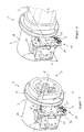
- a device 1 for locking a plug 2 in a socket 3 has as a central functional elements / assemblies the socket 3, a locking element 4, a drive unit 5 for actuating the locking element 4 and a sensor 6 for detecting at least one position of the locking element 4.
- the device 1 is arranged integrated, for example, in a charging station, wherein by means of the charging station electrical energy for electrically operable vehicles can be provided.
- the device 1 can be integrated in the vehicle which can be operated by means of electrical energy.
- the vehicle and the charging station are connected to each other via a charging cable for charging, which preferably has the plug 2 on both sides.
- the term "vehicle” refers in particular to automobiles, two-wheeled vehicles, watercraft (boats), trailers (for example, caravans, sales trailers), motorhomes and aircraft.
- the socket 3 has on a front side arranged coupling side 7 a number of Konnekttechniks instituten 8 for electrically conductive connection of the socket 3 with the plug 2.
- the socket 3 has a radially projecting from the same collar 9.
- the drive unit 5 is arranged on a side facing away from the coupling side 7 of the collar 9. The drive unit 5 is connected to a lateral surface 10 of the socket 3.
- the drive unit 5 has an electric motor with a rotating output.
- a drive axis A of the electric motor 11 is in this case oriented parallel to a longitudinal direction E of the socket 3.
- the locking element 4 is arranged.
- the locking element 4 is rotatably connected via a motor shaft 12 to the electric motor 11 and disposed between the collar 9 of the socket 3 and the drive unit 5.
- the locking element 4 is designed as a control cam 4, which has its control contour 13 along its circumference.
- the control cam 4 forms a flat disc element, which extends in a plane of action W.
- the active plane W is oriented perpendicular to the drive axis A of the electric motor 11.
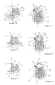
- first rotational position (release position) of the control cam 4 according to FIG. 1 it is the same with a first control contour section 14 at a first stop 15.
- second rotational position (locking position) of the control cam 4 according to FIG. 2 it is the same with a second control contour section 16 at a second stop 17.
- the first stop 15 and the second stop 17 are in this case formed on the socket 3.
- the sensor 6 In the locking position of the sensor 6 is actuated with an actuating portion 18 of the control contour 13.
- the sensor 6 is designed here as a microswitch.
- the microswitch 6 forms, together with the actuating portion 18 and a control unit, not shown, for detecting and processing a signal of the microswitch 6, a Endlagenbeéessussi 19.
- the signal of the microswitch 6 serves as an end position signal for detecting the locking position of the control cam 4th
- the control contour 13 of the control cam 4 is shaped such that the control cam 4 is radially spaced from a free end 20 of a pivot axis S rotatably held on the socket 3 latching element 21 is arranged.
- the locking element 21 slides during insertion of the plug 2 into the socket 3 along a guide slope 22 along the plug 2.
- the locking element 21 is thereby rotated from a detent position thereof clockwise about the pivot axis S, so that the free End 20 is raised with a nose 23 in the direction of the control cam 4. If the plug 2 further inserted into socket 3, the nose 23 of the locking element 21 snaps into a recess 24 of the plug 2.
- the locking element 21 takes its rest position. Usually, the rotation of the locking element 21 takes place in a clockwise direction against a torsion spring, not shown, via which the locking element 21 is held in the illustrated detent position or returned to the same, if the plug 2 is either not or fully inserted into the socket 3.
- the motor 11 To move the control cam 4 from the release position to the locked position, the motor 11 is rotated in a first rotational direction D1 (counterclockwise). Upon return of the control cam 4 from the locking position to the release position, the motor 11 is reversely rotated in a second rotational direction D2 (clockwise). If the latching element 21 is arranged in the latching position, the control cam 4 can be moved out of the release position, in which the first control contour section 14 of the same abuts against the first stop 15, into the locking position. In the locking position, the second control contour section 16 bears against the second stop 17. According to the FIGS. 5 and 6 the control contour 13 of the control cam 4 is designed such that the control cam 4 bears directly against the free end 20 of the latching element 21.
- a narrow gap may be formed whose gap height is less than a recess depth t of the recess 24. This ensures that the locking element 21 is not rotated in the locked position in a clockwise direction and the nose 23 can not be lifted out of the recess 24.
- the plug 2 is thus arranged locked in the socket 3.
- the microswitch 6 is operated in the same by means of the actuating portion 18 and the control contour 13.
- a torsion spring is arranged between the electric motor 11 and the control cam 4 as an auxiliary energy storage 25.
- the torsion spring 25 is biased upon the movement of the locking element 4 from the release position to the locking position to pressure.
- the energy stored in the torsion spring 25 (auxiliary energy, secondary energy) is dimensioned such that the control cam 4 can be returned by means of the secondary energy from the locking position to the release position.
- the electric motor 11 In the locked position, the electric motor 11 is permanently energized, so that the electric motor 11 drops the control cam 4 against the torsion spring 25 in the locking position.
- the locking element 4 In the event of a failure of the supply energy (primary energy) of the electric motor 11, the locking element 4 is returned to the release position by means of the secondary energy stored in the auxiliary energy store 25.
- a failure of the primary energy supply occurs, for example, in the event of a power failure or another defect in the charging station.
- the continuous current of the motor by means of an engine control unit, not shown, always turned off when the control cam 4 is to be returned to the release position.
- the electric motor 11 therefore rotates alone in the first rotational direction D1.
- the rotation of the control cam 4 in the second direction of rotation D2 also takes place in normal operation by means of the secondary energy stored in the auxiliary energy storage 25.
- the blocking section 26 is designed as a discontinuous blocking section 26, that is to say the control contour 13 has a jump or another point of discontinuity in the radial direction, as in the present case.
- the locking element 4 can not be rotated into the locking position.
- the microswitch 6 is not switched by means of the actuating portion 18 of the control contour 13.
- the control unit of the end position determination unit 19 recognizes that the latching element 21 is not in the latched position and that the latching element 4 is not in the latching position. Due to the missing Endlagensignals the electric motor 11 is turned off. With the charging of the vehicle is despite possibly already done electrical Konnekttechnik of plug 2 and socket 3 due to the lack of mechanical fixing of the plug 2 in the socket 3 not started.
- the electric motor 11 is initially energized such that the control cam 4 is actuated in the first rotational direction D1.
- the first control contour section 14 of the control contour 13 lifts off from the first stop 15.
- the rotation of the control cam 4 is continued until, in the locking position, the second control contour section 16 of the control contour 13 bears against the second stop 17 and the microswitch 6 is actuated by means of the actuating section 18.
- the latching element 21, whose nose 23 engages in the recess 24 of the plug 2 is located during the rotation of the control cam 4 in the locking position in the detent position.
- the control cam 4 is arranged in the locking position above the free end 20 of the locking element 21 such that the locking element 21 is not rotated clockwise about the pivot axis S and the nose 23 can not be raised in the direction of the control cam 4 from the recess 24 of the plug 2 ,
- the plug 2 is mechanically fixed in the locking position by the latching element 21 in the socket 3.
- the locking element 21 is fixed by means of the locking element 4 in its locked position.
- the torsion spring 25 arranged between the control cam 4 and the electric motor 11 is also pretensioned.
- the electric motor 11 is permanently energized, so that the locking element 4 by means of the electric motor 11 against the torsion spring 25, the control cam 4 holds in the locked position.
- the electric motor 11 is permanently energized by means of the control unit assigned to it.
- the continuous current of the motor 11 is interrupted.
- the control cam 4 is moved by means of the auxiliary energy stored in the auxiliary energy storage 25 (secondary energy) from the locked position back into the release position.
- the auxiliary energy storage 25 is thereby at least partially discharged.
- the plug 2 can be removed manually from the socket 3.
- guide bevel or other suitable guide surface may be formed on the nose 23 and the recess 24.
- the latching element 21 does not engage with its nose 23 or not completely into the recess 24 of the plug 2.
- the locking element 21 is thereby not positioned in its locked position.
- the control cam 4 is moved from the release position into the locking position, the blocking section 26 of the control contour 13 strikes against the free end 20 of the latching element 21.
- the latching element 21 blocks the further rotary movement of the control cam 4. Since the locking element 4 is not rotated to the locking position, the microswitch 6 is not actuated by means of the actuating portion 18. Consequently, no limit signal is generated and sent to the control unit of the end position determination unit 19 forwarded.
- an electromagnet may be arranged as adjusting means 11, for example, an electromagnet.
- the electromagnet 11 may be associated with a locking element 4 actuated by it for locking the latching element 21. It is also possible that the electromagnet 11 itself serves as a locking element 4 and the locking element 21 is locked or released.
- not shown embodiment of the invention can be dispensed with the arrangement of stops 15, 17.
- the locking element 4, one or more sensors 6 are assigned such that can be closed by means of the sensor signals on the positioning of the locking element 4 in the release position and / or in the locking position and / or in the intermediate position.
- the electric motor 11 can be actuated either in one or in two directions of rotation. If the electric motor 11 is actuated solely in one direction of rotation, the auxiliary energy store 25 is preferably formed as a capacitor and / or accumulator for storing electrical secondary energy.
- the locking element 4 and / or the locking element 21 may in this case be designed such that helbsthemmung occurs between them in the release position and / or in the locked position. The electric motor 11 then does not have to be permanently energized for positioning the locking element 4 in the release position and / or the locking position.
- a variety of different sensors such as a reed contact, a Hall sensor or an optical sensor can be used.
- the sensor 6 may be associated with the latching element 21 and / or the locking element 4 and / or both. For example, it can be detected by means of an optical sensor, whether the locking element 21 in the locking position and at the same time the locking element 4 are positioned in the locking position.
- the end position determination unit 19 can be executed without a sensor.
- the end position signal can be determined, for example, by means of so-called ripple counting.
- ripple counting based on operating parameters of a DC motor 11 (in particular motor current and motor voltage), the rotational speed and the position of the DC motor 11 can be detected and controlled sensorless.
- a device 1 is realized with an end position determination unit 19, which in the case of Waste of the primary supply energy not unlocked by means of the auxiliary energy storage 25 to release the plug 2 in the socket 3.
- Such a device 1 may be arranged for example in the vehicle.
- a failure of the primary energy equals here a completely discharged vehicle memory.
- the vehicle can not be operated, so that can be dispensed with the unlocking of the plug 2 in the socket 3.
- the device 1 can otherwise be realized identically to the illustrated embodiment of the invention.
- the arrangement of the end position determination unit 19 can be dispensed with.
- control unit of the actuating means 11 and / or the control unit of the end position determination unit 19 can be embodied as separate assemblies, as separate functional modules in a common assembly or functionally or spatially integrated. They can also be part of further control components of the charging station or of the vehicle.
- the socket 3 of the charging station can also be designed as a plug and the plug 2 of the charging cable as a socket.
- socket and plug each form a plug-in element of a plug-in device electrical connection.
- the charging station can be designed as a charging station.
- the charging station can be arranged spatially distributed, for example, the socket 3 can be provided spatially separated from the control unit. On a columnar geometry of a housing of the charging station is not important.
Landscapes
- Engineering & Computer Science (AREA)
- Computer Security & Cryptography (AREA)
- Power Engineering (AREA)
- Transportation (AREA)
- Mechanical Engineering (AREA)
- Details Of Connecting Devices For Male And Female Coupling (AREA)
- Electric Propulsion And Braking For Vehicles (AREA)
Applications Claiming Priority (1)
| Application Number | Priority Date | Filing Date | Title |
|---|---|---|---|
| DE102009039652A DE102009039652A1 (de) | 2009-09-02 | 2009-09-02 | Vorrichtung und Verfahren zur Verriegelung eines Steckers in einer Steckdose |
Publications (3)
| Publication Number | Publication Date |
|---|---|
| EP2293392A2 true EP2293392A2 (fr) | 2011-03-09 |
| EP2293392A3 EP2293392A3 (fr) | 2014-06-04 |
| EP2293392B1 EP2293392B1 (fr) | 2016-10-26 |
Family
ID=43128219
Family Applications (2)
| Application Number | Title | Priority Date | Filing Date |
|---|---|---|---|
| EP10173524.9A Active EP2293391B1 (fr) | 2009-09-02 | 2010-08-20 | Dispositif et procédé de verrouillage d'un connecteur dans une prise |
| EP10173528.0A Active EP2293392B1 (fr) | 2009-09-02 | 2010-08-20 | Dispositif et procédé de verrouillage d'un connecteur dans une prise |
Family Applications Before (1)
| Application Number | Title | Priority Date | Filing Date |
|---|---|---|---|
| EP10173524.9A Active EP2293391B1 (fr) | 2009-09-02 | 2010-08-20 | Dispositif et procédé de verrouillage d'un connecteur dans une prise |
Country Status (2)
| Country | Link |
|---|---|
| EP (2) | EP2293391B1 (fr) |
| DE (1) | DE102009039652A1 (fr) |
Cited By (2)
| Publication number | Priority date | Publication date | Assignee | Title |
|---|---|---|---|---|
| CN104756328A (zh) * | 2012-10-22 | 2015-07-01 | 古河电气工业株式会社 | 供电连接器 |
| WO2018192624A1 (fr) * | 2017-04-21 | 2018-10-25 | Harting Electric Gmbh & Co. Kg | Dispositif formant boîtier de montage et procédé de déverrouillage |
Families Citing this family (33)
| Publication number | Priority date | Publication date | Assignee | Title |
|---|---|---|---|---|
| DE102010042592A1 (de) * | 2010-10-18 | 2012-04-19 | Elektro-Bauelemente Gmbh | Vorrichtung und Verfahren zum Bereitstellen elektrischer Energie für elektrisch betreibbare Fahrzeuge |
| DE102011016481B4 (de) | 2011-04-08 | 2015-05-13 | Temtec Fahrzeugtechnik Entwicklungsgesellschaft Mbh | Verriegelungssystem für eine an einem Kraftfahrzeug, einer Ladestation oder einer Wand angeordnete Steckkuppeleinrichtung und Steckkuppeleinrichtung |
| DE102011050536A1 (de) | 2011-05-20 | 2012-11-22 | Phoenix Contact Gmbh & Co. Kg | Steckverbinder |
| CN102815188B (zh) * | 2011-06-03 | 2016-03-02 | 许继电源有限公司 | 一种用于电池箱的撞击式自锁紧机构 |
| DE102011050938A1 (de) * | 2011-06-08 | 2012-12-13 | Phoenix Contact Gmbh & Co. Kg | Kabelstecker |
| DE102011083819B4 (de) | 2011-09-30 | 2024-09-26 | Kiekert Aktiengesellschaft | Verriegelungseinrichtung für ein Kraftfahrzeug |
| DE102011086673B4 (de) * | 2011-11-18 | 2023-12-21 | Kiekert Aktiengesellschaft | Ladestecker mit Verriegelungserkennung nebst Verfahren |
| DE102011122629B4 (de) * | 2011-12-22 | 2017-08-03 | Phoenix Contact Gmbh & Co. Kg | Entriegelungsschaltung |
| US20130337669A1 (en) * | 2012-06-13 | 2013-12-19 | Schneider Electric USA, Inc. | Locking device for electric vehicle charging connector |
| EP2871723B1 (fr) * | 2012-07-05 | 2018-04-25 | Nissan Motor Co., Ltd | Dispositif de port de charge destiné à un véhicule électrique |
| DE102012022413B3 (de) * | 2012-11-15 | 2014-02-27 | Temtec Fahrzeugtechnik Entwicklungsgesellschaft Mbh | Verriegelungsvorrichtung zum Verriegeln eines elektrischen Steckers in einer Buchse |
| DE102013102823A1 (de) * | 2013-03-19 | 2014-09-25 | Phoenix Contact Gmbh & Co. Kg | Ladestecker mit Verstärkungselement |
| DE102016105975A1 (de) | 2016-04-01 | 2017-10-05 | Harting Ag & Co. Kg | Verriegelungsvorrichtung für Steckverbinder |
| EP3252879B1 (fr) * | 2016-05-31 | 2020-08-26 | TE Connectivity Germany GmbH | Module actionneur conçu pour charger des entrées |
| DE102017207720A1 (de) * | 2017-05-08 | 2018-11-08 | Bayerische Motoren Werke Aktiengesellschaft | Entsichern einer Ladekabelverriegelung mittels Transponder |
| CN109149262B (zh) * | 2017-06-28 | 2021-05-18 | 中航光电科技股份有限公司 | 电动车辆及其充电插座、充电插座使用的电子锁 |
| DE102017118751B4 (de) * | 2017-08-17 | 2019-06-06 | Harting Electric Gmbh & Co. Kg | Verriegelungsvorrichtung mit Nockenwelle für eine Steckverbindung |
| DE102017123207A1 (de) * | 2017-10-06 | 2019-04-11 | Kiekert Ag | Elektrische Anschlussvorrichtung |
| CN109050279A (zh) * | 2017-12-30 | 2018-12-21 | 广州大正新材料科技有限公司 | 一种自动定位的悬挂式充电枪装置及充电方法 |
| CN109774512A (zh) * | 2018-03-21 | 2019-05-21 | 郑州赫恩电子信息技术有限公司 | 用于新能源汽车快充接口的锁紧机构 |
| CN109904678B (zh) * | 2018-03-21 | 2020-10-27 | 广州趣科信息科技有限公司 | 用于新能源汽车充电接口的斜接式触发机构 |
| DE102018109661A1 (de) * | 2018-04-23 | 2019-10-24 | Kiekert Ag | Verriegelungseinrichtung |
| DE102018109660A1 (de) * | 2018-04-23 | 2019-10-24 | Kiekert Ag | Verriegelungseinrichtung |
| DE102018111593A1 (de) * | 2018-05-15 | 2019-11-21 | Volkswagen Aktiengesellschaft | Ladestation zur Abgabe von Energie an Elektrofahrzeuge, insbesondere auch an Hybrid-Fahrzeuge bzw. Verfahren zum Betrieb einer Ladestation zur Abgabe von Energie an Elektrofahrzeuge, insbesondere auch an Hybrid-Fahrzeuge |
| DE102018129671A1 (de) * | 2018-11-26 | 2020-05-28 | Kiekert Aktiengesellschaft | Verriegelungsvorrichtung für eine elektrische Ladevorrichtung eines Kraftfahrzeuges |
| DE102018131610A1 (de) * | 2018-12-10 | 2020-06-10 | Phoenix Contact E-Mobility Gmbh | Ladestecker mit einer Rastverbindungsdetektion |
| DE102019117465A1 (de) * | 2019-04-03 | 2020-10-08 | Kiekert Aktiengesellschaft | Verriegelungsvorrichtung für eine elektrische Ladevorrichtung |
| CN110254265A (zh) * | 2019-07-25 | 2019-09-20 | 北京大智伟业科技有限公司 | 一种立体车库充电电源自动插接装置 |
| DE102020132027A1 (de) | 2020-12-02 | 2022-06-02 | Kiekert Aktiengesellschaft | Elektromotorische Antriebseinheit für kraftfahrzeug-technische Anwendungen |
| DE102021128024B3 (de) * | 2021-10-27 | 2022-12-08 | Md Elektronik Gmbh | Elektrische steckverbindung mit selbstverriegelungsfunktion |
| CN114520438A (zh) * | 2022-02-23 | 2022-05-20 | 深圳中科捷飞科技有限公司 | 一种充电装置及控制方法 |
| CN115626073A (zh) * | 2022-10-26 | 2023-01-20 | 厦门亚锝电子科技有限公司 | 一种充电桩 |
| CN116885500B (zh) * | 2023-08-29 | 2024-04-19 | 江苏健龙电器有限公司 | 一种船载电池舱自动定位锁止装置、充电装置及锁止方法 |
Family Cites Families (13)
| Publication number | Priority date | Publication date | Assignee | Title |
|---|---|---|---|---|
| DE2843247A1 (de) * | 1978-10-04 | 1980-04-17 | Dornier Gmbh | Elektrische steckvorrichtung |
| JP2978348B2 (ja) * | 1992-12-18 | 1999-11-15 | 矢崎総業株式会社 | 給電コネクタ |
| US5413493A (en) * | 1993-01-15 | 1995-05-09 | Hubbell Incorporated | Electrical connector assembly, especially for electric vehicle |
| US5433623A (en) * | 1993-04-19 | 1995-07-18 | Sumitomo Wiring Systems, Ltd. | Coupling device of charging connector assembly for electric car |
| JP2916348B2 (ja) * | 1993-07-22 | 1999-07-05 | 住友電装株式会社 | 電気自動車充電用コネクタ |
| JP2752032B2 (ja) * | 1993-09-20 | 1998-05-18 | 矢崎総業株式会社 | 給電コネクタ |
| DE19544942C2 (de) * | 1994-12-01 | 2001-12-06 | Yazaki Corp | Verbindungsvorrichtung mit einem Spannungszufuhrsteckverbinder und einem Spannungsaufnahmesteckverbinder und Verfahren zum Verbinden/Trennen einer Spannungszufuhreinrichtung |
| EP0887891A1 (fr) * | 1995-08-09 | 1998-12-30 | Sumitomo Wiring Systems, Ltd. | Dispositif de verrouillage pour connecteurs et son utilisation pour charger des connecteurs et/ou des connecteurs à haute tension |
| JPH10144392A (ja) * | 1996-11-14 | 1998-05-29 | Sumitomo Wiring Syst Ltd | 電気自動車のチャージ用コネクタ |
| US20020064983A1 (en) * | 2000-06-13 | 2002-05-30 | Patey Kenneth C. | Apparatus and method for remotely unplugging electrical plugs |
| DE10102242A1 (de) * | 2001-01-19 | 2002-07-25 | Xcellsis Gmbh | Mobile Vorrichtung mit einer Einrichtung zur Erzeugung elektricher Energie und mit elektrischen Verbrauchern, die in einem mit der Einrichtung zur Erzeugung elektrischer Energie verbundenen Energieverteilungsnetz angeordnet sind |
| DE10261016A1 (de) * | 2002-12-24 | 2004-07-08 | Robert Bosch Gmbh | Steckkontrolle zur Detektion einer korrekt ausgeführten elektrischen Steckverbindung |
| DE102007002025A1 (de) * | 2007-01-13 | 2008-07-17 | Daimler Ag | Fahrzeug |
-
2009
- 2009-09-02 DE DE102009039652A patent/DE102009039652A1/de not_active Ceased
-
2010
- 2010-08-20 EP EP10173524.9A patent/EP2293391B1/fr active Active
- 2010-08-20 EP EP10173528.0A patent/EP2293392B1/fr active Active
Non-Patent Citations (1)
| Title |
|---|
| None |
Cited By (6)
| Publication number | Priority date | Publication date | Assignee | Title |
|---|---|---|---|---|
| CN104756328A (zh) * | 2012-10-22 | 2015-07-01 | 古河电气工业株式会社 | 供电连接器 |
| WO2018192624A1 (fr) * | 2017-04-21 | 2018-10-25 | Harting Electric Gmbh & Co. Kg | Dispositif formant boîtier de montage et procédé de déverrouillage |
| KR20190140459A (ko) * | 2017-04-21 | 2019-12-19 | 하르팅 에렉트릭 게엠베하 운트 코우. 카게 | 부착 하우징 장치 및 잠금 해제 방법 |
| CN110770980A (zh) * | 2017-04-21 | 2020-02-07 | 哈廷电子有限公司及两合公司 | 安装外壳组件和用于解锁的方法 |
| CN110770980B (zh) * | 2017-04-21 | 2021-07-16 | 哈廷电子有限公司及两合公司 | 安装外壳组件和用于解锁的方法 |
| EP3613109B1 (fr) * | 2017-04-21 | 2021-11-10 | HARTING Electric GmbH & Co. KG | Dispositif formant boîtier de montage et procédé de déverrouillage |
Also Published As
| Publication number | Publication date |
|---|---|
| EP2293391A2 (fr) | 2011-03-09 |
| DE102009039652A1 (de) | 2011-03-17 |
| EP2293391A3 (fr) | 2014-06-04 |
| EP2293391B1 (fr) | 2016-10-26 |
| EP2293392B1 (fr) | 2016-10-26 |
| EP2293392A3 (fr) | 2014-06-04 |
Similar Documents
| Publication | Publication Date | Title |
|---|---|---|
| EP2293392B1 (fr) | Dispositif et procédé de verrouillage d'un connecteur dans une prise | |
| EP2648935B1 (fr) | Dispositif de charge avec détection de verrouillage | |
| DE102010038570B4 (de) | Ladeeinrichtung für ein Elektrfahrzeug und Verfahren | |
| DE102012106076A1 (de) | Elektrisch betätigte Lenkradschloßeinrichtung | |
| DE102013112991A1 (de) | Ladestecker zum Laden eines Elektrofahrzeugs | |
| DE19821899C2 (de) | Drehschalter, insbesondere Zündanlaßschalter | |
| EP3543439B1 (fr) | Procédé pour un ensemble serrure | |
| DE102013105429B4 (de) | Elektrische Lenkradschlosseinrichtung | |
| EP1634729B2 (fr) | Commande d'entraînement d'un attelage de remorque | |
| EP3039211B1 (fr) | Serrure électrique de véhicule automobile présentant un accumulateur à ressort | |
| DE102010038568A1 (de) | Elektrische Steckverbindung | |
| EP3909805A1 (fr) | Dispositif, en particulier station de charge ou véhicule électrique, et module pour un tel dispositif | |
| EP3755584B1 (fr) | Système de retenue de passagers dans un véhicule automoteur | |
| DE202013006616U1 (de) | Vorrichtung zur mechanischen Verriegelung eines Ladesteckers in einer Ladedose | |
| DE102011086648B4 (de) | Elektrisch betätigte Lenkradschlosseinrichtung | |
| WO2013071906A2 (fr) | Dispositif de verrouillage d'un connecteur électrique d'un véhicule automobile | |
| DE102017110123B4 (de) | Steckverbinder, Leitungssatz und Herstellverfahren für sicherheitsrelevante Steckverbindungen | |
| WO2011042220A1 (fr) | Dispositif de déverrouillage | |
| DE102023102492A1 (de) | Steueranordnung für ein Kraftfahrzeugschloss | |
| DE102013113317A1 (de) | Elektrisch betätigte Lenkschloßeinrichtung | |
| WO2013071913A2 (fr) | Connecteur de recharge à verrouillage identifiable et procédé associé | |
| DE4498428B4 (de) | Diebstahlsicherung für Kraftfahrzeuge mit Getriebe oder derartiges Getriebe | |
| DE102008053777A1 (de) | Tankverschlussanordnung | |
| DE102022132316A1 (de) | E-Bike mit Elektroschloss für den Akku | |
| DE102014004647A1 (de) | Lenkradschloss mit Motorantrieb |
Legal Events
| Date | Code | Title | Description |
|---|---|---|---|
| PUAI | Public reference made under article 153(3) epc to a published international application that has entered the european phase |
Free format text: ORIGINAL CODE: 0009012 |
|
| AK | Designated contracting states |
Kind code of ref document: A2 Designated state(s): AL AT BE BG CH CY CZ DE DK EE ES FI FR GB GR HR HU IE IS IT LI LT LU LV MC MK MT NL NO PL PT RO SE SI SK SM TR |
|
| AX | Request for extension of the european patent |
Extension state: BA ME RS |
|
| PUAL | Search report despatched |
Free format text: ORIGINAL CODE: 0009013 |
|
| AK | Designated contracting states |
Kind code of ref document: A3 Designated state(s): AL AT BE BG CH CY CZ DE DK EE ES FI FR GB GR HR HU IE IS IT LI LT LU LV MC MK MT NL NO PL PT RO SE SI SK SM TR |
|
| AX | Request for extension of the european patent |
Extension state: BA ME RS |
|
| RIC1 | Information provided on ipc code assigned before grant |
Ipc: H01R 13/639 20060101ALI20140428BHEP Ipc: H01R 13/641 20060101AFI20140428BHEP Ipc: B60L 11/18 20060101ALI20140428BHEP Ipc: H01R 13/70 20060101ALI20140428BHEP |
|
| 17P | Request for examination filed |
Effective date: 20141126 |
|
| RBV | Designated contracting states (corrected) |
Designated state(s): AL AT BE BG CH CY CZ DE DK EE ES FI FR GB GR HR HU IE IS IT LI LT LU LV MC MK MT NL NO PL PT RO SE SI SK SM TR |
|
| GRAP | Despatch of communication of intention to grant a patent |
Free format text: ORIGINAL CODE: EPIDOSNIGR1 |
|
| INTG | Intention to grant announced |
Effective date: 20160609 |
|
| GRAS | Grant fee paid |
Free format text: ORIGINAL CODE: EPIDOSNIGR3 |
|
| GRAA | (expected) grant |
Free format text: ORIGINAL CODE: 0009210 |
|
| AK | Designated contracting states |
Kind code of ref document: B1 Designated state(s): AL AT BE BG CH CY CZ DE DK EE ES FI FR GB GR HR HU IE IS IT LI LT LU LV MC MK MT NL NO PL PT RO SE SI SK SM TR |
|
| REG | Reference to a national code |
Ref country code: GB Ref legal event code: FG4D Free format text: NOT ENGLISH |
|
| REG | Reference to a national code |
Ref country code: CH Ref legal event code: EP |
|
| REG | Reference to a national code |
Ref country code: AT Ref legal event code: REF Ref document number: 840627 Country of ref document: AT Kind code of ref document: T Effective date: 20161115 |
|
| REG | Reference to a national code |
Ref country code: IE Ref legal event code: FG4D Free format text: LANGUAGE OF EP DOCUMENT: GERMAN |
|
| REG | Reference to a national code |
Ref country code: DE Ref legal event code: R096 Ref document number: 502010012617 Country of ref document: DE |
|
| REG | Reference to a national code |
Ref country code: NL Ref legal event code: FP |
|
| REG | Reference to a national code |
Ref country code: LT Ref legal event code: MG4D |
|
| PG25 | Lapsed in a contracting state [announced via postgrant information from national office to epo] |
Ref country code: LV Free format text: LAPSE BECAUSE OF FAILURE TO SUBMIT A TRANSLATION OF THE DESCRIPTION OR TO PAY THE FEE WITHIN THE PRESCRIBED TIME-LIMIT Effective date: 20161026 |
|
| PG25 | Lapsed in a contracting state [announced via postgrant information from national office to epo] |
Ref country code: SE Free format text: LAPSE BECAUSE OF FAILURE TO SUBMIT A TRANSLATION OF THE DESCRIPTION OR TO PAY THE FEE WITHIN THE PRESCRIBED TIME-LIMIT Effective date: 20161026 Ref country code: NO Free format text: LAPSE BECAUSE OF FAILURE TO SUBMIT A TRANSLATION OF THE DESCRIPTION OR TO PAY THE FEE WITHIN THE PRESCRIBED TIME-LIMIT Effective date: 20170126 Ref country code: LT Free format text: LAPSE BECAUSE OF FAILURE TO SUBMIT A TRANSLATION OF THE DESCRIPTION OR TO PAY THE FEE WITHIN THE PRESCRIBED TIME-LIMIT Effective date: 20161026 Ref country code: GR Free format text: LAPSE BECAUSE OF FAILURE TO SUBMIT A TRANSLATION OF THE DESCRIPTION OR TO PAY THE FEE WITHIN THE PRESCRIBED TIME-LIMIT Effective date: 20170127 |
|
| PG25 | Lapsed in a contracting state [announced via postgrant information from national office to epo] |
Ref country code: ES Free format text: LAPSE BECAUSE OF FAILURE TO SUBMIT A TRANSLATION OF THE DESCRIPTION OR TO PAY THE FEE WITHIN THE PRESCRIBED TIME-LIMIT Effective date: 20161026 Ref country code: FI Free format text: LAPSE BECAUSE OF FAILURE TO SUBMIT A TRANSLATION OF THE DESCRIPTION OR TO PAY THE FEE WITHIN THE PRESCRIBED TIME-LIMIT Effective date: 20161026 Ref country code: PT Free format text: LAPSE BECAUSE OF FAILURE TO SUBMIT A TRANSLATION OF THE DESCRIPTION OR TO PAY THE FEE WITHIN THE PRESCRIBED TIME-LIMIT Effective date: 20170227 Ref country code: HR Free format text: LAPSE BECAUSE OF FAILURE TO SUBMIT A TRANSLATION OF THE DESCRIPTION OR TO PAY THE FEE WITHIN THE PRESCRIBED TIME-LIMIT Effective date: 20161026 Ref country code: PL Free format text: LAPSE BECAUSE OF FAILURE TO SUBMIT A TRANSLATION OF THE DESCRIPTION OR TO PAY THE FEE WITHIN THE PRESCRIBED TIME-LIMIT Effective date: 20161026 Ref country code: IS Free format text: LAPSE BECAUSE OF FAILURE TO SUBMIT A TRANSLATION OF THE DESCRIPTION OR TO PAY THE FEE WITHIN THE PRESCRIBED TIME-LIMIT Effective date: 20170226 |
|
| REG | Reference to a national code |
Ref country code: DE Ref legal event code: R097 Ref document number: 502010012617 Country of ref document: DE |
|
| PG25 | Lapsed in a contracting state [announced via postgrant information from national office to epo] |
Ref country code: DK Free format text: LAPSE BECAUSE OF FAILURE TO SUBMIT A TRANSLATION OF THE DESCRIPTION OR TO PAY THE FEE WITHIN THE PRESCRIBED TIME-LIMIT Effective date: 20161026 Ref country code: SK Free format text: LAPSE BECAUSE OF FAILURE TO SUBMIT A TRANSLATION OF THE DESCRIPTION OR TO PAY THE FEE WITHIN THE PRESCRIBED TIME-LIMIT Effective date: 20161026 Ref country code: CZ Free format text: LAPSE BECAUSE OF FAILURE TO SUBMIT A TRANSLATION OF THE DESCRIPTION OR TO PAY THE FEE WITHIN THE PRESCRIBED TIME-LIMIT Effective date: 20161026 Ref country code: EE Free format text: LAPSE BECAUSE OF FAILURE TO SUBMIT A TRANSLATION OF THE DESCRIPTION OR TO PAY THE FEE WITHIN THE PRESCRIBED TIME-LIMIT Effective date: 20161026 Ref country code: RO Free format text: LAPSE BECAUSE OF FAILURE TO SUBMIT A TRANSLATION OF THE DESCRIPTION OR TO PAY THE FEE WITHIN THE PRESCRIBED TIME-LIMIT Effective date: 20161026 |
|
| REG | Reference to a national code |
Ref country code: FR Ref legal event code: PLFP Year of fee payment: 8 |
|
| PG25 | Lapsed in a contracting state [announced via postgrant information from national office to epo] |
Ref country code: SM Free format text: LAPSE BECAUSE OF FAILURE TO SUBMIT A TRANSLATION OF THE DESCRIPTION OR TO PAY THE FEE WITHIN THE PRESCRIBED TIME-LIMIT Effective date: 20161026 Ref country code: BG Free format text: LAPSE BECAUSE OF FAILURE TO SUBMIT A TRANSLATION OF THE DESCRIPTION OR TO PAY THE FEE WITHIN THE PRESCRIBED TIME-LIMIT Effective date: 20170126 Ref country code: IT Free format text: LAPSE BECAUSE OF FAILURE TO SUBMIT A TRANSLATION OF THE DESCRIPTION OR TO PAY THE FEE WITHIN THE PRESCRIBED TIME-LIMIT Effective date: 20161026 |
|
| PLBE | No opposition filed within time limit |
Free format text: ORIGINAL CODE: 0009261 |
|
| STAA | Information on the status of an ep patent application or granted ep patent |
Free format text: STATUS: NO OPPOSITION FILED WITHIN TIME LIMIT |
|
| 26N | No opposition filed |
Effective date: 20170727 |
|
| PG25 | Lapsed in a contracting state [announced via postgrant information from national office to epo] |
Ref country code: SI Free format text: LAPSE BECAUSE OF FAILURE TO SUBMIT A TRANSLATION OF THE DESCRIPTION OR TO PAY THE FEE WITHIN THE PRESCRIBED TIME-LIMIT Effective date: 20161026 |
|
| REG | Reference to a national code |
Ref country code: CH Ref legal event code: PL |
|
| PG25 | Lapsed in a contracting state [announced via postgrant information from national office to epo] |
Ref country code: MC Free format text: LAPSE BECAUSE OF FAILURE TO SUBMIT A TRANSLATION OF THE DESCRIPTION OR TO PAY THE FEE WITHIN THE PRESCRIBED TIME-LIMIT Effective date: 20161026 |
|
| PG25 | Lapsed in a contracting state [announced via postgrant information from national office to epo] |
Ref country code: LI Free format text: LAPSE BECAUSE OF NON-PAYMENT OF DUE FEES Effective date: 20170831 Ref country code: CH Free format text: LAPSE BECAUSE OF NON-PAYMENT OF DUE FEES Effective date: 20170831 |
|
| REG | Reference to a national code |
Ref country code: IE Ref legal event code: MM4A |
|
| REG | Reference to a national code |
Ref country code: BE Ref legal event code: MM Effective date: 20170831 |
|
| PG25 | Lapsed in a contracting state [announced via postgrant information from national office to epo] |
Ref country code: LU Free format text: LAPSE BECAUSE OF NON-PAYMENT OF DUE FEES Effective date: 20170820 |
|
| PG25 | Lapsed in a contracting state [announced via postgrant information from national office to epo] |
Ref country code: IE Free format text: LAPSE BECAUSE OF NON-PAYMENT OF DUE FEES Effective date: 20170820 |
|
| REG | Reference to a national code |
Ref country code: FR Ref legal event code: PLFP Year of fee payment: 9 |
|
| PG25 | Lapsed in a contracting state [announced via postgrant information from national office to epo] |
Ref country code: BE Free format text: LAPSE BECAUSE OF NON-PAYMENT OF DUE FEES Effective date: 20170831 |
|
| PG25 | Lapsed in a contracting state [announced via postgrant information from national office to epo] |
Ref country code: MT Free format text: LAPSE BECAUSE OF FAILURE TO SUBMIT A TRANSLATION OF THE DESCRIPTION OR TO PAY THE FEE WITHIN THE PRESCRIBED TIME-LIMIT Effective date: 20161026 |
|
| PG25 | Lapsed in a contracting state [announced via postgrant information from national office to epo] |
Ref country code: HU Free format text: LAPSE BECAUSE OF FAILURE TO SUBMIT A TRANSLATION OF THE DESCRIPTION OR TO PAY THE FEE WITHIN THE PRESCRIBED TIME-LIMIT; INVALID AB INITIO Effective date: 20100820 |
|
| PG25 | Lapsed in a contracting state [announced via postgrant information from national office to epo] |
Ref country code: CY Free format text: LAPSE BECAUSE OF NON-PAYMENT OF DUE FEES Effective date: 20161026 |
|
| PG25 | Lapsed in a contracting state [announced via postgrant information from national office to epo] |
Ref country code: MK Free format text: LAPSE BECAUSE OF FAILURE TO SUBMIT A TRANSLATION OF THE DESCRIPTION OR TO PAY THE FEE WITHIN THE PRESCRIBED TIME-LIMIT Effective date: 20161026 |
|
| PG25 | Lapsed in a contracting state [announced via postgrant information from national office to epo] |
Ref country code: TR Free format text: LAPSE BECAUSE OF FAILURE TO SUBMIT A TRANSLATION OF THE DESCRIPTION OR TO PAY THE FEE WITHIN THE PRESCRIBED TIME-LIMIT Effective date: 20161026 |
|
| REG | Reference to a national code |
Ref country code: DE Ref legal event code: R082 Ref document number: 502010012617 Country of ref document: DE Representative=s name: TARVENKORN & WICKORD PATENTANWAELTE PARTNERSCH, DE Ref country code: DE Ref legal event code: R081 Ref document number: 502010012617 Country of ref document: DE Owner name: COMPLEO CHARGING SOLUTIONS AG, DE Free format text: FORMER OWNER: ELEKTRO-BAUELEMENTE GMBH, 44536 LUENEN, DE Ref country code: DE Ref legal event code: R081 Ref document number: 502010012617 Country of ref document: DE Owner name: COMPLEO CHARGING SOLUTIONS GMBH, DE Free format text: FORMER OWNER: ELEKTRO-BAUELEMENTE GMBH, 44536 LUENEN, DE Ref country code: DE Ref legal event code: R081 Ref document number: 502010012617 Country of ref document: DE Owner name: COMPLEO CHARGING SOLUTIONS GMBH & CO. KG, DE Free format text: FORMER OWNER: ELEKTRO-BAUELEMENTE GMBH, 44536 LUENEN, DE |
|
| PG25 | Lapsed in a contracting state [announced via postgrant information from national office to epo] |
Ref country code: AL Free format text: LAPSE BECAUSE OF FAILURE TO SUBMIT A TRANSLATION OF THE DESCRIPTION OR TO PAY THE FEE WITHIN THE PRESCRIBED TIME-LIMIT Effective date: 20161026 |
|
| REG | Reference to a national code |
Ref country code: NL Ref legal event code: PD Owner name: COMPLEO CHARGING SOLUTIONS GMBH; DE Free format text: DETAILS ASSIGNMENT: CHANGE OF OWNER(S), ASSIGNMENT; FORMER OWNER NAME: ELEKTRO-BAUELEMENTE GMBH Effective date: 20200710 |
|
| REG | Reference to a national code |
Ref country code: GB Ref legal event code: 732E Free format text: REGISTERED BETWEEN 20201008 AND 20201014 |
|
| REG | Reference to a national code |
Ref country code: DE Ref legal event code: R082 Ref document number: 502010012617 Country of ref document: DE Representative=s name: TARVENKORN & WICKORD PATENTANWAELTE PARTNERSCH, DE Ref country code: DE Ref legal event code: R081 Ref document number: 502010012617 Country of ref document: DE Owner name: COMPLEO CHARGING SOLUTIONS AG, DE Free format text: FORMER OWNER: COMPLEO CHARGING SOLUTIONS GMBH, 44536 LUENEN, DE Ref country code: DE Ref legal event code: R081 Ref document number: 502010012617 Country of ref document: DE Owner name: COMPLEO CHARGING SOLUTIONS GMBH & CO. KG, DE Free format text: FORMER OWNER: COMPLEO CHARGING SOLUTIONS GMBH, 44536 LUENEN, DE |
|
| REG | Reference to a national code |
Ref country code: AT Ref legal event code: PC Ref document number: 840627 Country of ref document: AT Kind code of ref document: T Owner name: COMPLEO CHARGING SOLUTIONS GMBH, DE Effective date: 20200921 |
|
| REG | Reference to a national code |
Ref country code: NL Ref legal event code: PD Owner name: COMPLEO CHARGING SOLUTIONS AG; DE Free format text: DETAILS ASSIGNMENT: CHANGE OF OWNER(S), CHANGE OF LEGAL ENTITY; FORMER OWNER NAME: ELEKTRO-BAUELEMENTE GMBH Effective date: 20201119 |
|
| REG | Reference to a national code |
Ref country code: AT Ref legal event code: HC Ref document number: 840627 Country of ref document: AT Kind code of ref document: T Owner name: COMPLEO CHARGING SOLUTIONS AG, DE Effective date: 20210217 |
|
| REG | Reference to a national code |
Ref country code: DE Ref legal event code: R082 Ref document number: 502010012617 Country of ref document: DE Representative=s name: WICKORD BUSER PATENTANWAELTE PARTG MBB, DE |
|
| REG | Reference to a national code |
Ref country code: DE Ref legal event code: R081 Ref document number: 502010012617 Country of ref document: DE Owner name: COMPLEO CHARGING SOLUTIONS GMBH & CO. KG, DE Free format text: FORMER OWNER: COMPLEO CHARGING SOLUTIONS AG, 44309 DORTMUND, DE |
|
| REG | Reference to a national code |
Ref country code: DE Ref legal event code: R082 Ref document number: 502010012617 Country of ref document: DE |
|
| PGFP | Annual fee paid to national office [announced via postgrant information from national office to epo] |
Ref country code: NL Payment date: 20250821 Year of fee payment: 16 |
|
| PGFP | Annual fee paid to national office [announced via postgrant information from national office to epo] |
Ref country code: DE Payment date: 20250820 Year of fee payment: 16 |
|
| PGFP | Annual fee paid to national office [announced via postgrant information from national office to epo] |
Ref country code: GB Payment date: 20250828 Year of fee payment: 16 |
|
| PGFP | Annual fee paid to national office [announced via postgrant information from national office to epo] |
Ref country code: AT Payment date: 20250821 Year of fee payment: 16 Ref country code: FR Payment date: 20250828 Year of fee payment: 16 |