EP2293409B1 - Unité d'îlot d'un réseau d'énergie en îlot pour la communication de demandes d'énergie avec une autre unité d'îlot - Google Patents
Unité d'îlot d'un réseau d'énergie en îlot pour la communication de demandes d'énergie avec une autre unité d'îlot Download PDFInfo
- Publication number
- EP2293409B1 EP2293409B1 EP10175111.3A EP10175111A EP2293409B1 EP 2293409 B1 EP2293409 B1 EP 2293409B1 EP 10175111 A EP10175111 A EP 10175111A EP 2293409 B1 EP2293409 B1 EP 2293409B1
- Authority
- EP
- European Patent Office
- Prior art keywords
- unit
- energy
- island
- isolated
- isolated unit
- Prior art date
- Legal status (The legal status is an assumption and is not a legal conclusion. Google has not performed a legal analysis and makes no representation as to the accuracy of the status listed.)
- Active
Links
Images


Classifications
-
- H—ELECTRICITY
- H02—GENERATION; CONVERSION OR DISTRIBUTION OF ELECTRIC POWER
- H02J—ELECTRIC POWER NETWORKS; CIRCUIT ARRANGEMENTS OR SYSTEMS FOR SUPPLYING OR DISTRIBUTING ELECTRIC POWER; SYSTEMS FOR STORING ELECTRIC ENERGY
- H02J3/00—Circuit arrangements for AC mains or AC distribution networks
- H02J3/38—Arrangements for feeding a single network from two or more generators or sources in parallel; Arrangements for feeding already energised networks from additional generators or sources in parallel
- H02J3/381—Dispersed generators
-
- H—ELECTRICITY
- H02—GENERATION; CONVERSION OR DISTRIBUTION OF ELECTRIC POWER
- H02J—ELECTRIC POWER NETWORKS; CIRCUIT ARRANGEMENTS OR SYSTEMS FOR SUPPLYING OR DISTRIBUTING ELECTRIC POWER; SYSTEMS FOR STORING ELECTRIC ENERGY
- H02J2101/00—Supply or distribution of decentralised, dispersed or local electric power generation
- H02J2101/20—Dispersed power generation using renewable energy sources
- H02J2101/22—Solar energy
- H02J2101/24—Photovoltaics
-
- H—ELECTRICITY
- H02—GENERATION; CONVERSION OR DISTRIBUTION OF ELECTRIC POWER
- H02J—ELECTRIC POWER NETWORKS; CIRCUIT ARRANGEMENTS OR SYSTEMS FOR SUPPLYING OR DISTRIBUTING ELECTRIC POWER; SYSTEMS FOR STORING ELECTRIC ENERGY
- H02J3/00—Circuit arrangements for AC mains or AC distribution networks
- H02J3/38—Arrangements for feeding a single network from two or more generators or sources in parallel; Arrangements for feeding already energised networks from additional generators or sources in parallel
- H02J3/388—Arrangements for the handling of islanding, e.g. for disconnection or for avoiding the disconnection of power
-
- Y—GENERAL TAGGING OF NEW TECHNOLOGICAL DEVELOPMENTS; GENERAL TAGGING OF CROSS-SECTIONAL TECHNOLOGIES SPANNING OVER SEVERAL SECTIONS OF THE IPC; TECHNICAL SUBJECTS COVERED BY FORMER USPC CROSS-REFERENCE ART COLLECTIONS [XRACs] AND DIGESTS
- Y02—TECHNOLOGIES OR APPLICATIONS FOR MITIGATION OR ADAPTATION AGAINST CLIMATE CHANGE
- Y02B—CLIMATE CHANGE MITIGATION TECHNOLOGIES RELATED TO BUILDINGS, e.g. HOUSING, HOUSE APPLIANCES OR RELATED END-USER APPLICATIONS
- Y02B10/00—Integration of renewable energy sources in buildings
- Y02B10/10—Photovoltaic [PV]
-
- Y—GENERAL TAGGING OF NEW TECHNOLOGICAL DEVELOPMENTS; GENERAL TAGGING OF CROSS-SECTIONAL TECHNOLOGIES SPANNING OVER SEVERAL SECTIONS OF THE IPC; TECHNICAL SUBJECTS COVERED BY FORMER USPC CROSS-REFERENCE ART COLLECTIONS [XRACs] AND DIGESTS
- Y02—TECHNOLOGIES OR APPLICATIONS FOR MITIGATION OR ADAPTATION AGAINST CLIMATE CHANGE
- Y02E—REDUCTION OF GREENHOUSE GAS [GHG] EMISSIONS, RELATED TO ENERGY GENERATION, TRANSMISSION OR DISTRIBUTION
- Y02E10/00—Energy generation through renewable energy sources
- Y02E10/50—Photovoltaic [PV] energy
- Y02E10/56—Power conversion systems, e.g. maximum power point trackers
Definitions
- the invention relates to a method for controlling an island power grid.
- Island units are known, e.g. Power a household as a unit of charge.
- Such an island unit comprises a power generation unit, such as e.g. a photovoltaic system, which uses energy from renewable resources, e.g. Solar radiation, generated and available to the household. Produces the photovoltaic system at e.g. good weather conditions a lot of energy, the household is adequately powered. Does the photovoltaic generate less energy than the household consumes, e.g. at night or in bad weather conditions, it is necessary that the household covers its energy needs from a (public) or foreign energy network.
- the island unit has a network unit, by means of which the island unit can be connected to the power grid to take this energy. Also, this connection allows the island unit to deliver generated energy to the power grid when the photovoltaic system generates more energy than is consumed by the household.
- Such island unit has the disadvantage that the exchange of energy between island unit and power grid is expensive. In particular, every energy flow between the island unit and the power grid has to be accounted for, which i.a. involves complex calculation methods.
- US 2002/0036430 A1 is a local area network for distributed power generation by means of fuel cells known.
- the problem of coupling heat generation and electrical power generation in fuel cells is addressed and the associated overproduction of electrical energy in local households having a fuel cell unit for supply addressed.
- the document proposes to couple energy-related households with one another via a corresponding local control logic, in order thereby to enable the transmission of electrical energy from a household which produces a surplus in this respect in the energy grid.
- US 2002/0036430 A1 deals with a specific problem in the field of fuel cell technology and proposes a solution.
- a disadvantage of this solution is that although this can be used in a specific manner in the case of overproduction of electrical energy for the individual household useful and economical, but especially if the household does not require heat production or only to a small extent, with fuel cells connected disadvantages occur in the already known manner and either the excess heat that is generated in the course of electrical energy production, must be dissipated useless or the fuel cell must be partially or completely throttled in their operation and electrical energy must be purchased from the network.
- the proposed system must compensate for significant peak loads, in particular seasonal or time-of-day-dependent peak loads due to an energy transfer service via the public network, and consequently the previously described disadvantages with regard to instability of the network and dimensioning of the network.
- an energy network system which provides an intelligent power switching unit, which is locally between a power generator, an energy storage unit and a Load is involved.
- the intelligent power switching unit is connected to an energy network via a power and communication interface.
- the system thus disclosed creates the possibility of intelligently interconnecting individual energy producers with local energy consumers and energy storage units.
- the problem also arises here that the individual units defined in this way are limited in their consumption, production and storage capacities and consequently a network designed for high transmission capacities is necessary for longer-lasting, uniform states in order to provide a secure energy supply.
- EP2 075 891 discloses a method for controlling an island power network according to the preamble of claim 1.
- An island unit for an island power network for carrying out the method according to the invention comprises: a power generation unit, in particular a photovoltaic unit, for generating energy from renewable resources, an energy storage unit for storing energy A power terminal unit for connecting the island unit to a power consuming unit, a network unit, particularly an inverter unit, for connecting the island unit to a power grid, extracting power from the power grid and supplying power to the power grid, and an interface unit for communicating one Energy withdrawal request and / or an energy storage request with a second island unit.
- a power generation unit in particular a photovoltaic unit, for generating energy from renewable resources
- an energy storage unit for storing energy
- a power terminal unit for connecting the island unit to a power consuming unit
- a network unit particularly an inverter unit, for connecting the island unit to a power grid, extracting power from the power grid and supplying power to the power grid
- an interface unit for communicating one Energy withdrawal request and / or an energy storage request with a second island unit.
- a power generation unit is to be understood as meaning, in particular, a power generation unit which is not directly controllable with regard to its energy yield but at most throttled, such as a photovoltaic system whose energy output is directly related to the incident sunlight.
- Other power generation units such as fuel-powered generators, fuel cells or other power plant techniques are not covered by the problem underlying the invention.
- the invention is based on the idea that an island energy grid, which has a plurality of island units, the energy demand and / or energy surplus between the Island units communicates and can cause a corresponding flow of energy, so that access to the (public) energy network can be avoided.
- An advantage of the interface unit according to the invention of an island unit according to the invention is that these requests for storage and / or removal of energy between the neighboring installations known to the island unit, ie second, third, etc. island units in communication with the island unit, are exchanged - without being limited to one To have to resort to central control unit. According to the invention can thus be dispensed with a central control unit within the island power grid.
- a further advantage is that the communication between the island units means an acceleration in the processing of the respective requests: Instead of a central control unit sending a request to a plurality of island units and having to manage the corresponding responses, until finally an island unit for processing the request is selected according to the invention, the energy extraction request or the energy storage request sent from one island unit to the next or forwarded and then decides independently whether they can handle the request or not.
- the processing of energy extraction or energy storage can be performed according to the invention faster and easier.
- a island unit here is a self-sufficient in principle unit to understand that has a power generation unit and energy consumers that are connected directly within the unit together, such as in a single or multi-family house with an in-house photovoltaic system.
- this island unit is also connected to the public grid for supplying and extracting energy, energy can also and preferably directly by a transmission line formed within the island unit from the power generation unit to a load unit, ie in particular a consumer within the island unit, which is connected to the load connection unit, or transferred to an energy storage unit within the island unit. This transfer takes place without the use of the public network. This makes it possible to effectively avoid peak loads in the public network connected to the interface unit.
- the interface unit is configured to: receive the power extraction request to extract power from the island unit from the second island unit, to send the power extraction request to extract power from the island unit second island unit to the second island unit, for receiving the energy storage request for storing energy in the island unit of the second island unit, and / or for sending the energy storage request for storing energy in the second island unit to the second island unit.
- the island unit and the second island unit can compensate each other for an energy requirement or an energy surplus. Depending on whether there is too much or too little energy in the island unit or the second island unit, corresponding information can be sent to the respective other island unit, which can compensate the energy requirement or the energy surplus.
- a very simple solution of a situation is achieved in which a stand-alone unit has an energy surplus or an energy requirement without requiring complicated and time-consuming communication via a central control unit.
- this type of communication and energy transmission between several island units it is possible in particular according to the invention that an energy producing in excess island unit that energy to an immediately adjacent island unit or one in a neighboring network, the several spatially adjacent (for example in a residential area of a size of a square kilometer) island units, lying island unit transmitted and this energy is stored there in the energy storage unit.
- the stability of the network can thereby be increased significantly.
- islanding systems can be used to optimize the feed-in behavior and reduce the load on the public network in the transmission capacity over long distances.
- the trade in energy is facilitated and promoted by the fact that the invention provides the technical possibility to invest in energy storage units and to make their storage capacities available to other users for a fee.
- the invention is based on the recognition that a relief and stabilization of the public network can also be achieved, in particular by reducing the energy transmission distances by intelligently coupling spatially adjacent storage facilities, producers and consumers for mutual energy exchange.
- energy through a corresponding energy transmission and communication between two island units and the storage unit of an island unit to the load unit of a can be transmitted to other island unit and the island units are designed accordingly.
- the interface unit is preferably designed to forward the energy extraction request and / or the energy storage request to the second island unit. It is advantageously achieved that even in the case in which two island units can not help each other out in terms of energy consumption, energy storage capacity or energy surplus, a third island unit of the island energy grid can be switched on to compensate for the energy requirement or energy surplus.
- the communication of the island power grid according to the invention without a central control unit is thus further simplified.
- the island unit is further configured to receive the energy extraction request and / or energy storage request from a management unit of the island power grid.
- the management unit is an interface between island power networks. It is advantageously achieved that a bundling of one (or more) energy storage request or an energy withdrawal request takes place in the administrative unit, wherein the administrative unit sends or forwards the request to a, preferably exactly one, island unit of the island energy network. This island entity then determines if it can match the request and, if appropriate, forwards the request to one or more island entities as described above.
- the management unit thus preferably forms a communication link in the communication chain of island units.
- the energy storage unit is configured to store energy in response to an energy storage request.
- the energy storage unit is configured to store the energy that was generated in the island unit that sent the energy storage request.
- the advantage is achieved that the island unit can resort not only to its own energy storage unit but also to energy storage units of the second, third etc. island units virtually in order to store an excess of energy and preferably not to provide the (public) power grid .
- a further advantage is the fact that the balancing between island energy grid and public energy grid is simplified because an energy surplus or energy demand is largely compensated within the island energy network.
- the island unit is configured to deliver energy, in particular from the energy storage unit and / or from the power generation unit, to the island power grid in response to an energy withdrawal request.
- a virtual provision of the energy storage unit or the power generation unit of the island unit for the second, third, etc. island unit within the island energy grid is achieved.
- the island power grid is thus according to the invention largely self-sufficient from the public power grid and equalizes an energy surplus or energy demand among the island units independently.
- the islanding unit is configured to receive identification information identifying the second islanding unit from the power grid, and the interface unit is configured to communicate with the identified second islanding unit.
- the island unit is informed by the island power grid and / or the management unit with which second, third, etc. island units it is to communicate, i. she should virtualize herself.
- a selection of island units within the island energy grid can thus be set up as a virtual power plant by the island power grid. This is particularly advantageous when a certain set of island units has such an energy requirement and excess that the individual island units of this virtual power plant are particularly suitable as respective compensation.
- a compilation of a virtual power plant preferably takes place on the basis of a reference period, day, weekday, month or season information, weather information, etc.
- the island unit is configured to send an identification information request to the island power grid.
- the island unit initiates an active search in the island energy grid or in a given island power subnet:
- the island unit sends to at least one further island unit an identification information request signal to communicate with the respective island unit and allow virtualization.
- the island unit sends the identification information request to the management unit to receive the identification information therefrom.
- Such a process is particularly advantageous when adding to a legacy island power grid a new island unit that identifies itself within the island power grid and indicates intended virtualization.
- the exchange of identification via inquiry or query can also serve energy-related services, such as consumption of energy in an island unit from an energy production of another island unit, a storage of energy in an island unit from another island unit to document and supply a fee calculation.
- the invention relates to a method for controlling an island power grid with the step of communicating the power extraction request and / or energy storage request between the island unit and the second island unit.
- the inventive method comprises the step of sending an energy extraction request and / or energy storage request from the management unit to the island unit.
- the method according to the invention preferably comprises, in the step of communicating, one or more of the following steps: receiving the energy extraction request to extract energy from the island unit to the island unit from the second island unit, sending the energy extraction request to extract energy from the second island unit from the island unit to the second island unit, receiving the energy storage request for storing energy in the island unit at the island unit from the second island unit, sending the energy storage request for storing energy in the second island unit from the island unit to the second island unit, and / or forwarding the energy extraction request and / or or the energy storage request from the island unit to the second island unit.
- the method further comprises the step of: selecting the islanding unit, to which the management unit sends the energy extraction request and / or energy storage request, according to a prioritization list representing a prioritized ranking of the islanding entity and the second islanding entity, and / or according to a prediction list comprising a predicted ranking of the island unit and the second island unit.
- a specific sequence of island units within the island energy network can be determined within which the requests are to be sent or forwarded.
- the islanding unit is located on the prioritization list in front of the second islanding unit, in particular if the islanding unit is suitable for producing energy that is cheaper, more reliable and more efficient than the second islanding unit.
- the island unit is located on the prediction list in front of the second island unit, in particular if, on the basis of a reference period or of weather data, time, Day, week, season is known that the island unit more often than the second island unit is suitable to compensate for an energy surplus or an energy requirement.
- a forwarding of requests along a communication chain of island units can thus be reduced and a faster solution of an energy requirement or energy surplus can be provided.
- this training makes it possible to carry out the transmission of energy and related communication of sampling and storage requests between selected island units in a particular order.
- energy may be exchanged between immediately adjacent island units, and a remotely located island unit may be selected only in the event that an adjacent island unit does not have sufficient energy surplus or stored energy for delivery, or insufficient energy or uptake capacity for receiving energy from which energy is taken or released to the energy.
- This prioritization or prediction list thus achieves a significant relief and stabilization of the public network by minimizing the transmission distances.
- a standalone unit may also perform a prioritization or prediction such that typically acyclic-behaving island units are provided for the preferred energy exchange.
- an island unit with a photovoltaic system with an island unit with a wind energy plant can be prioritized preferentially, if one assumes the meteorological assumption that sunny days tend to be windless and windy days tend to be sun poor.
- the inventive method further comprises the step of selecting the second island unit with which the island unit communicates, according to a prioritization list representing a prioritized ranking of the second islanding unit and a third islanding unit, and / or according to a prediction list having a predicted ranking of the second Island unit and a third island unit represents.
- a prioritization and / or prediction list apply analogously: With the aid of empirical values, weather information or other information representing the energy generation and energy consumption by a single island unit within the island energy network according to the invention, and corresponding prioritization and prediction lists, it is advantageously achieved. the communication effort between individual island units can be reduced by carrying out a targeted transmission or forwarding of the request.
- the priority ranking of the energy withdrawal request is generated independently by the island energy network.
- the prioritization is preferably carried out by data of a query of parameters and status characteristics (such as instantaneous power generation, instantaneous consumption of the load unit) of one or more island units, which may be combined as a sub-island network.
- the island unit (and analog, the second, third etc. island unit) is configured to specify which energy reserves they are willing to deliver to the island energy grid (eg, at most 35% of the excess PV energy or battery capacity actually generated when battery level> 50%).
- the specifications are time-dependent.
- the islanding unit is configured to operate within the island energy grid in a summer / winter mode and / or morning / midday / evening mode.
- the mechanisms for creating the list explained in relation to the prioritization list are applied analogously to the prediction list.
- virtualization of the island units within an island power grid can achieve particularly high efficiency in the generation and consumption of energy. According to the invention this is made possible by intelligent mini-systems of island units, which in turn receive knowledge in the installation or configuration to virtualize with other micro-systems of the island power grid.
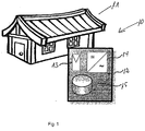
- FIG. 1 an island unit with a load unit 11 and an island power plant 12 is shown.
- the island power station 12 has a power generation unit 13, a network unit, In particular inverter unit 14 and an energy storage unit 15.
- the power generation unit 13 is preferably a photovoltaic system, wherein the invention is not limited to the generation of energy by solar energy, but can also recover energy from wind, biogas or other renewable resources.
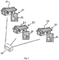
- FIG. 2 is an island energy network with a large number of island units of the FIG. 1 and a central control unit 40.
- Each of the further island units 20, 30 has identical components as the island unit 10.
- the control unit 40 generates and communicates power extraction requests and energy storage requests with each individual island unit. A communication between the island units 10, 20, 30 takes place in the island energy network of FIG. 2 not happening.
- the islanding unit 10 In order to solve an energy requirement or an energy surplus in the islanding unit 10, it is necessary for the islanding unit 10 to send a corresponding request to the central control unit 40, which in turn forwards it to island units 20, 30.
- the central control unit 40 If at least one of the island units 20, 30 is able to dissipate the energy requirement or excess of the island unit 10, it sends a corresponding signal to the central control unit 40, which then coordinates the energy flow between the island units 10, 20, 30 accordingly.
- the communication between the central control unit 40 and island units 10, 20, 30 is correspondingly complicated and cumbersome in accordance with the communication branching from and to the central control unit 40.
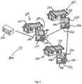
- FIG. 3 shows a (first) island unit 110, a second island unit 120 and a third island unit 130.
- the island unit 110 has a load unit 111 which consumes the energy generated, stored and / or taken from the power grid.
- the island unit 110 further includes an island power plant 112.
- the island power plant 112 has, for example, a photovoltaic system 113.
- the power generation unit 113 can also be any other facility that can generate energy from renewable resources.
- the island power station 112 also has an inverter 114 and an energy storage 115.
- the islanding unit 110 has an interface unit 116 which is designed to communicate energy extraction requests and / or energy storage requests with other island units, such as island units 120, 130 according to the invention. Furthermore, it is also possible for the island unit 110 according to the invention to communicate with conventional island units.
- the island units 120 and 130 are in the embodiment of the FIG. 3 equipped with analog units such as island unit 110.
- Island unit 120 comprises a load unit 121, an island power plant 122, a power generation unit 123, a network unit 124, an energy storage unit 125, and an interface unit 126.
- the island unit 130 has a load unit 131, an island power plant 132, a power generation unit 133, a network unit 134, an energy storage unit 135, and an interface unit 136.
- the island energy network of the invention FIG. 3 also has a management unit 140.
- the management unit 140 preferably communicates with the first islanding unit 110. In the same way, however, it is also possible for the management unit 140 to communicate with at least one of the islanding units 120 and 130.
- the operation of the island power grid 100 according to the invention is described below.
- the island unit 110 (and in the same way the island units 120, 130) generates energy from sunlight by means of the photovoltaic system 113.
- the photovoltaic system 113 In direct sunlight in particularly good weather conditions or in summer in the northern hemisphere of the earth, the photovoltaic system 113 generates energy very efficiently. If more energy is generated by the photovoltaic system 113 in the island unit 110 than the load unit 111 consumes (e.g., a household or a smaller operation), there is an excess of energy. This excess energy can, for example, be transferred to the energy storage unit 115 in order to charge a battery element of the storage unit 115. Also, the excess energy via the inverter 114 can be supplied to a power grid, e.g. a public energy network.
- the inverter 114 is preferably included in the load terminal unit of the island unit 110 via which the load unit 111 is connected to the island unit. Generated energy can thus be stored in the memory 115, dissipated into the power grid by means of the inverter 114 and consumed by the load unit by means of the inverter 114 or the load connection unit.
- the excess energy is passed into the storage unit 115 in order to charge it (almost) completely.
- the storage unit 115 is used, for example, at night, in bad weather, power failure, etc., as an emergency reserve to cover the energy needs of the load unit 111. Consists after the supply of generated energy to the load unit 111 and the charging of the memory element 115 continues Energy surplus, it can either be supplied to the (public) power grid and accounted for accordingly, or - according to the invention - are delivered to one (or more) island unit 120, 130 of the island energy network.
- the delivery can take place in this case in order to cover the energy requirement of another island unit 120, 130, or else to charge the energy storage units 125, 135 of the other island units 120, 130.
- the islanding unit 110 is configured according to the invention to access virtual power units 121, 131 and virtual memory units 125, 135 and to deliver energy to them. According to the invention, an energy requirement in the island units 120, 130 can thus be covered without having to resort to the public energy grid, which provides energy more expensively, inefficiently and ecologically with concern.
- An energy requirement in island unit 110 can arise, for example, because the photovoltaic system 113 generates less energy than the load unit 111 consumes. Such a situation may arise, for example, from the fact that the photovoltaic system 113 is less efficient due to bad weather conditions, in the winter in the northern hemisphere of the earth, or at night. If the photovoltaic unit 113 provides too little energy for the energy consumption of the load unit 111, the island unit 110 will first resort to the energy storage unit 115 in order to remove this energy and supply it to the load unit 111.
- the standalone unit 110 would have to resort to energy from the public power grid, which is more expensive, inefficient and ecologically more objectionable.
- the access to the public power grid can be prevented by the island unit 110 being able to cover its energy requirement from its virtual power generation units 123, 133 and / or its virtual memory units 125, 135.
- the island unit 110 sends an energy extraction request to at least one of the other island units 120, 130 via the interface unit 116.
- this corresponding other island unit 120, 130 will answer the energy extraction request of the island unit 110 and allow the island unit 110 extracts energy from the respective energy storage unit 125, 135 and / or the photovoltaic system 123, 133.
- the island units 110, 120, 130 can communicate with each other by means of the interface units 116, 126, 136, energy extraction requests and Energy storage requests exchange energy and largely avoid access to the public energy network.
- the management unit 140 is configured to send an energy storage request and / or power extraction request to one of the island units 110, 120, 130.
- the management unit 140 may also be in communication with a plurality of island units 110, 120, 130.
- at least one island unit 110 of the island energy grid is designed to send or forward a request to a further island unit 120, 130 in order to bring about a shortening of the communication in the form of virtualization.
- the management unit 140 may then serve, for example, as an interface between island power grids or an island power grid with the public power grid.
- the structure of the communication between the island units 110, 120, 130 can take place according to the invention in the form of a direct configuration in which each island unit 110 is informed by the island energy network, eg the management unit 140, with which island units 120, 130 it is to virtualize itself. It is also possible for the islanding unit 110 to initiate an active search in the island power grid or in an island power subnet by islanding unit 110 sending a ripple control signal within the island power grid to identify further island units 120, 130. Furthermore, it is also preferred that the islanding unit 110 initiate an active search eg on the Internet or via a radio network in order to receive identification information indicating with which island units 120, 130 it should connect.
- FIG. 4 shows a mean PV (photovoltaic) power production and average load of a 4 person household. The surplus of PV power during lunch time is clearly visible.
- an inventive approach is to no longer try to feed produced PV energy directly and completely into the grid, but always feed just as much PV power into the grid as it is currently consuming and surplus Caching PV energy.
- the size of the memory to be used is defined by different parameters, such as: a .: size of the PV system, amount of own consumption, security needs of the user, cost effectiveness etc.
- FIG. 5 shows a meter concept for determining the self-consumption of self-generated energy.
- Counters 2 and 3 can be integrated into one device.
- the island grid according to the invention is able to provide the currently consumed amount of electricity as needed at the same time.
- the energy is provided either directly from the PV plant, from the storage or even from a combination of both sources. Only when sufficient energy can not be made available from these sources is grid current used to cover, for example, short-term increasing demands. If the network is not available due to a failure, the system will be able to save generated power and / or, as needed, provide backup services up to a defined size from those required by the sources.
- FIG. 6 illustrates an embodiment of the invention. Inverter, battery charger and battery modules are integrated in one device. In addition, a backup line is provided, which can supply loads to the defined size in the event of a power failure.
- FIG. 6 shows a schematic representation of an island grid according to the invention for the optimization of PV-based self-consumption.
- the stand-alone grid integrates inverters, battery modules and battery charger in one device.
- another connection for the emergency supply is provided.
- the switches S1a and S1b are used to connect and disconnect loads to the emergency power supply and can be operated by the energy management.
- the island unit according to the invention has an intelligent system management which regulates and monitors the energy flows and the function of the components.
- the energy management measures the current load on all three phases and thus determines the load to be provided by the inverter.
- the Battery Converter a charge controller with a very high efficiency, stores excess PV power into the batteries, or removes the difference between the PV power and the power to be fed.
- the islanding unit compensates for the highly dynamic power fluctuations that characterize PV power and helps the inverter deliver the exact power.
- the system is equipped with a display to give the user and installer important information about the produced, stored and self-consumed electricity ( FIG. 7 ).
- the system provides a high degree of transparency regarding the performance of the own system and gives the installer important information about the system performance and supports it with any necessary maintenance work.
- FIG. 7 shows information about the plant performance provides a display.
- the present invention has a variety of approaches to the island unit users completely new ways of intelligent energy management.
- the system is designed on top of the kit principle, so that the installation by the professional installer can be done easily.
- Existing PV systems can also be retrofitted.
Landscapes
- Engineering & Computer Science (AREA)
- Power Engineering (AREA)
- Supply And Distribution Of Alternating Current (AREA)
- Charge And Discharge Circuits For Batteries Or The Like (AREA)
Claims (10)
- Procédé pour commander un réseau d'énergie à îlots (100), comprenant l'étape de communication d'une demande de prélèvement d'énergie et/ou d'une demande de stockage d'énergie entre une première unité d'îlot (110) et une deuxième unité d'îlot (120, 130), caractérisé en ce que l'étape suivante est en outre exécutée :sélection de l'unité d'îlot (110) à laquelle une unité de gestion (140) envoie la demande de prélèvement d'énergie et/ou la demande de stockage d'énergie conformément à une liste d'établissement des priorités, laquelle représente une hiérarchie prioritaire de la première unité d'îlot (110) et de la deuxième unité d'îlot (120, 130), et/ou conformément à une liste de prédiction qui représente une hiérarchie prédictive de la première unité d'îlot (110) et de la deuxième unité d'îlot (120, 130).
- Procédé selon la revendication 1, caractérisé en ce que le procédé comprend l'étape suivante :envoi d'une demande de prélèvement d'énergie et/ou d'une demande de stockage d'énergie de l'unité de gestion (140) à l'unité d'îlot (110, 120, 130) sélectionnée.
- Procédé selon la revendication 1 ou 2, caractérisé en ce que l'étape de communication comprend :réception de la demande de prélèvement d'énergie en vue de prélever de l'énergie de la première unité d'îlot (110) au niveau de la première unité d'îlot (110) de la part de la deuxième unité d'îlot (120, 130),envoi de la demande de prélèvement d'énergie en vue de prélever de l'énergie de la deuxième unité d'îlot (120, 130) de la première unité d'îlot (110) vers la deuxième unité d'îlot (120, 130),réception de la demande de stockage d'énergie en vue de stocker de l'énergie dans la première unité d'îlot (110) au niveau de la première unité d'îlot (110) de la part de la deuxième unité d'îlot (120, 130),- envoi de la demande de stockage d'énergie en vue de stocker de l'énergie dans la deuxième unité d'îlot (120, 130) de la première unité d'îlot (110) vers la deuxième unité d'îlot (120, 130), et/outransfert de la demande de prélèvement d'énergie et/ou de la demande de stockage d'énergie de la première unité d'îlot (110) à la deuxième unité d'îlot (120, 130).
- Procédé selon l'une des revendications 1 à 3, caractérisé en ce que le procédé comprend en outre l'étape suivante :sélection d'une deuxième unité d'îlot (120, 130) avec laquelle communique la première unité d'îlot (110), conformément à une liste d'établissement des priorités, laquelle représente une hiérarchie prioritaire de la deuxième unité d'îlot (120) et d'une troisième unité d'îlot (130), et/ou conformément à une liste de prédiction qui représente une hiérarchie prédictive de la deuxième unité d'îlot (120) et d'une troisième unité d'îlot (130).
- Procédé selon l'une des revendications 1 à 4, caractérisé en ce qu'une séquence donnée d'unités d'îlot (110, 120, 130) au sein du réseau d'énergie à îlots (100) est définie par le procédé, au sein de laquelle doivent être envoyées ou transférées les demandes.
- Procédé selon l'une des revendications 1 à 5, caractérisé en ce que la première unité d'îlot (110) sélectionnée se trouve sur la liste d'établissement des priorités avant la deuxième unité d'îlot (120, 130) lorsque la première unité d'îlot (110) est adaptée pour générer de l'énergie de manière plus favorable, plus fiable et plus efficacement que la deuxième unité d'îlot (120, 130).
- Procédé selon l'une des revendications 1 à 5, caractérisé en ce que la première unité d'îlot (110) sélectionnée se trouve sur la liste d'établissement des priorités avant la deuxième unité d'îlot (120, 130) s'il est connu, en se basant sur une période de référence ou sur des données relatives à la météorologie, à l'heure, au jour, à la semaine, à la saison, que la première unité d'îlot (110) est plus souvent adaptée que la deuxième unité d'îlot (120, 130) pour compenser un surplus d'énergie ou un besoin en énergie.
- Procédé selon l'une des revendications 1 à 7, caractérisé en ce que la hiérarchie prioritaire ou prédictive de la demande de prélèvement d'énergie pour la liste d'établissement des priorités ou la liste de prédiction est générée de manière autonome par le réseau d'énergie à îlots (100).
- Procédé selon l'une des revendications 1 à 8, caractérisé en ce que l'établissement des priorités ou la prédiction est effectué(e) par des données d'une interrogation de paramètres et de caractéristiques d'état, notamment de génération d'énergie momentanée ou de consommation momentanée d'une unité de charge, d'une ou plusieurs unités d'îlot (110, 120, 130) qui peuvent être regroupées sous la forme d'un sous-réseau à îlots.
- Procédé selon l'une des revendications 1 à 9, caractérisé en ce que l'unité d'îlot ou les unités d'îlot (110, 120, 130) sont configurées pour prédéfinir les réserves d'énergie qu'elles sont prêtes à délivrer au réseau d'énergie à îlots (100).
Priority Applications (1)
| Application Number | Priority Date | Filing Date | Title |
|---|---|---|---|
| EP17181492.4A EP3267549B1 (fr) | 2009-09-04 | 2010-09-02 | Unité d'îlot d'un réseau d'énergie en îlot destinée à communiquer de demandes d'énergie avec une autre unité d'îlot |
Applications Claiming Priority (1)
| Application Number | Priority Date | Filing Date | Title |
|---|---|---|---|
| DE102009040091A DE102009040091A1 (de) | 2009-09-04 | 2009-09-04 | Inseleinheit eines Inselenergienetzes zum Kommunizieren von Energieanfragen mit einer weiteren Inseleinheit |
Related Child Applications (2)
| Application Number | Title | Priority Date | Filing Date |
|---|---|---|---|
| EP17181492.4A Division EP3267549B1 (fr) | 2009-09-04 | 2010-09-02 | Unité d'îlot d'un réseau d'énergie en îlot destinée à communiquer de demandes d'énergie avec une autre unité d'îlot |
| EP17181492.4A Division-Into EP3267549B1 (fr) | 2009-09-04 | 2010-09-02 | Unité d'îlot d'un réseau d'énergie en îlot destinée à communiquer de demandes d'énergie avec une autre unité d'îlot |
Publications (3)
| Publication Number | Publication Date |
|---|---|
| EP2293409A2 EP2293409A2 (fr) | 2011-03-09 |
| EP2293409A3 EP2293409A3 (fr) | 2014-04-30 |
| EP2293409B1 true EP2293409B1 (fr) | 2017-11-15 |
Family
ID=43301952
Family Applications (2)
| Application Number | Title | Priority Date | Filing Date |
|---|---|---|---|
| EP10175111.3A Active EP2293409B1 (fr) | 2009-09-04 | 2010-09-02 | Unité d'îlot d'un réseau d'énergie en îlot pour la communication de demandes d'énergie avec une autre unité d'îlot |
| EP17181492.4A Active EP3267549B1 (fr) | 2009-09-04 | 2010-09-02 | Unité d'îlot d'un réseau d'énergie en îlot destinée à communiquer de demandes d'énergie avec une autre unité d'îlot |
Family Applications After (1)
| Application Number | Title | Priority Date | Filing Date |
|---|---|---|---|
| EP17181492.4A Active EP3267549B1 (fr) | 2009-09-04 | 2010-09-02 | Unité d'îlot d'un réseau d'énergie en îlot destinée à communiquer de demandes d'énergie avec une autre unité d'îlot |
Country Status (4)
| Country | Link |
|---|---|
| US (1) | US8803362B2 (fr) |
| EP (2) | EP2293409B1 (fr) |
| DE (1) | DE102009040091A1 (fr) |
| ES (1) | ES2659399T3 (fr) |
Families Citing this family (83)
| Publication number | Priority date | Publication date | Assignee | Title |
|---|---|---|---|---|
| US8806239B2 (en) | 2007-08-28 | 2014-08-12 | Causam Energy, Inc. | System, method, and apparatus for actively managing consumption of electric power supplied by one or more electric power grid operators |
| US12438368B2 (en) | 2007-08-28 | 2025-10-07 | Causam Enterprises, Inc. | System and method for estimating and providing dispatchable operating reserve energy capacity through use of active load management |
| US9177323B2 (en) | 2007-08-28 | 2015-11-03 | Causam Energy, Inc. | Systems and methods for determining and utilizing customer energy profiles for load control for individual structures, devices, and aggregation of same |
| US8890505B2 (en) | 2007-08-28 | 2014-11-18 | Causam Energy, Inc. | System and method for estimating and providing dispatchable operating reserve energy capacity through use of active load management |
| US9130402B2 (en) | 2007-08-28 | 2015-09-08 | Causam Energy, Inc. | System and method for generating and providing dispatchable operating reserve energy capacity through use of active load management |
| US10295969B2 (en) | 2007-08-28 | 2019-05-21 | Causam Energy, Inc. | System and method for generating and providing dispatchable operating reserve energy capacity through use of active load management |
| US8805552B2 (en) | 2007-08-28 | 2014-08-12 | Causam Energy, Inc. | Method and apparatus for actively managing consumption of electric power over an electric power grid |
| JP5630176B2 (ja) * | 2010-09-16 | 2014-11-26 | ソニー株式会社 | 電力供給装置 |
| DE102010048809A1 (de) * | 2010-10-20 | 2012-04-26 | Hüttinger Elektronik Gmbh + Co. Kg | Leistungsversorgungssystem für eine Plasmaanwendung und/oder eine Induktionserwärmungsanwendung |
| US8682495B2 (en) * | 2010-10-21 | 2014-03-25 | The Boeing Company | Microgrid control system |
| US8754547B2 (en) * | 2010-11-17 | 2014-06-17 | Battelle Memorial Institute | Controller for hybrid energy storage |
| GB2486016A (en) * | 2010-12-02 | 2012-06-06 | Sony Corp | Control of storage devices in an electric power network |
| US9300139B2 (en) * | 2010-12-16 | 2016-03-29 | Ashot Nazarian | Method and apparatus for integrated electric power generation, storage and supply distributed and networked at the same time |
| US9281690B2 (en) * | 2010-12-21 | 2016-03-08 | Palo Alto Research Center Incorporated | Tactical smart grids |
| WO2012139657A2 (fr) * | 2011-04-15 | 2012-10-18 | Siemens Aktiengesellschaft | Réseau de distribution d'énergie et son procédé de fonctionnement |
| FR2976137A1 (fr) * | 2011-05-31 | 2012-12-07 | Soitec Silicon On Insulator Technologies | Dispositif modulaire de production d'energie electrique |
| US9461488B2 (en) | 2011-06-09 | 2016-10-04 | Henry Shum | Battery with integrated power inverter |
| US9124098B2 (en) * | 2011-08-08 | 2015-09-01 | General Electric Company | Managing excess renewable energy |
| DE102011111972A1 (de) * | 2011-08-31 | 2013-02-28 | Kostal Industrie Elektrik Gmbh | Energieverteilungsanlage mit einer Steuervorrichtung und einem Stromsensor |
| CN102355006B (zh) * | 2011-09-28 | 2013-06-26 | 东北电力大学 | 一种风光储联合并网发电协调控制方法 |
| US8751036B2 (en) | 2011-09-28 | 2014-06-10 | Causam Energy, Inc. | Systems and methods for microgrid power generation management with selective disconnect |
| US8862279B2 (en) | 2011-09-28 | 2014-10-14 | Causam Energy, Inc. | Systems and methods for optimizing microgrid power generation and management with predictive modeling |
| US9225173B2 (en) | 2011-09-28 | 2015-12-29 | Causam Energy, Inc. | Systems and methods for microgrid power generation and management |
| ES2437184B1 (es) * | 2011-12-28 | 2014-12-04 | Kenus Informatica, S.L. | Procedimiento de gestión de producción eléctrica y dispositivo para su aplicación |
| US9502898B2 (en) * | 2012-02-01 | 2016-11-22 | General Electric Company | Systems and methods for managing a power distribution system |
| DE102012101799A1 (de) * | 2012-03-02 | 2013-09-05 | ropa development GmbH | Netzinfrastrukturkomponente, Verbundsystem mit einer Mehrzahl von Netzinfrastrukturkomponenten sowie Verwendung des Verbundsystems |
| US9465398B2 (en) | 2012-06-20 | 2016-10-11 | Causam Energy, Inc. | System and methods for actively managing electric power over an electric power grid |
| US9207698B2 (en) | 2012-06-20 | 2015-12-08 | Causam Energy, Inc. | Method and apparatus for actively managing electric power over an electric power grid |
| US9461471B2 (en) | 2012-06-20 | 2016-10-04 | Causam Energy, Inc | System and methods for actively managing electric power over an electric power grid and providing revenue grade date usable for settlement |
| US9563215B2 (en) | 2012-07-14 | 2017-02-07 | Causam Energy, Inc. | Method and apparatus for actively managing electric power supply for an electric power grid |
| US8849715B2 (en) * | 2012-10-24 | 2014-09-30 | Causam Energy, Inc. | System, method, and apparatus for settlement for participation in an electric power grid |
| US10475138B2 (en) | 2015-09-23 | 2019-11-12 | Causam Energy, Inc. | Systems and methods for advanced energy network |
| US8983669B2 (en) | 2012-07-31 | 2015-03-17 | Causam Energy, Inc. | System, method, and data packets for messaging for electric power grid elements over a secure internet protocol network |
| US10861112B2 (en) | 2012-07-31 | 2020-12-08 | Causam Energy, Inc. | Systems and methods for advanced energy settlements, network-based messaging, and applications supporting the same on a blockchain platform |
| US9513648B2 (en) | 2012-07-31 | 2016-12-06 | Causam Energy, Inc. | System, method, and apparatus for electric power grid and network management of grid elements |
| DE102012214463A1 (de) * | 2012-08-14 | 2014-02-20 | Tim Meyer | Vorrichtung und Verfahren zur Stromeinspeisung aus einer oder mehreren Stromerzeugungs-oder Speicheranlagen in zwei oder mehr Einspeisungspunkte |
| US8981709B1 (en) * | 2012-08-22 | 2015-03-17 | Edee, LLC | Supplemental electrical generation apparatus and method |
| US9093582B2 (en) | 2012-09-19 | 2015-07-28 | Opterra Energy Services, Inc. | Solar canopy assembly |
| US9093583B2 (en) | 2012-09-19 | 2015-07-28 | Opterra Energy Services, Inc. | Folding solar canopy assembly |
| US20140077055A1 (en) | 2012-09-19 | 2014-03-20 | Chevron U.S.A Inc.. | Bracing assembly |
| US9312699B2 (en) | 2012-10-11 | 2016-04-12 | Flexgen Power Systems, Inc. | Island grid power supply apparatus and methods using energy storage for transient stabilization |
| US10289080B2 (en) | 2012-10-11 | 2019-05-14 | Flexgen Power Systems, Inc. | Multi-generator applications using variable speed and solid state generators for efficiency and frequency stabilization |
| US9948139B2 (en) | 2012-10-26 | 2018-04-17 | Solpad, Inc. | Solar power generation, distribution, and communication system |
| US9620993B2 (en) | 2012-10-26 | 2017-04-11 | Solpad, Inc. | Auto-synchronous isolated inlet power converter |
| US9444397B2 (en) | 2012-10-26 | 2016-09-13 | Sunculture Solar, Inc. | Integrated solar panel |
| EP2904679B1 (fr) * | 2012-12-11 | 2018-05-16 | Siemens Aktiengesellschaft | Procédé de contrôle du fonctionnement des générateurs d'énergie électrique et dispositif de commande pour la mise en oeuvre de ce procédé |
| US9568900B2 (en) * | 2012-12-11 | 2017-02-14 | Opterra Energy Services, Inc. | Systems and methods for regulating an alternative energy source that is decoupled from a power grid |
| EP2959561A4 (fr) * | 2013-02-19 | 2016-09-14 | Solantro Semiconductor Corp | Miniréseaux à autoformation |
| US9553517B2 (en) | 2013-03-01 | 2017-01-24 | Fllexgen Power Systems, Inc. | Hybrid energy storage system and methods |
| DE102013011087A1 (de) * | 2013-07-03 | 2015-01-08 | RWE Supply & Trading GmbH | Verfahren zur Regelung des Gasbezuges für mehrere Gasverbraucher aus einem Gastransportnetz |
| ITVR20130055U1 (it) * | 2013-12-04 | 2015-06-05 | Drives And Motors D O O | Sistema per la generazione e la distribuzione di energia elettrica ricavata preferibilmente da fonti rinnovabili |
| JP6365550B2 (ja) * | 2014-01-08 | 2018-08-01 | ソニー株式会社 | 電力制御装置及び電力制御方法 |
| DE102014100690A1 (de) * | 2014-01-22 | 2015-07-23 | Sma Solar Technology Ag | Wechselrichter, insbesondere als teil eines energieerzeugungsverbundes, und verfahren |
| JP6355017B2 (ja) * | 2014-04-11 | 2018-07-11 | パナソニックIpマネジメント株式会社 | 電源制御装置及び電源制御方法 |
| CN104242335B (zh) * | 2014-06-30 | 2016-08-17 | 江苏华大天益电力科技有限公司 | 一种基于额定容量的风光储发电单元容量优化配置方法 |
| DE102014009953A1 (de) | 2014-07-07 | 2016-01-07 | LichtBlick SE | System und Verfahren zum Bestimmen der Eignung mehrerer elektrischer Produzenten und Verbraucher, die in einem Netzwerk als virtuelles Kraftwerk betrieben werden, für die Erbringung von Regelleistung |
| JP6237514B2 (ja) | 2014-07-17 | 2017-11-29 | ソニー株式会社 | 送受電制御装置、送受電制御方法及び送受電制御システム |
| JP6248859B2 (ja) | 2014-08-08 | 2017-12-20 | ソニー株式会社 | 電力供給装置、電力供給方法及び電力供給システム |
| AT516213B1 (de) | 2014-09-02 | 2016-08-15 | Franz Schweighofer | Energieversorgungssystem |
| US10116560B2 (en) | 2014-10-20 | 2018-10-30 | Causam Energy, Inc. | Systems, methods, and apparatus for communicating messages of distributed private networks over multiple public communication networks |
| US9830672B2 (en) * | 2014-10-29 | 2017-11-28 | Solarcity Corporation | Power management message bus system |
| US20170271912A1 (en) * | 2014-12-16 | 2017-09-21 | Sinewatts, Inc. | Dispatchable photovoltaic panel with fully integrated energy storage and grid interactive power conversion |
| EP3241262B1 (fr) | 2014-12-30 | 2020-08-19 | Flexgen Power Systems, Inc. | Dispositif de stabilisation de puissance transitoire à régulation de puissance active et réactive |
| CN104682428A (zh) * | 2015-02-04 | 2015-06-03 | 顾为东 | 一种高效节能的电力网络的运行方法 |
| JP6505460B2 (ja) * | 2015-02-18 | 2019-04-24 | 積水化学工業株式会社 | 電力管理システム、電力管理方法及びプログラム |
| CN105244879B (zh) * | 2015-11-18 | 2017-11-03 | 国家电网公司 | 考虑核电机组检修的核电抽水储能电站联合运行优化方法 |
| NL2016736B1 (nl) * | 2016-05-06 | 2017-11-14 | Lens-Ip B V | Systeem voor het verdelen van stroom en werkwijze. |
| US10139847B2 (en) * | 2016-05-18 | 2018-11-27 | Solarcity Corporation | Systems and methods for controlling PV production within energy export constraints |
| CN106356892B (zh) * | 2016-10-14 | 2019-07-09 | 易事特集团股份有限公司 | 微电网黑启动方法 |
| US11309714B2 (en) * | 2016-11-02 | 2022-04-19 | Tesla, Inc. | Micro-batteries for energy generation systems |
| CN106849835B (zh) * | 2017-03-13 | 2018-09-07 | 东北电力大学 | 一种风光氢综合能源系统在线能量调控方法 |
| WO2018188872A1 (fr) | 2017-04-13 | 2018-10-18 | Sma Solar Technology Ag | Système de distribution d'une énergie localement produite sur plusieurs unités de charge |
| US10693296B2 (en) | 2017-05-03 | 2020-06-23 | International Business Machines Corporation | Stabilizing consumer energy demand |
| EP3622466A1 (fr) * | 2017-07-05 | 2020-03-18 | Siemens Aktiengesellschaft | Procédé permettant le commerce d'énergie électrique entre de petits producteurs et des consommateurs finals |
| US10742037B2 (en) | 2018-07-02 | 2020-08-11 | International Business Machines Corporation | Managing consumer energy demand |
| US11581741B2 (en) * | 2018-11-06 | 2023-02-14 | BoxPower Inc. | Design, deployment, and operation of modular microgrid with intelligent energy management |
| US11172423B2 (en) | 2018-12-31 | 2021-11-09 | Itron, Inc. | Solar-powered access point for load balancing network traffic across backhaul networks |
| US11296539B2 (en) * | 2018-12-31 | 2022-04-05 | Itron, Inc. | Solar hybrid battery for powering network devices over extended time intervals |
| US11184831B2 (en) | 2018-12-31 | 2021-11-23 | Itron, Inc. | Solar-powered relay for coupling remotely-located leaf nodes to a wireless network |
| CN110138014B (zh) * | 2019-06-18 | 2022-11-29 | 深圳市尚科新能源有限公司 | 并网离网一体化的太阳能发电子系统及系统 |
| FR3105864B1 (fr) * | 2019-12-30 | 2023-11-24 | Commissariat Energie Atomique | Procédé de gestion automatique d’un flux d’énergie électrique |
| CN113410866A (zh) * | 2020-12-03 | 2021-09-17 | 广东电网有限责任公司广州供电局 | 一种虚拟电厂在线功率自动调节装置及其调节方法 |
| US20240243573A1 (en) * | 2023-01-12 | 2024-07-18 | Schweitzer Engineering Laboratories, Inc. | Asynchronous distributed control design using tiered automation algorithms |
Family Cites Families (9)
| Publication number | Priority date | Publication date | Assignee | Title |
|---|---|---|---|---|
| DE59502398D1 (de) * | 1994-09-21 | 1998-07-09 | Inventio Ag | Verfahren und Einrichtung zur variablen Zuteilung von in Betrieb stehenden Umrichtern auf mindestens eine Last |
| AU2002212993A1 (en) * | 2000-09-28 | 2002-04-08 | Youtility Inc | Local area grid for distributed power |
| US7385373B2 (en) * | 2003-06-30 | 2008-06-10 | Gaia Power Technologies, Inc. | Intelligent distributed energy storage system for demand side power management |
| US7844370B2 (en) * | 2006-08-10 | 2010-11-30 | Gridpoint, Inc. | Scheduling and control in a power aggregation system for distributed electric resources |
| EP2075891B1 (fr) * | 2006-10-16 | 2014-01-01 | Vpec, Inc. | Systeme d'alimentation electrique |
| CN101765959B (zh) * | 2007-05-08 | 2015-04-15 | 美国电力转换有限公司 | 交流电源能量管理 |
| WO2009145678A1 (fr) * | 2008-05-26 | 2009-12-03 | Volvo Technology Corporation | Module interrupteur pour un réseau d'alimentation électrique et réseau d'alimentation électrique comprenant au moins un module interrupteur |
| US8200370B2 (en) * | 2008-12-04 | 2012-06-12 | American Power Conversion Corporation | Energy reduction |
| US8463561B2 (en) * | 2010-02-26 | 2013-06-11 | Changers Llc | Stand-alone renewable-energy generating device including emission savings sensor, retrofit emissions savings sensor for such a device, and method |
-
2009
- 2009-09-04 DE DE102009040091A patent/DE102009040091A1/de not_active Withdrawn
-
2010
- 2010-09-02 EP EP10175111.3A patent/EP2293409B1/fr active Active
- 2010-09-02 ES ES10175111.3T patent/ES2659399T3/es active Active
- 2010-09-02 EP EP17181492.4A patent/EP3267549B1/fr active Active
- 2010-09-03 US US12/875,945 patent/US8803362B2/en active Active
Non-Patent Citations (1)
| Title |
|---|
| None * |
Also Published As
| Publication number | Publication date |
|---|---|
| EP3267549B1 (fr) | 2020-08-05 |
| DE102009040091A1 (de) | 2011-03-10 |
| EP2293409A3 (fr) | 2014-04-30 |
| EP2293409A2 (fr) | 2011-03-09 |
| EP3267549A1 (fr) | 2018-01-10 |
| US8803362B2 (en) | 2014-08-12 |
| ES2659399T3 (es) | 2018-03-15 |
| US20110080044A1 (en) | 2011-04-07 |
Similar Documents
| Publication | Publication Date | Title |
|---|---|---|
| EP2293409B1 (fr) | Unité d'îlot d'un réseau d'énergie en îlot pour la communication de demandes d'énergie avec une autre unité d'îlot | |
| EP2293410B1 (fr) | Dispositif de commande d'énergie pour un réseau d'énergie avec une unité de commande pour commander un flux d'énergie entre l'unité de production d'énergie, l'unité de stockage d'énergie, l'unité de chargement et/ou le réseau d'énergie | |
| EP3381102B1 (fr) | Installation d'énergie à domicile et procédé d'exploitation d'une installation d'énergie à domicile | |
| Ullah et al. | Assessment of technical and financial benefits of AC and DC microgrids based on solar photovoltaic | |
| DE102020205128A1 (de) | Verfahren zum Laden einer Batterie eines elektrischen Verbrauchers sowie Ladestation mit einer Steuerungseinheit zur Ausführung eines derartigen Verfahrens | |
| JP6017715B1 (ja) | 太陽光発電システム | |
| EP3590169B1 (fr) | Procédé de gestion d'énergie pour système énergétique et système énergétique | |
| DE102019112270A1 (de) | Anordnung und Verfahren zur Energieverbrauchssteuerung | |
| EP3406016B1 (fr) | Système de distribution d'une énergie localement produite sur plusieurs unités de charge | |
| DE102011090141A1 (de) | Verfahren und Vorrichtung zur Nutzung elektrischer Energie einer an ein Hausstromnetz angeschlossenen Einrichtung zur Erzeugung erneuerbarer elektrischer Energie | |
| WO2014023724A2 (fr) | Système accumulateur photovoltaïque | |
| Vetter et al. | Lithium-ion batteries for storage of renewable energies and electric grid backup | |
| AT510795A1 (de) | Verfahren zum dezentralen energiemanagement für ladestationen für elektrofahrzeuge | |
| DE102015109113B4 (de) | Speichereinheit für einen Verbraucher, Speichersystem sowie Verfahren zur Steuerung eines Speichersystems | |
| DE102011010791A1 (de) | System zur Erzeugung regenerativer elektrischer Energie mit intelligenter Energieverwaltungseinheit | |
| Tsao et al. | Distributed energy storage system planning in relation to renewable energy investment | |
| DE102010001874A1 (de) | Speicher für elektrische Energie | |
| DE102012011119A1 (de) | Lokales Energiesystem | |
| DE102010036087A1 (de) | Verfahren und Anordnung zum Versorgen eines Verbrauchers mit elektrischer Energie | |
| EP3042433A1 (fr) | Procédé et dispositif permettant la gestion optimale pour un système d'accumulation d'un système photovoltaïque | |
| Hamdaoui et al. | Optimized energy management of electric vehicles connected to microgrid | |
| EP3490093A1 (fr) | Réseaux et procédés d'alimentation en énergie | |
| DE102023120803A1 (de) | Steuerungsmodul, Gerät und Energiespeichersystem | |
| DE102023124449A1 (de) | System mit einem Rechenzentrum, sowie Verbund mit dem System und wenigstens einem Rechenzentrum | |
| DE102023124448A1 (de) | Verbund mit dezentral verteilten Systemen sowie Verfahren zum Betreiben eines solchen Verbundes |
Legal Events
| Date | Code | Title | Description |
|---|---|---|---|
| PUAI | Public reference made under article 153(3) epc to a published international application that has entered the european phase |
Free format text: ORIGINAL CODE: 0009012 |
|
| AK | Designated contracting states |
Kind code of ref document: A2 Designated state(s): AL AT BE BG CH CY CZ DE DK EE ES FI FR GB GR HR HU IE IS IT LI LT LU LV MC MK MT NL NO PL PT RO SE SI SK SM TR |
|
| AX | Request for extension of the european patent |
Extension state: BA ME RS |
|
| RAP1 | Party data changed (applicant data changed or rights of an application transferred) |
Owner name: ROBERT BOSCH GMBH |
|
| PUAL | Search report despatched |
Free format text: ORIGINAL CODE: 0009013 |
|
| AK | Designated contracting states |
Kind code of ref document: A3 Designated state(s): AL AT BE BG CH CY CZ DE DK EE ES FI FR GB GR HR HU IE IS IT LI LT LU LV MC MK MT NL NO PL PT RO SE SI SK SM TR |
|
| AX | Request for extension of the european patent |
Extension state: BA ME RS |
|
| RIC1 | Information provided on ipc code assigned before grant |
Ipc: H02J 3/38 20060101AFI20140321BHEP |
|
| 17P | Request for examination filed |
Effective date: 20141030 |
|
| RBV | Designated contracting states (corrected) |
Designated state(s): AL AT BE BG CH CY CZ DE DK EE ES FI FR GB GR HR HU IE IS IT LI LT LU LV MC MK MT NL NO PL PT RO SE SI SK SM TR |
|
| 17Q | First examination report despatched |
Effective date: 20160502 |
|
| GRAP | Despatch of communication of intention to grant a patent |
Free format text: ORIGINAL CODE: EPIDOSNIGR1 |
|
| INTG | Intention to grant announced |
Effective date: 20170418 |
|
| GRAS | Grant fee paid |
Free format text: ORIGINAL CODE: EPIDOSNIGR3 |
|
| GRAA | (expected) grant |
Free format text: ORIGINAL CODE: 0009210 |
|
| AK | Designated contracting states |
Kind code of ref document: B1 Designated state(s): AL AT BE BG CH CY CZ DE DK EE ES FI FR GB GR HR HU IE IS IT LI LT LU LV MC MK MT NL NO PL PT RO SE SI SK SM TR |
|
| REG | Reference to a national code |
Ref country code: CH Ref legal event code: EP Ref country code: GB Ref legal event code: FG4D Free format text: NOT ENGLISH Ref country code: AT Ref legal event code: REF Ref document number: 947158 Country of ref document: AT Kind code of ref document: T Effective date: 20171115 |
|
| REG | Reference to a national code |
Ref country code: IE Ref legal event code: FG4D Free format text: LANGUAGE OF EP DOCUMENT: GERMAN |
|
| REG | Reference to a national code |
Ref country code: DE Ref legal event code: R096 Ref document number: 502010014374 Country of ref document: DE |
|
| REG | Reference to a national code |
Ref country code: ES Ref legal event code: FG2A Ref document number: 2659399 Country of ref document: ES Kind code of ref document: T3 Effective date: 20180315 |
|
| REG | Reference to a national code |
Ref country code: NL Ref legal event code: MP Effective date: 20171115 |
|
| REG | Reference to a national code |
Ref country code: LT Ref legal event code: MG4D |
|
| PG25 | Lapsed in a contracting state [announced via postgrant information from national office to epo] |
Ref country code: NL Free format text: LAPSE BECAUSE OF FAILURE TO SUBMIT A TRANSLATION OF THE DESCRIPTION OR TO PAY THE FEE WITHIN THE PRESCRIBED TIME-LIMIT Effective date: 20171115 Ref country code: FI Free format text: LAPSE BECAUSE OF FAILURE TO SUBMIT A TRANSLATION OF THE DESCRIPTION OR TO PAY THE FEE WITHIN THE PRESCRIBED TIME-LIMIT Effective date: 20171115 Ref country code: LT Free format text: LAPSE BECAUSE OF FAILURE TO SUBMIT A TRANSLATION OF THE DESCRIPTION OR TO PAY THE FEE WITHIN THE PRESCRIBED TIME-LIMIT Effective date: 20171115 Ref country code: NO Free format text: LAPSE BECAUSE OF FAILURE TO SUBMIT A TRANSLATION OF THE DESCRIPTION OR TO PAY THE FEE WITHIN THE PRESCRIBED TIME-LIMIT Effective date: 20180215 Ref country code: SE Free format text: LAPSE BECAUSE OF FAILURE TO SUBMIT A TRANSLATION OF THE DESCRIPTION OR TO PAY THE FEE WITHIN THE PRESCRIBED TIME-LIMIT Effective date: 20171115 |
|
| PG25 | Lapsed in a contracting state [announced via postgrant information from national office to epo] |
Ref country code: GR Free format text: LAPSE BECAUSE OF FAILURE TO SUBMIT A TRANSLATION OF THE DESCRIPTION OR TO PAY THE FEE WITHIN THE PRESCRIBED TIME-LIMIT Effective date: 20180216 Ref country code: LV Free format text: LAPSE BECAUSE OF FAILURE TO SUBMIT A TRANSLATION OF THE DESCRIPTION OR TO PAY THE FEE WITHIN THE PRESCRIBED TIME-LIMIT Effective date: 20171115 Ref country code: BG Free format text: LAPSE BECAUSE OF FAILURE TO SUBMIT A TRANSLATION OF THE DESCRIPTION OR TO PAY THE FEE WITHIN THE PRESCRIBED TIME-LIMIT Effective date: 20180215 Ref country code: HR Free format text: LAPSE BECAUSE OF FAILURE TO SUBMIT A TRANSLATION OF THE DESCRIPTION OR TO PAY THE FEE WITHIN THE PRESCRIBED TIME-LIMIT Effective date: 20171115 |
|
| PG25 | Lapsed in a contracting state [announced via postgrant information from national office to epo] |
Ref country code: SK Free format text: LAPSE BECAUSE OF FAILURE TO SUBMIT A TRANSLATION OF THE DESCRIPTION OR TO PAY THE FEE WITHIN THE PRESCRIBED TIME-LIMIT Effective date: 20171115 Ref country code: EE Free format text: LAPSE BECAUSE OF FAILURE TO SUBMIT A TRANSLATION OF THE DESCRIPTION OR TO PAY THE FEE WITHIN THE PRESCRIBED TIME-LIMIT Effective date: 20171115 Ref country code: CY Free format text: LAPSE BECAUSE OF FAILURE TO SUBMIT A TRANSLATION OF THE DESCRIPTION OR TO PAY THE FEE WITHIN THE PRESCRIBED TIME-LIMIT Effective date: 20171115 Ref country code: DK Free format text: LAPSE BECAUSE OF FAILURE TO SUBMIT A TRANSLATION OF THE DESCRIPTION OR TO PAY THE FEE WITHIN THE PRESCRIBED TIME-LIMIT Effective date: 20171115 Ref country code: CZ Free format text: LAPSE BECAUSE OF FAILURE TO SUBMIT A TRANSLATION OF THE DESCRIPTION OR TO PAY THE FEE WITHIN THE PRESCRIBED TIME-LIMIT Effective date: 20171115 |
|
| REG | Reference to a national code |
Ref country code: DE Ref legal event code: R097 Ref document number: 502010014374 Country of ref document: DE |
|
| PG25 | Lapsed in a contracting state [announced via postgrant information from national office to epo] |
Ref country code: SM Free format text: LAPSE BECAUSE OF FAILURE TO SUBMIT A TRANSLATION OF THE DESCRIPTION OR TO PAY THE FEE WITHIN THE PRESCRIBED TIME-LIMIT Effective date: 20171115 Ref country code: PL Free format text: LAPSE BECAUSE OF FAILURE TO SUBMIT A TRANSLATION OF THE DESCRIPTION OR TO PAY THE FEE WITHIN THE PRESCRIBED TIME-LIMIT Effective date: 20171115 Ref country code: RO Free format text: LAPSE BECAUSE OF FAILURE TO SUBMIT A TRANSLATION OF THE DESCRIPTION OR TO PAY THE FEE WITHIN THE PRESCRIBED TIME-LIMIT Effective date: 20171115 |
|
| PLBE | No opposition filed within time limit |
Free format text: ORIGINAL CODE: 0009261 |
|
| REG | Reference to a national code |
Ref country code: FR Ref legal event code: PLFP Year of fee payment: 9 |
|
| STAA | Information on the status of an ep patent application or granted ep patent |
Free format text: STATUS: NO OPPOSITION FILED WITHIN TIME LIMIT |
|
| PG25 | Lapsed in a contracting state [announced via postgrant information from national office to epo] |
Ref country code: MT Free format text: LAPSE BECAUSE OF FAILURE TO SUBMIT A TRANSLATION OF THE DESCRIPTION OR TO PAY THE FEE WITHIN THE PRESCRIBED TIME-LIMIT Effective date: 20171115 |
|
| 26N | No opposition filed |
Effective date: 20180817 |
|
| PG25 | Lapsed in a contracting state [announced via postgrant information from national office to epo] |
Ref country code: SI Free format text: LAPSE BECAUSE OF FAILURE TO SUBMIT A TRANSLATION OF THE DESCRIPTION OR TO PAY THE FEE WITHIN THE PRESCRIBED TIME-LIMIT Effective date: 20171115 |
|
| PG25 | Lapsed in a contracting state [announced via postgrant information from national office to epo] |
Ref country code: MC Free format text: LAPSE BECAUSE OF FAILURE TO SUBMIT A TRANSLATION OF THE DESCRIPTION OR TO PAY THE FEE WITHIN THE PRESCRIBED TIME-LIMIT Effective date: 20171115 |
|
| REG | Reference to a national code |
Ref country code: CH Ref legal event code: PL |
|
| REG | Reference to a national code |
Ref country code: BE Ref legal event code: MM Effective date: 20180930 |
|
| REG | Reference to a national code |
Ref country code: IE Ref legal event code: MM4A |
|
| PG25 | Lapsed in a contracting state [announced via postgrant information from national office to epo] |
Ref country code: LU Free format text: LAPSE BECAUSE OF NON-PAYMENT OF DUE FEES Effective date: 20180902 |
|
| PG25 | Lapsed in a contracting state [announced via postgrant information from national office to epo] |
Ref country code: IE Free format text: LAPSE BECAUSE OF NON-PAYMENT OF DUE FEES Effective date: 20180902 |
|
| PG25 | Lapsed in a contracting state [announced via postgrant information from national office to epo] |
Ref country code: LI Free format text: LAPSE BECAUSE OF NON-PAYMENT OF DUE FEES Effective date: 20180930 Ref country code: BE Free format text: LAPSE BECAUSE OF NON-PAYMENT OF DUE FEES Effective date: 20180930 Ref country code: CH Free format text: LAPSE BECAUSE OF NON-PAYMENT OF DUE FEES Effective date: 20180930 |
|
| REG | Reference to a national code |
Ref country code: AT Ref legal event code: MM01 Ref document number: 947158 Country of ref document: AT Kind code of ref document: T Effective date: 20180902 |
|
| PG25 | Lapsed in a contracting state [announced via postgrant information from national office to epo] |
Ref country code: AT Free format text: LAPSE BECAUSE OF NON-PAYMENT OF DUE FEES Effective date: 20180902 |
|
| PG25 | Lapsed in a contracting state [announced via postgrant information from national office to epo] |
Ref country code: TR Free format text: LAPSE BECAUSE OF FAILURE TO SUBMIT A TRANSLATION OF THE DESCRIPTION OR TO PAY THE FEE WITHIN THE PRESCRIBED TIME-LIMIT Effective date: 20171115 |
|
| PG25 | Lapsed in a contracting state [announced via postgrant information from national office to epo] |
Ref country code: HU Free format text: LAPSE BECAUSE OF FAILURE TO SUBMIT A TRANSLATION OF THE DESCRIPTION OR TO PAY THE FEE WITHIN THE PRESCRIBED TIME-LIMIT; INVALID AB INITIO Effective date: 20100902 Ref country code: PT Free format text: LAPSE BECAUSE OF FAILURE TO SUBMIT A TRANSLATION OF THE DESCRIPTION OR TO PAY THE FEE WITHIN THE PRESCRIBED TIME-LIMIT Effective date: 20171115 |
|
| PG25 | Lapsed in a contracting state [announced via postgrant information from national office to epo] |
Ref country code: MK Free format text: LAPSE BECAUSE OF NON-PAYMENT OF DUE FEES Effective date: 20171115 |
|
| PG25 | Lapsed in a contracting state [announced via postgrant information from national office to epo] |
Ref country code: AL Free format text: LAPSE BECAUSE OF FAILURE TO SUBMIT A TRANSLATION OF THE DESCRIPTION OR TO PAY THE FEE WITHIN THE PRESCRIBED TIME-LIMIT Effective date: 20171115 Ref country code: IS Free format text: LAPSE BECAUSE OF FAILURE TO SUBMIT A TRANSLATION OF THE DESCRIPTION OR TO PAY THE FEE WITHIN THE PRESCRIBED TIME-LIMIT Effective date: 20180315 |
|
| PGFP | Annual fee paid to national office [announced via postgrant information from national office to epo] |
Ref country code: GB Payment date: 20250923 Year of fee payment: 16 |
|
| PGFP | Annual fee paid to national office [announced via postgrant information from national office to epo] |
Ref country code: FR Payment date: 20250922 Year of fee payment: 16 |
|
| PGFP | Annual fee paid to national office [announced via postgrant information from national office to epo] |
Ref country code: DE Payment date: 20251121 Year of fee payment: 16 |
|
| PGFP | Annual fee paid to national office [announced via postgrant information from national office to epo] |
Ref country code: IT Payment date: 20250930 Year of fee payment: 16 |
|
| PGFP | Annual fee paid to national office [announced via postgrant information from national office to epo] |
Ref country code: ES Payment date: 20251020 Year of fee payment: 16 |