EP2293425A2 - Fahrzeugdrehstromgenerator und Gleichrichter eines Fahrzeugdrehstromgenerators - Google Patents
Fahrzeugdrehstromgenerator und Gleichrichter eines Fahrzeugdrehstromgenerators Download PDFInfo
- Publication number
- EP2293425A2 EP2293425A2 EP10173229A EP10173229A EP2293425A2 EP 2293425 A2 EP2293425 A2 EP 2293425A2 EP 10173229 A EP10173229 A EP 10173229A EP 10173229 A EP10173229 A EP 10173229A EP 2293425 A2 EP2293425 A2 EP 2293425A2
- Authority
- EP
- European Patent Office
- Prior art keywords
- rectifier
- drive signal
- mos fets
- gate
- mos
- Prior art date
- Legal status (The legal status is an assumption and is not a legal conclusion. Google has not performed a legal analysis and makes no representation as to the accuracy of the status listed.)
- Withdrawn
Links
Images


Classifications
-
- H—ELECTRICITY
- H02—GENERATION; CONVERSION OR DISTRIBUTION OF ELECTRIC POWER
- H02M—APPARATUS FOR CONVERSION BETWEEN AC AND AC, BETWEEN AC AND DC, OR BETWEEN DC AND DC, AND FOR USE WITH MAINS OR SIMILAR POWER SUPPLY SYSTEMS; CONVERSION OF DC OR AC INPUT POWER INTO SURGE OUTPUT POWER; CONTROL OR REGULATION THEREOF
- H02M7/00—Conversion of AC power input into DC power output; Conversion of DC power input into AC power output
- H02M7/02—Conversion of AC power input into DC power output without possibility of reversal
Definitions
- the present invention relates to a vehicular alternator that uses MOS FETs as rectifier elements, and to a rectifier for a vehicular alternator.
- gate drive signal lines have been connected between the chassis in which the MOS FET control circuit is housed and the chassis in which the full-wave rectifier circuit is housed.
- the MOS FET control circuit and the full-wave rectifier circuit are directly attached to a chassis for fixing the AC generator to the engine. Due to this, the MOS FET control circuit and the full-wave rectifier circuit are subjected both to the vibration of the engine and also to the vibration of the AC generator itself, and there is a danger that the gate drive signal lines may break under the influence of this vibration. If a gate drive signal line breaks, then the gate potential of the corresponding MOS FET goes into an unstable state (i.e. floating), and sometimes it may happen that the MOS FET remains in the ON state.
- each of the load circuits comprises a resistor; and the resistance values of the resistors are set so that the time constants that are defined by the products of the resistance values of the resistors and the gate capacitances of their corresponding MOS FETs are smaller than half the period of the phase voltage cycles when the vehicle AC generator is rotating at its maximum rotational speed, and moreover so that the loss in each of the resistors when the drive signal is applied is less than a predetermined maximum permitted loss.
- the predetermined maximum permitted loss is the difference between the rectification loss when diodes are used as the rectifier elements, and the rectification loss when MOS FETs are used as the rectifier elements.
- the resistance values of the resistors are set so as to satisfy 500 ⁇ R ⁇ 50k ⁇ .
- a vehicular alternator comprises: the rectifier of the 1st aspect; a stator upon which an armature winding is provided; a rotor upon which a field winding is provided; a bracket fixed to the vehicle, for supporting the stator and the rotor; a first cabinet that is fixed to the bracket, to which the rectifier and gate drive signal input terminals are provided; and a second cabinet that is fixed to the bracket, to which the control circuit and gate drive signal output terminals are provided.
- the gate drive signal input terminals and the gate drive signal output terminals are connected together by the gate drive signal lines.
- Fig. 1 is a figure showing the general structure of a vehicle drive system that is equipped with the vehicle AC generator of this embodiment.
- this vehicle drive system utilizes an engine 101 that is an internal combustion engine.
- the rotational drive force of the engine 101 is transmitted to front wheels 106a via a speed change mechanism 104, a differential mechanism 105, and a front wheel shaft 107a.
- the reference symbols 106b are the rear wheels and the reference symbol 107b is a rear wheel shaft.
- the vehicle AC generator 1 (hereinafter referred to as the AC generator 1) is attached to the engine 101, and is mechanically linked to the engine 101 via a belt 102 that is fitted around a pulley 101 a upon the engine 101 and around a pulley 25 upon the AC generator 1.
- the rotational drive force of the engine 101 is transmitted to the AC generator 1 by this arrangement.
- the AC generator 1 also has a function of acting as an electric motor that applies rotational drive force to the engine 101, and, in this case, rotational drive force produced by the AC generator 1 is transmitted to the engine 101.
- the reference symbol 110 denotes a rectifier that includes a full-wave rectifier 2, a field control device 3, and a MOS FET control device 4, none of which are shown in Fig. 1 while they may be seen in Fig. 3 . It should be understood that while, in Fig. 1 , the AC generator 1 and the rectifier 110 are shown as being separated, actually, as described hereinafter, the AC generator 1 and the rectifier 110 are provided as integrally combined.
- Fig. 2 is a sectional view showing the overall structure of the AC generator 1. It should be understood that the following explanation of Fig. 2 will be expressed in terms of the direction that corresponds to the left to right direction in the figure being termed the "axial" direction, the positional relationship of one element being to the left of another in the figure being expressed as being “in front” or “before”, and the positional relationship of one object being to the right of another in the figure being expressed as being “behind”.
- This AC generator 1 includes a center bracket 20, a front bracket 24, a rear plate 36, a stator 18 and a rotor 19 that are provided within the center bracket 20, and the full-wave rectifier 2 and a control device assembly 31 that are provided upon the rear plate 36.
- a field winding 13 is wound upon the rotor 19, and the rotor 19 is fixed to a shaft 23.
- This shaft 23 is freely rotatably supported in bearings 21 and 22 that are respectively fitted in the front bracket 24 and the center bracket 20.
- a fan 29 for cooling the field winding 13 is provided on the rear end of the rotor 19. When the rotor 19 and the fan 29 rotate integrally together, a cooling draft is created and thereby the field winding 13 is cooled.
- a cooling draft flows in from the opening portions of this cover 26.
- This cooling draft also flows into the interior of the center bracket through opening portions that are provided in the axially central portion of the rear side of the center bracket 20.
- this flowing in cooling draft flows out to the exterior through an opening portion that is provided in the front bracket 24.
- the front end of the shaft 23 passes through the front bracket 24 and projects to the exterior, and the pulley 25 is fixed to its end portion by a nut. As shown in Fig. 1 , this pulley 25 is mechanically linked to the output shaft of the engine 104 by the belt 102 so as to transmit rotational drive force from the engine 101 to the AC generator 1, and so as to transmit rotational drive force generated by the AC generator 1 to the engine 101.
- the rear end of the shaft 23 passes through the center bracket 20 and projects backwards towards the cover 26 at the rear.
- Two slip rings 27 that consist of electrically conductive ring shaped members are provided at the rear end of the shaft 23. Brushes 28 stay in sliding contact with these slip rings 27 as the shaft 23 rotates. These brushes 28 are electrically connected to the field winding 13 of the rotor 19, and operate to supply electrical power from the field control device 3 to the field winding 13.
- the stator 18 upon which the armature winding 12 is wound is fixed to the internal circumferential interior of the cylindrical center bracket 20 by being pressed thereinto, or the like.
- the front bracket 24 is fixed by bolts to the front end surface of the center bracket 20.
- a coolant conduit 37 in which cooling water from the engine flows is formed in the interior cylindrical surface of the center bracket 20.
- the rear plate 36 is fixed by bolts to the rear of the center bracket 20, so as to close this cooling water coolant conduit 37.
- a rubber gasket is provided between the center bracket 20 and the rear plate 36, and ensures the integrity of the coolant conduit 37. Due to the center bracket 20 and the rear plate 36 being cooled by the cooling water in the coolant conduit 37, the armature winding of the stator 18 that is fixed to the inner circumferential surface of the center bracket 20 and the full-wave rectifier 2 and the control device assembly 31 that are provided so as to contact the rear plate 36 are cooled.
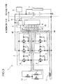
- Fig. 3 is a circuit diagram showing the charging system of the AC generator 1.
- the full-wave rectifier 2 is a bridge rectifier of circuit that includes a total of 6 power MOS FETs 8 and 9; it has three series circuits connected in parallel, each including a high side MOS FET 8 and a low side MOS FET 9 connected in series.
- An output terminal that corresponds to one of the phases of the armature winding 12 is connected to each of the three points at which a high side MOS FET 8 and a low side MOS FET 9 are connected together in series.
- each of the high side MOS FETs 8 is connected to the positive electrode of a battery 6 of the vehicle, while the source terminal of each of the low side MOS FETs 9 is connected to the negative electrode of the battery 6.
- each of the terminals of the armature winding 12 is connected to one of the input terminals of the MOS FET control device 4, so that the MOS FET control device 4 can detect the voltage at that output terminal (i.e. its phase voltage).
- load circuits 10 and 11 are provided between the gates and sources of the MOS FETs 8 and 9, and this feature is different from the case of a prior art device. These load circuits 10 and 11 will be described hereinafter.
- each of the MOS FETs 8 and 9 is controlled by the MOS FET control device 4 that is provided to the control device assembly 31.
- the reference symbols 14 and 15 are gate drive signal lines, and each of these connects a rectifier side signal terminal 40 that is provided to the full-wave rectifier 2 and a control side signal terminal 30 that is provided to the control device assembly 31.
- the MOS FET control device 4 supplies gate drive signals to the MOS FETs 8 and 9 on the basis of the phase voltages generated by the armature windings 12, thus turning the MOS FETs 8 and 9 ON and OFF.
- the AC electrical power that is output by the armature windings 12 is full wave rectified into DC electrical power, and this is supplied to the battery 6 and a load device 7.
- the load device 7 is an item of onboard auxiliary machinery mounted to the vehicle, such as a lighting system or an air conditioner or the like.
- the field control device 3 controls the field electrical power supplied to the field winding 13, according to a requested electrical power command related to the load device 7 that is sent from a vehicle side command control device 5. Due to this, the amount of AC electrical power that is output from the armature winding 12 is adjusted.
- the full-wave rectifier 2 is raised to a comparatively high temperature, due to generation of heat by the MOS FETs 8 and 9. Because of this, in order for the control device assembly 31 to avoid being affected by this heat generation, it is mounted in a separate chassis from that of the full-wave rectifier 2. For this reason, a construction is adopted in which the rectifier side signal terminals 40 of the full-wave rectifier 2 and the control side signal terminals 30 of the control device assembly 31 are connected together by the gate drive signal lines 14 and 15.
- Figs. 4 through 6 are figures showing the way in which the full-wave rectifier 2 and the control device assembly 31 are arranged.
- the full-wave rectifier 2 and the control device assembly 31 are fixed to the rear plate 36 that is fixed to the rear side of the center bracket 20.
- the rear plate 36 is cooled by the cooling water that flows in the coolant conduit 37.
- the heat that is generated by the full-wave rectifier 2 and the control device assembly 31 is dissipated to the cooling water via the rear plate 36.
- Fig. 4 is a figure showing the control device assembly 31 as seen from the side of the cover 26.
- Fig. 5 is a figure showing a portion of the full-wave rectifier 2 as seen from the side of the cover 26, and shows the structure of a module for one of the phases.
- Fig. 6 is a sectional view showing the way in which the gate drive signal lines 14 and 15 are connected between the full-wave rectifier 2 and the control device assembly 31 that are fixed upon the rear plate 36.
- the reference symbol 16 denotes a brush holder in which the brushes 28 are mounted (only one of which can be seen in the figure).
- the field control device 3 and the MOS FET control device 4 are mounted upon the same chassis as this brush holder 16. And control side signal terminals 30 for the field control device 3 and the MOS FET control device 4 are provided upon the outer surface of this chassis.
- the full-wave rectifier 2 includes an aluminum plate 35 that is fixed by bolts upon the rear plate 36, and a metal substrate 17 that is fixed by adhesive to the aluminum plate 35.
- a mold case 38 made from resin is provided upon the aluminum plate 35 so as to surround the metal substrate 17.
- Cu (copper) wiring patterns are laid out upon the metal substrate 17, over an insulating layer.
- the high side MOS FETs 8 and the low side MOS FETs 9 are mounted upon these Cu wiring patterns with solder. It should be understood that, in Fig. 5 , a configuration is shown that applies to the example whose circuit diagram is shown in Fig. 7 , in which two of each of the MOS FETs 8 and 9 are provided, connected in parallel.
- the drain terminals of the high side MOS FETs 8 are fixed by solder to a Cu pattern upon the metal substrate 17. This Cu pattern is electrically connected to the B terminal bus bars 34 by aluminum wire bonding. Furthermore, the source terminals of the low side MOS FETs 9 are fixed by solder to another Cu pattern upon the metal substrate 17. This Cu pattern is electrically connected to the aluminum plate 35 by aluminum wire bonding.
- resistors constituting load circuits 10 that are provided between the gates and the sources of the high side MOS FETs 8, and resistors constituting load circuits 11 that are provided between the gates and the sources of the low side MOS FETs 8.
- the aluminum plate 35 is connected to ground via the rear plate 36, the center bracket 20, and the engine 101.
- the source terminals of the high side MOS FETs 8 and the drain terminals of the low side MOS FETs 9 that are connected in series are connected by the lead wire terminals 32 to lead wires, to which the phase voltages from the armature windings 12 are output.
- Molding resin 39 is charged into the mold case 38 so as to cover over all of the metal substrate 17, the MOS FETs 8 and 9, the aluminum wire bonding, and so on.
- Fig. 6 is a sectional view of the full-wave rectifier 2 and the control device assembly 31 that are fixed upon the rear plate 36.
- the control side signal terminals 30 are provided upon the outer surface of the control device assembly 31, so as to be exposed.
- the rectifier side signal terminals 40 of the full-wave rectifier 2 that are electrically connected to the gate terminals of the MOS FETs 8 and 9 are provided upon the upper surface of the full-wave rectifier 2, so as to be exposed.
- these control side signal terminals 30 and rectifier side signal terminals 40 are connected together by the gate drive signal lines 14 and 15 that are made as FPCs (flexible printed circuits).
- bus bars made from Cu (copper) or Al (aluminum) for the gate drive signal lines 14 and 15.
- connection by connectors, connection by wire bonding, connection by screw fixing, or welding as the method for connecting the gate drive signal lines 14 and 15 and the rectifier side signal terminals 40 and the control side signal terminals 30.
- the MOS FET control device 4 supplies gate voltage to the gate terminal of the high side MOS FET 8 in the high voltage side series circuit to which the U phase output terminal is connected, and thus performs control so that a current flows from its source terminal in the direction of the drain terminal. Furthermore, the MOS FET control device 4 supplies gate voltage to the gate terminal of the low side MOS FET 9 in the low voltage side series circuit to which the V phase output terminal is connected, and thus perform control so than a current flows from its source terminal in the direction of its drain terminal. As a result, the battery 6 is charged up.
- the MOS FET control device 4 performs the converse control action, so that the MOS FET 8 of the high side series circuit to which the V phase output terminal is connected and the MOS FET 9 of the low side series circuit to which the U phase terminal is connected are put to ON, so that, again, the battery 6 is charged up. Similar operation is performed for the VW phase and for the WU phase, so that three phase full wave rectification operation is performed.
- the resistance value R should be set so that the time constant ⁇ becomes less than half the period of the phase voltage cycles at a rotational speed of 20,000 rpm (i.e. at this maximum demanded rotational speed).
- the resistance value R it would also be acceptable to set the resistance value R so that the current flowing in the resistor is less than some standard leak current.
- the gate voltage V g in this case, for example, the maximum permitted value for the loss may be set by setting the resistance value R while taking, within various types of MOS FET that are used in vehicle AC generators, the type whose gate voltage is the lowest as a reference.
- the time constant ⁇ is set so that ⁇ ⁇ 0.25 ms.
- the gate capacitance Cg is around 5,000 pF - 20,000 pF.
- the resistance value R is set so that R ⁇ 0.25 ms / 5,000 pF; that is, the upper limit value R max becomes equal to 50 k ⁇ .
- the lower limit value R min of the resistance value R is derived by consideration of the amount of loss reduction ⁇ W that is obtained when the rectifier elements are changed from diodes to MOS FETs. If the output current of this vehicle AC generator 1 is 120 A, and if as shown in Fig. 7 two each of the MOS FETs 8 and 9 are connected in parallel, then the effective value of the current that flows in each element is around 40 A. Moreover, if it is supposed that the ON resistance for each of the MOS FETs 8 and 9 is 3 m ⁇ , then the voltage drop when a current of 40 A flows is 0.12 V.
- the resistance value R should be set so that V g 2 /W max ( ⁇ ) ⁇ R ⁇ 50 k ⁇ . Accordingly, the resistance value R may be permitted to become quite small.
- the resistance value R is set so that R>500 ⁇ , in order for the current that flows in the load circuits 10 and 11 to be less than 10 mA.
- the lower limit value R min for the resistance value R becomes 500 ⁇ .
- the upper limit value R max is taken as being 50 k ⁇ as described above, then the final condition for the resistance value R is that it should be set so that 500 ⁇ ⁇ R ⁇ 50 k ⁇ .
- this embodiment is arranged to connect the load circuits 10 and 11 between the gates and the sources of the MOS FETs 8 and 9 that are provided to the full-wave rectifier 2 as rectifier elements, for bleeding down electric charges that may be accumulated in the gate capacitances of these MOS FETs 8 and 9 if one of the gate drive signal lines breaks. Due to this provision, even if one of the gate drive signal lines should become broken or otherwise interrupted, it becomes possible for the gate terminal of the corresponding MOS FET 8 or 9 to be brought to the same electrical potential as its source terminal, so that this MOS FET 8 or 9 goes to OFF.
- the resistance value of the resistors that constitute the load circuits 10 and 11 so that the time constant that is defined as the product of this resistance value and the gate capacitance of the MOS FETs 8 and 9 is smaller than half the period of the phase voltage cycle when this vehicular alternator is rotating at its maximum demanded rotational speed, and moreover so that the losses in the resistors when drive signals are being applied is less than the predetermined maximum permitted loss, it is possible to ensure that the MOS FETs track the ON and OFF switching commands supplied to them, while at the same time suppressing losses in the resistors to the maximum possible degree.
Landscapes
- Engineering & Computer Science (AREA)
- Power Engineering (AREA)
- Control Of Eletrric Generators (AREA)
- Rectifiers (AREA)
- Synchronous Machinery (AREA)
Applications Claiming Priority (1)
| Application Number | Priority Date | Filing Date | Title |
|---|---|---|---|
| JP2009207056A JP5133952B2 (ja) | 2009-09-08 | 2009-09-08 | 車両用交流発電機の整流装置 |
Publications (1)
| Publication Number | Publication Date |
|---|---|
| EP2293425A2 true EP2293425A2 (de) | 2011-03-09 |
Family
ID=43447828
Family Applications (1)
| Application Number | Title | Priority Date | Filing Date |
|---|---|---|---|
| EP10173229A Withdrawn EP2293425A2 (de) | 2009-09-08 | 2010-08-18 | Fahrzeugdrehstromgenerator und Gleichrichter eines Fahrzeugdrehstromgenerators |
Country Status (3)
| Country | Link |
|---|---|
| US (1) | US20110057630A1 (de) |
| EP (1) | EP2293425A2 (de) |
| JP (1) | JP5133952B2 (de) |
Families Citing this family (10)
| Publication number | Priority date | Publication date | Assignee | Title |
|---|---|---|---|---|
| KR101765937B1 (ko) * | 2011-06-30 | 2017-08-08 | 현대자동차주식회사 | 차량용 알터네이터 |
| DE102015011718A1 (de) | 2014-09-10 | 2016-03-10 | Infineon Technologies Ag | Gleichrichtervorrichtung und Anordnung von Gleichrichtern |
| US9929685B2 (en) * | 2015-06-10 | 2018-03-27 | Infineon Technologies Ag | Safety circuit and brush holder for preventing fault conditions in an alternator |
| US10033297B2 (en) | 2016-12-14 | 2018-07-24 | Infineon Technologies Ag | Rectifier device |
| US10381919B2 (en) | 2016-12-14 | 2019-08-13 | Infineon Technologies Ag | Rectifier device with safety threshold |
| US9960705B1 (en) | 2016-12-14 | 2018-05-01 | Infineon Technologies Ag | Rectifier device with stand-by detection capability |
| US10291146B2 (en) | 2017-03-30 | 2019-05-14 | Infineon Technologies Ag | Gate driver circuit for a rectifier device including a cascade of transistor stages |
| US10128736B1 (en) * | 2017-06-23 | 2018-11-13 | Infineon Technologies Ag | Rectifier device |
| JP6945500B2 (ja) * | 2018-06-11 | 2021-10-06 | 三菱電機株式会社 | 励磁装置 |
| CN111384824A (zh) * | 2020-04-26 | 2020-07-07 | 湖北神电汽车电机有限公司 | 基于主动整流二极管应用的高效汽车发电机 |
Citations (1)
| Publication number | Priority date | Publication date | Assignee | Title |
|---|---|---|---|---|
| JP2004007964A (ja) | 2002-03-29 | 2004-01-08 | Denso Corp | 車両用三相回転電機用インバータ回路装置 |
Family Cites Families (5)
| Publication number | Priority date | Publication date | Assignee | Title |
|---|---|---|---|---|
| JP3458531B2 (ja) * | 1995-06-02 | 2003-10-20 | 株式会社デンソー | 交流発電機 |
| JP3491797B2 (ja) * | 1995-12-05 | 2004-01-26 | 株式会社デンソー | 車両用発電装置 |
| US20060022355A1 (en) * | 2004-07-29 | 2006-02-02 | Takayuki Murai | Power module and electric transportation apparatus incorporating the same |
| JP4743396B2 (ja) * | 2004-07-29 | 2011-08-10 | ヤマハ発動機株式会社 | パワーモジュール、モータコントロールユニット、電動輸送機器およびパワーモジュールの製造方法 |
| US7760524B2 (en) * | 2007-10-17 | 2010-07-20 | Power Integrations, Inc. | Method and apparatus to reduce the volume required for bulk capacitance in a power supply |
-
2009
- 2009-09-08 JP JP2009207056A patent/JP5133952B2/ja not_active Expired - Fee Related
-
2010
- 2010-08-18 EP EP10173229A patent/EP2293425A2/de not_active Withdrawn
- 2010-08-20 US US12/859,959 patent/US20110057630A1/en not_active Abandoned
Patent Citations (1)
| Publication number | Priority date | Publication date | Assignee | Title |
|---|---|---|---|---|
| JP2004007964A (ja) | 2002-03-29 | 2004-01-08 | Denso Corp | 車両用三相回転電機用インバータ回路装置 |
Also Published As
| Publication number | Publication date |
|---|---|
| JP5133952B2 (ja) | 2013-01-30 |
| JP2011061928A (ja) | 2011-03-24 |
| US20110057630A1 (en) | 2011-03-10 |
Similar Documents
| Publication | Publication Date | Title |
|---|---|---|
| EP2293425A2 (de) | Fahrzeugdrehstromgenerator und Gleichrichter eines Fahrzeugdrehstromgenerators | |
| JP4754009B2 (ja) | 車両用回転電機 | |
| CN101006633B (zh) | 旋转电机 | |
| CN102668364B (zh) | 在同步整流器中避免甩负载过电压 | |
| CN103155369B (zh) | 控制装置一体型旋转电机 | |
| US9203288B2 (en) | Rotary electric machine with power converter | |
| JP2005328690A (ja) | 車両用回転電機 | |
| US20190097561A1 (en) | Inverter driver | |
| US10056752B2 (en) | Rotary electric machine for a vehicle | |
| US7196497B2 (en) | Vehicle-mounted electrical generating system in which field current of electric generator supplying power to high-voltage system is derived from supply voltage of low-voltage system | |
| CN111133672B (zh) | 交流发电机系统 | |
| US7541758B2 (en) | MOS rectifying device, driving method thereof, and motor generator and motor vehicle using thereof | |
| EP1280253A3 (de) | Spannungsregler vom externen Typ für einen Fahrzeuggenerator | |
| JP2017204953A (ja) | 回転電機ユニット | |
| JP2008005676A (ja) | 制御装置一体型回転電機 | |
| JP5297909B2 (ja) | 車両用交流発電機 | |
| US20120112608A1 (en) | Electric machine having an integrated inverter | |
| JP6277601B2 (ja) | 車両用回転電機 | |
| JP4089421B2 (ja) | 車両用交流発電機 | |
| JP2005348494A (ja) | 回転電機 | |
| JP4399439B2 (ja) | 車載型回転電機 | |
| JP6089942B2 (ja) | 車両用回転電機 | |
| JP7232788B2 (ja) | 半導体装置、パワーモジュール、インバータ装置、および電動車両 | |
| JP3055180B2 (ja) | 車両用電源装置 | |
| Robert Bosch GmbH | Alternators |
Legal Events
| Date | Code | Title | Description |
|---|---|---|---|
| PUAI | Public reference made under article 153(3) epc to a published international application that has entered the european phase |
Free format text: ORIGINAL CODE: 0009012 |
|
| 17P | Request for examination filed |
Effective date: 20101119 |
|
| AK | Designated contracting states |
Kind code of ref document: A2 Designated state(s): AL AT BE BG CH CY CZ DE DK EE ES FI FR GB GR HR HU IE IS IT LI LT LU LV MC MK MT NL NO PL PT RO SE SI SK SM TR |
|
| AX | Request for extension of the european patent |
Extension state: BA ME RS |
|
| STAA | Information on the status of an ep patent application or granted ep patent |
Free format text: STATUS: THE APPLICATION HAS BEEN WITHDRAWN |
|
| 18W | Application withdrawn |
Effective date: 20150317 |