EP2293482B1 - Procédé et dispositif de détection de signal pour un système multi-émission multiréception multi-code - Google Patents
Procédé et dispositif de détection de signal pour un système multi-émission multiréception multi-code Download PDFInfo
- Publication number
- EP2293482B1 EP2293482B1 EP09799947.8A EP09799947A EP2293482B1 EP 2293482 B1 EP2293482 B1 EP 2293482B1 EP 09799947 A EP09799947 A EP 09799947A EP 2293482 B1 EP2293482 B1 EP 2293482B1
- Authority
- EP
- European Patent Office
- Prior art keywords
- matrix
- signal
- equivalent
- channel
- unit
- Prior art date
- Legal status (The legal status is an assumption and is not a legal conclusion. Google has not performed a legal analysis and makes no representation as to the accuracy of the status listed.)
- Active
Links
Images


Classifications
-
- H—ELECTRICITY
- H04—ELECTRIC COMMUNICATION TECHNIQUE
- H04L—TRANSMISSION OF DIGITAL INFORMATION, e.g. TELEGRAPHIC COMMUNICATION
- H04L1/00—Arrangements for detecting or preventing errors in the information received
- H04L1/02—Arrangements for detecting or preventing errors in the information received by diversity reception
- H04L1/06—Arrangements for detecting or preventing errors in the information received by diversity reception using space diversity
-
- H—ELECTRICITY
- H04—ELECTRIC COMMUNICATION TECHNIQUE
- H04L—TRANSMISSION OF DIGITAL INFORMATION, e.g. TELEGRAPHIC COMMUNICATION
- H04L25/00—Baseband systems
- H04L25/02—Details ; arrangements for supplying electrical power along data transmission lines
- H04L25/0202—Channel estimation
- H04L25/024—Channel estimation channel estimation algorithms
- H04L25/0242—Channel estimation channel estimation algorithms using matrix methods
Definitions
- the present invention relates to the field of communication, and in particular, to a signal detecting method and device for a multi-codeword multi-input multi-output (MIMO) system.
- MIMO multi-codeword multi-input multi-output
- a plurality of antennas is installed in a transmitting end and a receiving end of a MIMO system.
- the transmitting end transmits a plurality of independent signals through different transmitting antennas by using space division multiplexing technology
- the receiving end receives the signals from different receiving antennas and obtains the signal transmitted from the transmitting end from the received signals.
- the transmitting end may use a mono-codeword or multi-codeword space division multiplexing manner to transmit signals.
- the mono-codeword manner multiple antenna signals transmitted from the transmitting end are code-modulated using the same code modulation manner; and in the multi-codeword manner, the multiple antenna signals transmitted from the transmitting end are code-modulated using two or more code modulation manners.
- a receiving end of a multi-codeword MIMO system detects the signal transmitted from the transmitting end from the received signals mainly through three methods: Maximum Likelihood (ML), Zero-Forcing (ZF) and Minimum Mean-Squared Error (MMSE).
- ML Maximum Likelihood
- ZF Zero-Forcing
- MMSE Minimum Mean-Squared Error
- the detecting principle of the ML detecting method is as follows: a channel matrix is estimated, and a probably received signal vector is obtained according to the estimated channel matrix and the known signal vector probably transmitted from the transmitting end; and an actually received signal vector is compared with the probably received signal vector, a signal which is closest to the signal in the probably received signal vector is obtained from the actually received signal vector, and the signal is used as the detected signal transmitted from the transmitting end.
- the error-between the signal detected through the ML detecting method and the signal transmitted from the transmitting end is small.
- the number of calculations of the ML detecting method is large when the number of the transmitting antennas and the receiving antennas is large, thus causing complex implementation of the ML detecting method.
- the detecting principle of the MMSE detecting method is basically the same as the detecting principle of the ZF detecting method, and the difference lies in that when a channel equalization matrix is calculated through the MMSE detecting method, the estimation of the channel noise power is added, and the effect of noise and interference is taken into consideration.
- a channel estimator estimates a channel impulse response for a radio channel corresponding to a predetermined plurality of regularly spaced direction-of-arrival (DOA) values.
- a data estimator estimates the received data using a received signal and a system matrix comprising an allocated spreading code and the channel impulse response.
- a quantizer quantizes the estimated data.
- An interference and noise calculator calculates noise vectors at the respective antenna elements by removing from the received signal an influence of the quantized data to which the system matrix is applied, calculates an estimated noise matrix at the plurality of antenna elements, calculates interference power by auto-correlating the estimated noise matrix, and calculates noise and interference power based on the interference power.
- the present invention is directed to a signal detecting method and device for a multi-codeword MIMO system, which is easy to implement, and can reduce the error between the signal obtained through detection and the signal actually transmitted from the transmitting end.
- Another aspect of the present invention provides a signal detecting device for a multi-codeword MIMO system, which includes:
- the equivalent channel matrix generating unit (6031) is specifically adapted to:
- the signal detecting method and device for a multi-codeword MIMO system since the channel matrix is corrected, the problem in the prior art that the noise has a great effect on the signal detected by the receiving end of the multi-codeword MIMO system due to poor channel quality (severely ill-conditioned channel matrix) is solved; since the equivalent detecting signal obtained through detection is quantized, the quality of the equivalent detecting signal after quantization is improved, so that the error between the signal transmitted from the transmitting end that is generated according to the equivalent quantized detecting signal obtained after quantization and the signal actually transmitted from the transmitting end is reduced, thereby solving the problem in the prior art that the error between the detecting signal obtained through detection and the signal actually transmitted from the transmitting end is large. Further, the technical solutions of the present invention are easy to implement.
- the present invention provides a signal detecting method and device for a multi-codeword MIMO system.
- the transmitting end of the multi-codeword MIMO system can transmit p code streams and use p modulation manners to perform modulation.
- the transmitting end and the receiving end of the multi-codeword MIMO system communicate with each other through a channel as shown in FIG. 2 , in which, the channel is a narrowband channel.
- the receiving end detects the received signal by using a signal detecting method for a multi-codeword MIMO system according to an embodiment of the present invention, which includes the following blocks.
- a complex number signal received by the receiving end is converted into a real number signal.
- the complex number signal Y C is converted into a real number signal Y.
- a p v p
- the element contained in the n is an independent real Gaussian random variable whose mean is zero and variance is ⁇ 2 2 .
- channel estimation is performed to obtain a channel matrix H.
- the channel matrix H is corrected to obtain an equivalent corrected matrix H .
- the channel matrix H is corrected through a lattice reduction (LR) algorithm in the Block 303. As shown in FIG. 4 , the following blocks are included.
- LR lattice reduction
- an equivalent channel matrix H 0 is generated according to the channel matrix H, which includes the following steps.
- a transformation matrix T is generated according to the generated equivalent channel matrix H 0 .
- the transformation matrix T is generated according to the equivalent channel matrix H 0 through an LLL (Lenstra-Lenstra-Lovász) algorithm in the Block 402.
- the equivalent channel matrix H 0 is corrected by using the transformation matrix T, so as to obtain an equivalent corrected matrix H .
- an equivalent detecting signal z is generated according to the equivalent corrected matrix H and the real number signal Y obtained through conversion.
- the equivalent detecting signal z may be generated through two methods in the Block 304: one method is that the equivalent detecting signal z is generated by using a ZF algorithm; the other method is that the equivalent detecting signal z is generated by using an MMSE algorithm.
- one method is that the equivalent detecting signal z is generated by using a ZF algorithm; the other method is that the equivalent detecting signal z is generated by using an MMSE algorithm.
- the equivalent detecting signal z is generated by using a ZF algorithm.
- the method may include the following blocks.
- an equivalent detecting signal z is generated according to the channel equalization matrix G and the real number signal Y obtained through conversion.
- Second method the equivalent detecting signal z is generated by using an MMSE algorithm.
- the steps of this method are basically the same as the first method, and the difference lies in that when this method is used, a noise power signal ⁇ n 2 and the power of the real number signal Y obtained in the Block 301 ⁇ n 2 need to be obtained, and at this time, a channel equalization matrix G is generated according to the equivalent corrected matrix H , the noise power signal ⁇ n 2 , and the power ⁇ x 2 of the real number signal Y.
- G ⁇ H ⁇ T ⁇ H ⁇ + ⁇ n 2 ⁇ s 2 ⁇ I 2 ⁇ N ⁇ 2 ⁇ N - 1 ⁇ H ⁇ T
- the equivalent detecting signal z is quantized to obtain an equivalent quantized detecting signal z .
- T and s are integers, so T -1 s is also an integer.
- a signal X transmitted from the transmitting end is generated according to the equivalent quantized detecting signal z .
- the signal detecting method for a multi-codeword MIMO system since the channel matrix is corrected, the problem in the prior art that the noise has a great effect on the signal detected by the receiving end of the multi-codeword MIMO system due to poor channel quality (severely ill-conditioned channel matrix) is solved; since the equivalent detecting signal obtained through detection is quantized, the quality of the equivalent detecting signal after quantization is improved, so that the error between the signal transmitted from the transmitting end that is generated according to the equivalent quantized detecting signal obtained after quantization and the signal actually transmitted from the transmitting end is reduced, thereby solving the problem in the prior art that the error between the detecting signal obtained through detection and the signal actually transmitted from the transmitting end is large. Further, the technical solution of the present invention is easy to implement.
- an embodiment of the present invention further provides a signal detecting device for a multi-codeword MIMO system, which includes:
- the channel matrix correcting unit 603 may include:
- the equivalent detecting signal generating unit 604 may include:
- the signal detecting device for a multi-codeword MIMO system may further include:
- the signal detecting device for a multi-codeword MIMO system may be used in a signal receiving device of a multi-codeword MIMO system.
- the signal detecting device for a multi-codeword MIMO system since the channel matrix is corrected, the problem in the prior art that the noise has a great effect on the signal detected by the receiving end of the multi-codeword MIMO system due to poor channel quality (severely ill-conditioned channel matrix) is solved; since the equivalent detecting signal obtained through detection is quantized, the quality of the equivalent detecting signal after quantization is improved, so that the error between the signal transmitted from the transmitting end that is generated according to the equivalent quantized detecting signal obtained after quantization and the signal actually transmitted from the transmitting end is reduced, thereby solving the problem in the prior art that the error between the detecting signal obtained through detection and the signal actually transmitted from the transmitting end is large. Further, the technical solution of the present invention is easy to implement.
- FIG. 8 , FIG. 9 and FIG. 10 respectively show the BER performance of the detecting signals obtained through the technical solutions of the present invention and the ML, ZF and MMSE algorithms provided by the prior art. It can be known through FIG. 8 , FIG. 9 and FIG. 10 that, compared with the ZF algorithm and MMSE algorithm in the prior art, the technical solutions of the present invention reduce the error between the detecting signal obtained through detection and the signal transmitted from the transmitting end.
- the complexity of the ML algorithm in the prior art is relevant to the parameters such as the number M of the transmitting antennas, the number N of the receiving antennas and the modulation manner 2 Q m -QAM used by the mth antenna.
- the ML algorithm mainly focuses on obtaining a probably received signal matrix and comparing an actually received signal matrix with the probably received signal matrix.
- the ML algorithm is complex to implement, especially when the number of the antennas of the transmitting end and the receiving end is large.
- the complexity of the technical solutions of the present invention is merely relevant to the number M of the transmitting antennas and the number N of the receiving antennas.
- the algorithm in the technical solutions of the present invention mainly focuses on the steps of correcting a channel matrix, that is, the step of correcting a channel matrix through an LR algorithm.
- the magnitude of the number of the real number multiplication and addition of the step is O ( KM 3 ) , in which, K is in the range of 10 ⁇ 10 2 .
- the technical solutions of the present invention are easier to implement.
- the program may be stored in a computer readable storage medium, such as a Read Only Memory (ROM), a Random Access Memory (RAM), a magnetic disk or an optical disk.
- ROM Read Only Memory
- RAM Random Access Memory
Landscapes
- Engineering & Computer Science (AREA)
- Computer Networks & Wireless Communication (AREA)
- Signal Processing (AREA)
- Physics & Mathematics (AREA)
- Mathematical Physics (AREA)
- Power Engineering (AREA)
- Radio Transmission System (AREA)
Claims (8)
- Procédé de détection de signaux pour un système à entrées multiples et sorties multiples (MIMO) à mots de code multiples, consistant à :- convertir (301) un signal de nombre complexe reçu en un signal de nombre réel Y ;- effectuer (302) une estimation de canal afin d'obtenir une matrice de canal H;- corriger (303) la matrice de canal H afin d'obtenir une matrice corrigée équivalente
H ;- générer (304) un signal de détection équivalent Z en fonction de la matrice corrigée équivalenteH et du signal de nombre réel Y obtenu par la conversion ;- quantifier (305) le signal de détection équivalent Z afin d'obtenir un signal de détection quantifié équivalentz ; et- générer (306) un signal X transmis depuis une extrémité de transmission en fonction du signal de détection quantifié équivalentcaractérisé en ce que :z ;- la correction (303) de la matrice de canal H afin d'obtenir la matrice corrigée équivalenteH consiste à :- générer (401) une matrice de canal équivalente H0 en fonction de la matrice de canal H ;- générer (402) une matrice de transformation T en fonction de la matrice de canal équivalente générée H0 ; et- corriger (403) la matrice de canal équivalente H0 en utilisant la matrice de transformation T de manière à obtenir la matrice corrigée équivalenteH =H0T ;- dans lequel la génération (401) de la matrice de canal équivalente H0 en fonction de la matrice de canal H consiste à :- transformer une fonction de modèle de canal Y=HX+n obtenue après que le signal de nombre complexe reçu a été converti en signal de nombre réel Y, de manière à obtenir une fonction de modèle de canal Y=H(As+b)+n après transformation ;- dans laquelle A est une matrice diagonale 2Mx2M dont l'élément diagonal est diag(A)=[a1,a2, ..., aM,a1,a2, ...,aM], et lorsqu'un signal xm transmis sur une mème antenne de l'extrémité de transmission est modulé en utilisant une pème manière de modulation 2Qp - QAM, am=αp, et - b est une matrice 2Mx1, b=[b1,b2, ..., bM,b1,b2, ..., bM]T, et lorsque le signal xm transmis sur la mème antenne de l'extrémité de transmission est modulé en utilisant la pème manière de modulation 2 Q
p - QAM, bm=βp , et - s est une matrice 2M×1 comprenant des éléments entiers, s=[s1,s2, ..., sM,s1,s2, ..., sM]T, et lorsque le signal xm transmis sur la mème antenne de l'extrémité de transmission est modulé en utilisant la pème manière de modulation 2 Q
p - QAM,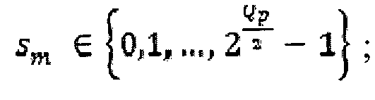 - extraire A de la fonction de modèle de canal Y=H(As+b)+n obtenue après transformation de manière à obtenir la matrice de canal équivalente H0=HA ;- dans lequel le signal X = AT
z . - Procédé de détection de signaux pour un système MIMO à mots de code multiples selon la revendication 1, dans lequel la génération (304) du signal de détection équivalent en fonction de la matrice corrigée équivalente
H et du signal de nombre réel obtenu par conversion consiste à :- générer (501) une matrice d'égalisation de canaux en fonction de la matrice corrigée équivalenteH , où le produit de la matrice d'égalisation de canaux et de la matrice corrigée équivalenteH est une matrice unitaire ; et- générer (502) un signal de détection équivalent en fonction de la matrice d'égalisation de canaux et du signal de nombre réel obtenu par la conversion. - Procédé de détection de signaux pour un système MIMO à mots de code multiples selon la revendication 2, dans lequel la génération (501) de la matrice d'égalisation de canaux en fonction de la matrice corrigée équivalente
H , où le produit de la matrice d'égalisation de canaux et de la matrice corrigée équivalenteH est une matrice unitaire, consiste à :- générer une matrice d'égalisation de canauxG en fonction de la matrice corrigée équivalenteH et d'une formuleG = (H TH )-1H T oùGH = I, et I est une matrice unitaire. - Procédé de détection de signaux pour un système MIMO à mots de code multiples selon la revendication 2, dans lequel, avant de générer la matrice d'égalisation de canaux en fonction de la matrice corrigée équivalente
H , le procédé de détection de signaux consiste en outre à :- obtenir un signal de puissance de bruit ; et- générer la matrice d'égalisation de canaux en fonction de la matrice corrigée équivalenteH consiste à générer une matrice d'égalisation de canaux en fonction de la matrice corrigée équivalenteH et du signal de puissance de bruit. - Procédé de détection de signaux pour un système MIMO à mots de code multiples selon la revendication 4, dans lequel la génération de la matrice d'égalisation de canaux en fonction de la matrice corrigée équivalente
H et du signal de puissance de bruit consiste à :- générer une matrice d'égalisation de canauxG en fonction de la matrice corrigée équivalenteH , du signal de puissance de bruit


- Dispositif de détection de signaux pour un système à entrées multiples et sorties multiples (MIMO) à mots de code multiples, comprenant :- une unité de conversion de signaux (601) conçue pour convertir un signal de nombre complexe reçu en un signal de nombre réel Y ;- une unité d'estimation de canal (602) conçue pour effectuer une estimation de canal afin d'obtenir une matrice de canal H ;- une unité de correction de matrice de canal (603) conçue pour corriger la matrice de canal H obtenue par l'unité d'estimation de canal (602) afin d'obtenir une matrice corrigée équivalente
H ;- une unité de génération de signal de détection équivalent (604) conçue pour générer un signal de détection équivalent Z en fonction de la matrice corrigée équivalenteH obtenue par l'unité de correction de matrice de canal (603), et du signal de nombre réel Y généré par l'unité de conversion de signaux (601) ;- une unité de quantification de signal de détection équivalent (605) conçue pour quantifier le signal de détection équivalent Z généré par l'unité de génération de signal de détection équivalent (604) afin d'obtenir un signal de détection quantifié équivalentz ; et- une unité de génération de signal transmis depuis une extrémité de transmission (606) conçue pour générer un signal X transmis depuis une extrémité de transmission en fonction du signal de détection quantifié équivalentz obtenu par l'unité de quantification de signal de détection équivalent ;- caractérisé en ce que :- l'unité de correction de matrice de canal (603) comprend :- une unité de génération de matrice de canal équivalente (6031) conçue pour générer une matrice de canal équivalente H0 en fonction de la matrice de canal H obtenue par l'unité d'estimation de canal ;- une unité de génération de matrice de transformation (6032) conçue pour générer une matrice de transformation T en fonction de la matrice de canal équivalente H0 obtenue par l'unité de génération de matrice de canal équivalente ; et- une unité de correction (6033) conçue pour corriger la matrice de canal équivalente H0 générée par l'unité de génération de matrice de canal équivalente (6031) en utilisant la matrice de transformation T générée par l'unité de génération de matrice de transformation (6032) de manière à obtenir la matrice corrigée équivalenteH = H0T ;- dans lequel l'unité de génération de matrice de canal équivalent (6031) est spécifiquement conçue pour :- transformer une fonction de modèle de canal Y=HX+n obtenue après que le signal de nombre complexe reçu a été converti en signal de nombre réel Y, de manière à obtenir une fonction de modèle de canal Y=H(As+b)+n après transformation ;- dans laquelle A est une matrice diagonale 2Mx2M dont l'élément diagonal est diag(A)=[a1,a2, ..., aM,a1,a2, ...,aM], et lorsqu'un signal xm transmis sur une mème antenne de l'extrémité de transmission est modulé en utilisant une pème manière de modulation 2 Qp - QAM, am=αp, et - b est une matrice 2M×1, b=[b1,b2, ..., bM,b1,b2, ..., bM]T, et lorsque le signal xm transmis sur la mème antenne de l'extrémité de transmission est modulé en utilisant la pème manière de modulation 2 Q
p - QAM, bm=βp, et - s est une matrice 2M×1 comprenant des éléments entiers, s=[s1,s2, ..., sM,s1,s2, ..., sM]T, et lorsque le signal xm transmis sur la mème antenne de l'extrémité de transmission est modulé en utilisant la pème manière de modulation 2 Q
p - QAM, - extraire A de la fonction de modèle de canal Y=H(As+b)+n obtenue après transformation de manière à obtenir la matrice de canal équivalente H0=HA ;- dans lequel le signal X = AT
z . - Dispositif de détection de signaux pour un système MIMO à mots de code multiples selon la revendication 6, dans lequel l'unité de génération de signal de détection équivalent (604) comprend :- une unité de génération de matrice d'égalisation de canaux (6041) conçue pour générer une matrice d'égalisation de canaux en fonction de la matrice corrigée équivalente
H obtenue par l'unité de correction de matrice de canal (603), où le produit de la matrice d'égalisation de canaux et de la matrice corrigée équivalenteH est une matrice unitaire ; et- une unité de génération (6042) conçue pour générer un signal de détection équivalent en fonction de la matrice d'égalisation de canaux générée par l'unité de génération de matrice d'égalisation de canaux (6041) et du signal de nombre réel obtenu par l'unité de conversion de signaux (601). - Dispositif de détection de signaux pour un système MIMO à mots de code multiples selon la revendication 7, comprenant en outre une unité d'obtention de puissance de signal de bruit (607) conçue pour obtenir un signal de puissance de bruit, dans lequel l'unité de génération de matrice d'égalisation de canaux (6041) est une seconde unité de génération de matrice d'égalisation de canaux conçue pour générer une matrice d'égalisation de canaux en fonction de la matrice corrigée équivalente
H obtenue par l'unité de correction de matrice de canal (603), et du signal de puissance de bruit obtenu par l'unité d'obtention de puissance de signal de bruit (607).
Applications Claiming Priority (2)
| Application Number | Priority Date | Filing Date | Title |
|---|---|---|---|
| CN2008101344294A CN101330361B (zh) | 2008-07-23 | 2008-07-23 | 多码字多发多收系统的信号检测方法和装置 |
| PCT/CN2009/071298 WO2010009631A1 (fr) | 2008-07-23 | 2009-04-16 | Procédé et dispositif de détection de signal pour un système multi-émission multiréception multi-code |
Publications (3)
| Publication Number | Publication Date |
|---|---|
| EP2293482A1 EP2293482A1 (fr) | 2011-03-09 |
| EP2293482A4 EP2293482A4 (fr) | 2011-12-21 |
| EP2293482B1 true EP2293482B1 (fr) | 2013-06-12 |
Family
ID=40205981
Family Applications (1)
| Application Number | Title | Priority Date | Filing Date |
|---|---|---|---|
| EP09799947.8A Active EP2293482B1 (fr) | 2008-07-23 | 2009-04-16 | Procédé et dispositif de détection de signal pour un système multi-émission multiréception multi-code |
Country Status (4)
| Country | Link |
|---|---|
| US (1) | US8300677B2 (fr) |
| EP (1) | EP2293482B1 (fr) |
| CN (1) | CN101330361B (fr) |
| WO (1) | WO2010009631A1 (fr) |
Families Citing this family (6)
| Publication number | Priority date | Publication date | Assignee | Title |
|---|---|---|---|---|
| CN101330361B (zh) * | 2008-07-23 | 2011-08-10 | 华为技术有限公司 | 多码字多发多收系统的信号检测方法和装置 |
| US8365032B2 (en) * | 2009-11-23 | 2013-01-29 | Futurewei Technologies, Inc. | System and method for multiple input, multiple output (MIMO) communications |
| CN102257778B (zh) * | 2011-06-07 | 2014-12-03 | 华为技术有限公司 | 信道质量估计方法、装置及无线接收机 |
| JP2016082311A (ja) * | 2014-10-10 | 2016-05-16 | 富士通株式会社 | 受信装置および等化処理方法 |
| CN104702382B (zh) * | 2015-03-31 | 2017-09-01 | 潍坊学院 | 空间调制系统中多圈apm数字调制星座的遍历产生方法 |
| US11309992B2 (en) * | 2018-07-17 | 2022-04-19 | Qualcomm Incorporated | Using lattice reduction for reduced decoder complexity |
Family Cites Families (11)
| Publication number | Priority date | Publication date | Assignee | Title |
|---|---|---|---|---|
| CN1146170C (zh) * | 2000-11-27 | 2004-04-14 | 华为技术有限公司 | 一种多用户扩频通信系统联合检测的改进方法 |
| KR100580843B1 (ko) * | 2003-12-22 | 2006-05-16 | 한국전자통신연구원 | V―blast에서 채널전달함수행렬 처리장치 및 그의처리방법 |
| US7489746B1 (en) * | 2004-04-22 | 2009-02-10 | Qualcomm, Inc. | MIMO receiver using maximum likelihood detector in combination with QR decomposition |
| KR100663525B1 (ko) * | 2004-06-10 | 2007-02-28 | 삼성전자주식회사 | 공간-시간 빔 형성을 위한 간섭전력 측정 장치 및 방법 |
| US7616699B2 (en) * | 2005-04-12 | 2009-11-10 | Samsung Electronics Co., Ltd. | Method of soft bit metric calculation with direct matrix inversion MIMO detection |
| US8385433B2 (en) * | 2005-10-27 | 2013-02-26 | Qualcomm Incorporated | Linear precoding for spatially correlated channels |
| CN101102295A (zh) * | 2006-07-07 | 2008-01-09 | 大唐移动通信设备有限公司 | 空间分集复用的方法以及多输入输出通信系统 |
| JP5214124B2 (ja) * | 2006-08-17 | 2013-06-19 | 三星電子株式会社 | 通信システム、通信装置、尤度計算方法、及びプログラム |
| US7974334B2 (en) * | 2007-01-30 | 2011-07-05 | Texas Instruments Incorporated | Systems and methods for hybrid-MIMO equalization |
| KR101369226B1 (ko) * | 2007-05-25 | 2014-03-06 | 삼성전자주식회사 | Stbc 신호의 복호화 장치 및 그 제어방법 |
| CN101330361B (zh) * | 2008-07-23 | 2011-08-10 | 华为技术有限公司 | 多码字多发多收系统的信号检测方法和装置 |
-
2008
- 2008-07-23 CN CN2008101344294A patent/CN101330361B/zh not_active Expired - Fee Related
-
2009
- 2009-04-16 WO PCT/CN2009/071298 patent/WO2010009631A1/fr not_active Ceased
- 2009-04-16 EP EP09799947.8A patent/EP2293482B1/fr active Active
-
2010
- 2010-12-30 US US12/981,878 patent/US8300677B2/en active Active
Also Published As
| Publication number | Publication date |
|---|---|
| CN101330361A (zh) | 2008-12-24 |
| WO2010009631A1 (fr) | 2010-01-28 |
| EP2293482A1 (fr) | 2011-03-09 |
| EP2293482A4 (fr) | 2011-12-21 |
| CN101330361B (zh) | 2011-08-10 |
| US20110142117A1 (en) | 2011-06-16 |
| US8300677B2 (en) | 2012-10-30 |
Similar Documents
| Publication | Publication Date | Title |
|---|---|---|
| US8649457B2 (en) | Precoding process for a transmitter of a MU-MIMO communication system | |
| EP2412117B1 (fr) | Répertoires adaptatifs de précodage pour communications sans fil | |
| EP1394963A2 (fr) | Dispositif et procédé d'émission et de réception de signaux utilisant plusieurs antennes | |
| CN103763222B (zh) | 一种mimo信号盲检测中的信道模糊度去除方法 | |
| EP2293482B1 (fr) | Procédé et dispositif de détection de signal pour un système multi-émission multiréception multi-code | |
| CN110417515B (zh) | 一种基于离散迭代估计的大规模mimo信号检测方法 | |
| CN107276933B (zh) | 用于上行多用户mimo系统中基于二阶统计量的信道估计方法 | |
| US8811215B2 (en) | Apparatus and method for detecting signal in spatial multiplexing system | |
| KR101092686B1 (ko) | 직교 주파수 분할 다중 접속 기반 다중안테나 무선 시스템에서 송신 빔포밍 방법 및 장치 | |
| EP2491670B1 (fr) | Système et procédé relatifs à des communications à entrées multiples et à sorties multiples (mimo) | |
| CN102752037B (zh) | 一种延时反馈下多天线中继预编码的鲁棒构造方法 | |
| US8868009B2 (en) | Method and system for multi-beam forming based on joint transceiver information | |
| CN101834693B (zh) | 一种多输入多输出信号检测方法、装置及系统 | |
| KR20070092872A (ko) | 다중 입력 다중 출력 방식을 사용하는 통신 시스템에서신호 검파 장치 및 방법 | |
| JP7264260B2 (ja) | 無線通信システム、無線通信方法、送信局装置および受信局装置 | |
| KR101327486B1 (ko) | 다중 입출력 무선통신 시스템에서 최대 우도 검출을 위한코드북 선택 장치 및 방법 | |
| US9231678B2 (en) | Method and apparatus for precoding in a two transmit antenna closed-loop MIMO fixed wireless backhaul network | |
| CN102055691A (zh) | 波束成形权值的估计处理方法和基站 | |
| CN101640649B (zh) | 信道预测时确定信道预测系数的方法、装置及信道预测器 | |
| KR20090002706A (ko) | 다중 입출력 무선통신 시스템에서 스트림별 유효 신호대잡음비 생성 장치 및 방법 | |
| KR101048442B1 (ko) | 다중 입출력 무선통신 시스템에서 스트림별 유효 신호대 잡음비 생성 장치 및 방법 | |
| EP1768295B1 (fr) | Système et procédé d'émission/réception d'un signal dans un système de communication mobile à entrées et à sorties multiples | |
| CN115865581B (zh) | 基于主成分分析的人工噪声消除方法 | |
| US10447504B1 (en) | Quantized detection in uplink MIMO with oversampling | |
| EP2309659A1 (fr) | Procédé de calcul de l'indicateur de qualité de canal dans un système de communication sans fil à entrées et sorties multiples à multiplexage spatial à l'aide de la détection linéaire |
Legal Events
| Date | Code | Title | Description |
|---|---|---|---|
| PUAI | Public reference made under article 153(3) epc to a published international application that has entered the european phase |
Free format text: ORIGINAL CODE: 0009012 |
|
| 17P | Request for examination filed |
Effective date: 20110117 |
|
| AK | Designated contracting states |
Kind code of ref document: A1 Designated state(s): AT BE BG CH CY CZ DE DK EE ES FI FR GB GR HR HU IE IS IT LI LT LU LV MC MK MT NL NO PL PT RO SE SI SK TR |
|
| AX | Request for extension of the european patent |
Extension state: AL BA RS |
|
| DAX | Request for extension of the european patent (deleted) | ||
| A4 | Supplementary search report drawn up and despatched |
Effective date: 20111118 |
|
| RIC1 | Information provided on ipc code assigned before grant |
Ipc: H04L 25/02 20060101ALI20111114BHEP Ipc: H04L 1/06 20060101AFI20111114BHEP |
|
| 17Q | First examination report despatched |
Effective date: 20120430 |
|
| GRAP | Despatch of communication of intention to grant a patent |
Free format text: ORIGINAL CODE: EPIDOSNIGR1 |
|
| GRAS | Grant fee paid |
Free format text: ORIGINAL CODE: EPIDOSNIGR3 |
|
| GRAA | (expected) grant |
Free format text: ORIGINAL CODE: 0009210 |
|
| AK | Designated contracting states |
Kind code of ref document: B1 Designated state(s): AT BE BG CH CY CZ DE DK EE ES FI FR GB GR HR HU IE IS IT LI LT LU LV MC MK MT NL NO PL PT RO SE SI SK TR |
|
| REG | Reference to a national code |
Ref country code: GB Ref legal event code: FG4D |
|
| REG | Reference to a national code |
Ref country code: CH Ref legal event code: EP |
|
| REG | Reference to a national code |
Ref country code: AT Ref legal event code: REF Ref document number: 617032 Country of ref document: AT Kind code of ref document: T Effective date: 20130615 |
|
| REG | Reference to a national code |
Ref country code: IE Ref legal event code: FG4D |
|
| REG | Reference to a national code |
Ref country code: DE Ref legal event code: R096 Ref document number: 602009016427 Country of ref document: DE Effective date: 20130808 |
|
| PG25 | Lapsed in a contracting state [announced via postgrant information from national office to epo] |
Ref country code: SI Free format text: LAPSE BECAUSE OF FAILURE TO SUBMIT A TRANSLATION OF THE DESCRIPTION OR TO PAY THE FEE WITHIN THE PRESCRIBED TIME-LIMIT Effective date: 20130612 Ref country code: FI Free format text: LAPSE BECAUSE OF FAILURE TO SUBMIT A TRANSLATION OF THE DESCRIPTION OR TO PAY THE FEE WITHIN THE PRESCRIBED TIME-LIMIT Effective date: 20130612 Ref country code: GR Free format text: LAPSE BECAUSE OF FAILURE TO SUBMIT A TRANSLATION OF THE DESCRIPTION OR TO PAY THE FEE WITHIN THE PRESCRIBED TIME-LIMIT Effective date: 20130913 Ref country code: SE Free format text: LAPSE BECAUSE OF FAILURE TO SUBMIT A TRANSLATION OF THE DESCRIPTION OR TO PAY THE FEE WITHIN THE PRESCRIBED TIME-LIMIT Effective date: 20130612 Ref country code: NO Free format text: LAPSE BECAUSE OF FAILURE TO SUBMIT A TRANSLATION OF THE DESCRIPTION OR TO PAY THE FEE WITHIN THE PRESCRIBED TIME-LIMIT Effective date: 20130912 Ref country code: LT Free format text: LAPSE BECAUSE OF FAILURE TO SUBMIT A TRANSLATION OF THE DESCRIPTION OR TO PAY THE FEE WITHIN THE PRESCRIBED TIME-LIMIT Effective date: 20130612 Ref country code: ES Free format text: LAPSE BECAUSE OF FAILURE TO SUBMIT A TRANSLATION OF THE DESCRIPTION OR TO PAY THE FEE WITHIN THE PRESCRIBED TIME-LIMIT Effective date: 20130923 |
|
| REG | Reference to a national code |
Ref country code: AT Ref legal event code: MK05 Ref document number: 617032 Country of ref document: AT Kind code of ref document: T Effective date: 20130612 |
|
| REG | Reference to a national code |
Ref country code: NL Ref legal event code: VDEP Effective date: 20130612 |
|
| REG | Reference to a national code |
Ref country code: LT Ref legal event code: MG4D |
|
| PG25 | Lapsed in a contracting state [announced via postgrant information from national office to epo] |
Ref country code: HR Free format text: LAPSE BECAUSE OF FAILURE TO SUBMIT A TRANSLATION OF THE DESCRIPTION OR TO PAY THE FEE WITHIN THE PRESCRIBED TIME-LIMIT Effective date: 20130612 Ref country code: BG Free format text: LAPSE BECAUSE OF FAILURE TO SUBMIT A TRANSLATION OF THE DESCRIPTION OR TO PAY THE FEE WITHIN THE PRESCRIBED TIME-LIMIT Effective date: 20130912 |
|
| PG25 | Lapsed in a contracting state [announced via postgrant information from national office to epo] |
Ref country code: LV Free format text: LAPSE BECAUSE OF FAILURE TO SUBMIT A TRANSLATION OF THE DESCRIPTION OR TO PAY THE FEE WITHIN THE PRESCRIBED TIME-LIMIT Effective date: 20130612 |
|
| PG25 | Lapsed in a contracting state [announced via postgrant information from national office to epo] |
Ref country code: CZ Free format text: LAPSE BECAUSE OF FAILURE TO SUBMIT A TRANSLATION OF THE DESCRIPTION OR TO PAY THE FEE WITHIN THE PRESCRIBED TIME-LIMIT Effective date: 20130612 Ref country code: SK Free format text: LAPSE BECAUSE OF FAILURE TO SUBMIT A TRANSLATION OF THE DESCRIPTION OR TO PAY THE FEE WITHIN THE PRESCRIBED TIME-LIMIT Effective date: 20130612 Ref country code: AT Free format text: LAPSE BECAUSE OF FAILURE TO SUBMIT A TRANSLATION OF THE DESCRIPTION OR TO PAY THE FEE WITHIN THE PRESCRIBED TIME-LIMIT Effective date: 20130612 Ref country code: EE Free format text: LAPSE BECAUSE OF FAILURE TO SUBMIT A TRANSLATION OF THE DESCRIPTION OR TO PAY THE FEE WITHIN THE PRESCRIBED TIME-LIMIT Effective date: 20130612 Ref country code: IS Free format text: LAPSE BECAUSE OF FAILURE TO SUBMIT A TRANSLATION OF THE DESCRIPTION OR TO PAY THE FEE WITHIN THE PRESCRIBED TIME-LIMIT Effective date: 20131012 Ref country code: PT Free format text: LAPSE BECAUSE OF FAILURE TO SUBMIT A TRANSLATION OF THE DESCRIPTION OR TO PAY THE FEE WITHIN THE PRESCRIBED TIME-LIMIT Effective date: 20131014 Ref country code: BE Free format text: LAPSE BECAUSE OF FAILURE TO SUBMIT A TRANSLATION OF THE DESCRIPTION OR TO PAY THE FEE WITHIN THE PRESCRIBED TIME-LIMIT Effective date: 20130612 |
|
| PG25 | Lapsed in a contracting state [announced via postgrant information from national office to epo] |
Ref country code: PL Free format text: LAPSE BECAUSE OF FAILURE TO SUBMIT A TRANSLATION OF THE DESCRIPTION OR TO PAY THE FEE WITHIN THE PRESCRIBED TIME-LIMIT Effective date: 20130612 Ref country code: NL Free format text: LAPSE BECAUSE OF FAILURE TO SUBMIT A TRANSLATION OF THE DESCRIPTION OR TO PAY THE FEE WITHIN THE PRESCRIBED TIME-LIMIT Effective date: 20130612 Ref country code: RO Free format text: LAPSE BECAUSE OF FAILURE TO SUBMIT A TRANSLATION OF THE DESCRIPTION OR TO PAY THE FEE WITHIN THE PRESCRIBED TIME-LIMIT Effective date: 20130612 |
|
| PLBE | No opposition filed within time limit |
Free format text: ORIGINAL CODE: 0009261 |
|
| STAA | Information on the status of an ep patent application or granted ep patent |
Free format text: STATUS: NO OPPOSITION FILED WITHIN TIME LIMIT |
|
| PG25 | Lapsed in a contracting state [announced via postgrant information from national office to epo] |
Ref country code: DK Free format text: LAPSE BECAUSE OF FAILURE TO SUBMIT A TRANSLATION OF THE DESCRIPTION OR TO PAY THE FEE WITHIN THE PRESCRIBED TIME-LIMIT Effective date: 20130612 |
|
| 26N | No opposition filed |
Effective date: 20140313 |
|
| PG25 | Lapsed in a contracting state [announced via postgrant information from national office to epo] |
Ref country code: IT Free format text: LAPSE BECAUSE OF FAILURE TO SUBMIT A TRANSLATION OF THE DESCRIPTION OR TO PAY THE FEE WITHIN THE PRESCRIBED TIME-LIMIT Effective date: 20130612 |
|
| REG | Reference to a national code |
Ref country code: DE Ref legal event code: R097 Ref document number: 602009016427 Country of ref document: DE Effective date: 20140313 |
|
| PG25 | Lapsed in a contracting state [announced via postgrant information from national office to epo] |
Ref country code: LU Free format text: LAPSE BECAUSE OF FAILURE TO SUBMIT A TRANSLATION OF THE DESCRIPTION OR TO PAY THE FEE WITHIN THE PRESCRIBED TIME-LIMIT Effective date: 20140416 Ref country code: MC Free format text: LAPSE BECAUSE OF FAILURE TO SUBMIT A TRANSLATION OF THE DESCRIPTION OR TO PAY THE FEE WITHIN THE PRESCRIBED TIME-LIMIT Effective date: 20130612 |
|
| REG | Reference to a national code |
Ref country code: CH Ref legal event code: PL |
|
| REG | Reference to a national code |
Ref country code: IE Ref legal event code: MM4A |
|
| PG25 | Lapsed in a contracting state [announced via postgrant information from national office to epo] |
Ref country code: CH Free format text: LAPSE BECAUSE OF NON-PAYMENT OF DUE FEES Effective date: 20140430 Ref country code: LI Free format text: LAPSE BECAUSE OF NON-PAYMENT OF DUE FEES Effective date: 20140430 |
|
| PG25 | Lapsed in a contracting state [announced via postgrant information from national office to epo] |
Ref country code: IE Free format text: LAPSE BECAUSE OF NON-PAYMENT OF DUE FEES Effective date: 20140416 |
|
| REG | Reference to a national code |
Ref country code: FR Ref legal event code: PLFP Year of fee payment: 8 |
|
| PG25 | Lapsed in a contracting state [announced via postgrant information from national office to epo] |
Ref country code: MT Free format text: LAPSE BECAUSE OF FAILURE TO SUBMIT A TRANSLATION OF THE DESCRIPTION OR TO PAY THE FEE WITHIN THE PRESCRIBED TIME-LIMIT Effective date: 20130612 |
|
| PG25 | Lapsed in a contracting state [announced via postgrant information from national office to epo] |
Ref country code: CY Free format text: LAPSE BECAUSE OF FAILURE TO SUBMIT A TRANSLATION OF THE DESCRIPTION OR TO PAY THE FEE WITHIN THE PRESCRIBED TIME-LIMIT Effective date: 20130612 |
|
| PG25 | Lapsed in a contracting state [announced via postgrant information from national office to epo] |
Ref country code: HU Free format text: LAPSE BECAUSE OF FAILURE TO SUBMIT A TRANSLATION OF THE DESCRIPTION OR TO PAY THE FEE WITHIN THE PRESCRIBED TIME-LIMIT; INVALID AB INITIO Effective date: 20090416 Ref country code: TR Free format text: LAPSE BECAUSE OF FAILURE TO SUBMIT A TRANSLATION OF THE DESCRIPTION OR TO PAY THE FEE WITHIN THE PRESCRIBED TIME-LIMIT Effective date: 20130612 |
|
| REG | Reference to a national code |
Ref country code: FR Ref legal event code: PLFP Year of fee payment: 9 |
|
| REG | Reference to a national code |
Ref country code: FR Ref legal event code: PLFP Year of fee payment: 10 |
|
| PG25 | Lapsed in a contracting state [announced via postgrant information from national office to epo] |
Ref country code: MK Free format text: LAPSE BECAUSE OF FAILURE TO SUBMIT A TRANSLATION OF THE DESCRIPTION OR TO PAY THE FEE WITHIN THE PRESCRIBED TIME-LIMIT Effective date: 20130612 |
|
| REG | Reference to a national code |
Ref country code: DE Ref legal event code: R081 Ref document number: 602009016427 Country of ref document: DE Owner name: HONOR DEVICE CO., LTD., SHENZHEN, CN Free format text: FORMER OWNER: HUAWEI TECHNOLOGIES CO., LTD., SHENZHEN, GUANGDONG, CN |
|
| REG | Reference to a national code |
Ref country code: GB Ref legal event code: 732E Free format text: REGISTERED BETWEEN 20210812 AND 20210818 |
|
| PGFP | Annual fee paid to national office [announced via postgrant information from national office to epo] |
Ref country code: FR Payment date: 20250310 Year of fee payment: 17 |
|
| PGFP | Annual fee paid to national office [announced via postgrant information from national office to epo] |
Ref country code: GB Payment date: 20250306 Year of fee payment: 17 |
|
| PGFP | Annual fee paid to national office [announced via postgrant information from national office to epo] |
Ref country code: DE Payment date: 20250305 Year of fee payment: 17 |