EP2293659A2 - Centre de données, système de refroidissement et procédé de refroidissement de dispositif de technologie de l'information - Google Patents
Centre de données, système de refroidissement et procédé de refroidissement de dispositif de technologie de l'information Download PDFInfo
- Publication number
- EP2293659A2 EP2293659A2 EP10173477A EP10173477A EP2293659A2 EP 2293659 A2 EP2293659 A2 EP 2293659A2 EP 10173477 A EP10173477 A EP 10173477A EP 10173477 A EP10173477 A EP 10173477A EP 2293659 A2 EP2293659 A2 EP 2293659A2
- Authority
- EP
- European Patent Office
- Prior art keywords
- air
- information technology
- housing room
- grille
- floor
- Prior art date
- Legal status (The legal status is an assumption and is not a legal conclusion. Google has not performed a legal analysis and makes no representation as to the accuracy of the status listed.)
- Withdrawn
Links
Images



Classifications
-
- H—ELECTRICITY
- H05—ELECTRIC TECHNIQUES NOT OTHERWISE PROVIDED FOR
- H05K—PRINTED CIRCUITS; CASINGS OR CONSTRUCTIONAL DETAILS OF ELECTRIC APPARATUS; MANUFACTURE OF ASSEMBLAGES OF ELECTRICAL COMPONENTS
- H05K7/00—Constructional details common to different types of electric apparatus
- H05K7/20—Modifications to facilitate cooling, ventilating, or heating
- H05K7/20709—Modifications to facilitate cooling, ventilating, or heating for server racks or cabinets; for data centers, e.g. 19-inch computer racks
- H05K7/20718—Forced ventilation of a gaseous coolant
- H05K7/20745—Forced ventilation of a gaseous coolant within rooms for removing heat from cabinets, e.g. by air conditioning device
Definitions
- the embodiments discussed herein are directed to a data center, a cooling system, and a method of cooling an information technology device.
- an air conditioning machine which takes in warm air and supplies cooling air is traditionally used to perform a cooling of IT devices.
- a popularly-used air conditioning machine 52 takes in air discharged from an IT device mounted on a rack device 50 in a data center and supplies, after cooling, cooling air under a floor in the data center.
- the IT device mounted in the rack device then takes in the cooling air supplied under the floor from its front surface by a fan and the like, makes the air pass through inside the device itself, and cools electronic devices including a central processing unit (CPU) and the like. After that, the IT device discharges air which is warmed due to the cooling of the electronic devices from its back surface. In this manner, cooling air and discharged air circulate depending on the air conditioning machine 52 and the cooling of the IT device in the rack device 50 is performed in the data center.
- FIG. 10 illustrates an example of a circulation of cooling air and discharged air depending on an air conditioning machine arranged in a conventional data center.
- FIG. 11 illustrates a housing room in a data center according to a conventional technique.
- a plurality of rack devices 50 are arranged in the data center in such a way that air intake sides of IT devices face each other, in addition to a plurality of air conditioning machines 52.
- the IT devices can take in cooling air which is supplied under the floor from the air conditioning machines 52 via the grille.
- the IT devices discharge air used for cooling electronic devices mounted in itself from its back surface.
- a site where the cooling air concentrates is referred to as a cool air zone 60 and a site where the discharged air concentrates is referred to as a discharged air zone 70.
- a data center a cooling system, and a method of cooling an information technology device which enable a safe cooling of an information technology device and an enhancement of a cooling efficiency in a data center.
- a data center includes a housing room that houses an information technology device; an air conditioning machine that cools air in the housing room and supplies the air under a floor of the housing room; a grille that allows the air supplied under the floor to circulate in the housing room; and a rack device that houses the information technology device.
- the rack device is arranged in such a way as to surround the grille, the information technology device is housed in the rack device in such a way as to take in the air from a space surrounded by the rack device via the grille and discharge air to the housing room, and the air conditioning machine is arranged at a side from which the information technology device discharges air.
- a data center includes a housing room that houses an information technology device; an air conditioning machine that cools air in the housing room and supplies the air under a floor of the housing room; a grille that allows the air supplied under the floor to circulate in the housing room; and a rack device that houses the information technology device.
- the rack device is arranged in such a way as to surround the air conditioning machine, the information technology device is housed in the rack device in such a way as to take in the air supplied under the floor via the grille and discharge air to an area surrounded by the rack device, and the air conditioning machine is arranged in the area surrounded by the rack device at a side from which the information technology device discharges air.
- a data center includes a housing room that houses an information technology device; an air conditioning machine that cools air in the housing room and supplies the air under a floor of the housing room; a grille that allows the air supplied under the floor to circulate in the housing room; and a rack device that houses the information technology device.
- the rack device is arranged in such a way as to divide the housing room into a first area and a second area, the grille is arranged in the first area, the information technology device is housed in the rack device in such a way as to take in the air via the grille arranged in the first area and discharge air to the second area, and the air conditioning machine is arranged in the second area.
- FIG. 1 is a view, seen from above, of a housing room in a data center according to a first embodiment.
- a housing room 2 in a data center is isolated from another housing room by being surrounded by a wall 5 and includes therein a grille 7, a rack device 10, an air conditioning machine 11, and an entrance door 12.
- the grille 7 is arranged on a floor of the housing room 2 and has ventilation openings which allow air to circulate from a space under the floor to an inside of the housing room.
- the rack device 10 is a device which houses therein a plurality of information technology (IT) devices 10a and is arranged in such a way as to surround the grille 7 arranged under the floor of the housing room 2. Air under the floor flows into the housing room 2 via the grille 7, i.e., from a site of the grille 7.
- IT information technology
- the IT device 10a takes in, by a fan and the like, cooling air which is cool air supplied from the air conditioning machine 11 and cools electronic devices such as a central processing unit (CPU) and a large scale integration (LSI) which are provided inside the IT device 10a.
- the IT device 10a then discharges air which is warmed due to the cooling of the interior electronic devices from its back surface.
- the IT device 10a has a light emitting diode (LED) which indicates a state of an electronic device housed therein and a state of a system provided by the IT device 10a, and gives an alarm by turning on, for example, a red color LED in case of an abnormality.
- the IT device 10a is housed in the rack device 10 to take in air from a space surrounded by the rack device 10 via the grille 7 and discharge air into the housing room 2.
- the air conditioning machine 11 performs cooling by taking in air including the air discharged from the IT device 10a in the housing room 2 and supplies, after the cooling, cooling air under the floor of the housing room 2.
- the air conditioning machine 11 is arranged at a side from which the IT device 10a discharges air in the housing room 2.
- the entrance door 12 is a door used by a maintenance person who performs maintenance in the data center, such as a maintenance of the IT device 10a housed in the rack device 10, an expansion of the IT device 10a, and an expansion of the rack device 10 itself.
- the entrance door 12 is arranged alongside the rack device 10.
- the rack device 10 surrounds the grille 7, the housed IT device 10a is arranged in such a way that its air intake side faces the side of the grille 7, and the air conditioning machine 11 is arranged in an area where discharged air of the IT device 10a concentrates.
- This configuration allows the rack device 10 to insulate a cool air zone 20 where cooling air flowing into the housing room 2 from the space under the floor via the grille 7 concentrates and a discharged air zone 30 where discharged air, which is warmed air after being used for cooling the IT device 10a concentrates.
- the IT device 10a can cool interior electronic devices by taking in cooling air from the cool air zone 20 in which discharged air cannot be contained easily and the air conditioning machine 11 can take in discharged air from the IT device 10a quickly.
- an IT device can be safely cooled without a necessity of using a local cooling unit and a cooling efficiency in the data center can be enhanced.
- the air intake side i.e., a front surface having the LED of the IT device 10a is located at a side of the cool air zone 20, a maintenance person can look over LEDs of all IT devices by entering the cool air zone 20 from the entrance door 12, which leads to a prompt detection of an alarm.
- FIG. 2 is a cross-sectional view a section of which is obtained by a cutting along a line A-A' illustrated in FIG. 1 .
- the cooling air supplied under the floor circulates in the housing room 2 via the grille 7 without mixing with discharged air and is taken in by the IT device 10a housed in the rack device 10.
- the air (discharged air) discharged from the IT device 10a is taken in by the air conditioning machine 11 without mixing with the cooling air and flowing under the floor. Therefore, the IT device 10a can take in cooler air and moreover an accumulation of discharged air in the housing room 2 can be prevented.
- an occurrence of a heat accumulated area in which discharged air is taken in by the IT device 10a and therefore the IT device 10a cannot be cooled can be prevented as much as possible.
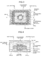
- FIG. 3 is a view, seen from above, of a housing room in a data center according to the second embodiment.
- the rack device 10 is arranged in such a way as to surround the air conditioning machine 11, the IT device 10a is housed in the rack device 10 in such a way as to take in air supplied under the floor via the grille 7 and discharge air to an area surrounded by the rack device 10.
- the air conditioning machine 11 is arranged in an area surrounded by the rack device 10 and at a side from which the IT device 10a discharges air in such a way as to surround an air conditioning machine pipe space 11a in which a pipe of the air conditioning machine is housed.
- a front surface as an air intake side of the IT device 10a faces the side of the grille 7 and a back surface as an air discharge side faces the side of the air conditioning machine 11.
- This arrangement allows the rack device 10 to insulate a cool air zone 20 where cooling air flowing into the housing room 2 from the space under the floor via the grille 7 concentrates and a discharged air zone 30 where discharged air, which is warmed air after being used for cooling the IT device 10a concentrates.
- an IT device can be safely cooled without a necessity of using a local cooling unit and a cooling efficiency in the data center can be enhanced.
- the discharged air zone according to the second embodiment compared to the first embodiment, is an area surrounded by the rack device 10 and the air conditioning machine 11 is arranged in the discharged air zone, discharged air is more quickly taken in by the air conditioning machine 11. Therefore, an increase in temperature in the entirety of the data center can be suppressed and a cooling efficiency can be enhanced, compared to the first embodiment.
- FIG. 4 is a cross-sectional view a section of which is obtained by a cutting along a line B-B' illustrated in FIG. 3 .
- cooling air supplied under the floor circulates upward from the floor via the grille 7 at a neighborhood of the wall 5. Therefore, the cooling air is supposed to pass under the floor of the discharged air zone and does not mix with discharged air.
- the air (discharged air) discharged from the IT device 10a is quickly taken in by the air conditioning machine 11, the discharged air does not mix with the cooling air passing through the grille 7. This configuration allows more strongly preventing an occurrence of a heat accumulated area compared to the first embodiment.
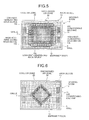
- FIG. 5 is a view, seen from above, of a housing room in a data center according to the third embodiment.
- the grille 7, the rack device 10, and the air conditioning machine 11 are arranged in the housing room 2 in the data center according to the third embodiment in the same way as the first embodiment.
- the rack device 10 surrounds the grille 7, the housed IT device 10a is arranged in such a way that its air intake side faces the side of the grille 7, and the air conditioning machine 11 is arranged in an area where discharged air of the IT device 10a concentrates.
- the rack device 10 allows insulation between a cool air zone 20 via the grille 7 and a discharged air zone 30 which is used by the IT device 10a for the cooling.
- the rack device 10 includes a high-heat-generating rack device 10b which has a plurality of high-performance IT devices 10a and of which heat generation amount is large, and a low-heat-generating rack device 10c which has a plurality of comparatively-low-performance IT devices 10a and of which heat generation amount is small, which is different from the first embodiment.
- the high-heat-generating rack device 10b discharges air of higher temperature than the low-heat-generating rack device 10c.
- the high-heat-generating rack device 10b is arranged at a place closer to the air conditioning machine 11 as illustrated in FIG. 5 .
- discharged air of higher temperature when discharged from the high-heat-generating rack device 10b can be taken in quickly by the air conditioning machine 11 without filling the housing room 2.
- a cooling efficiency in the data center can further be enhanced and an improvement in temperature in the housing room 2 can be prevented, compared to the case in which the arrangement of the high-heat-generating rack device 10b and the low-heat-generating rack device 10c is not taken into consideration.
- the embodiment is not limited thereto.
- the grille 7 can arranged to form a rhombus shape and the rack device 10 can also be arranged to form a rhombus shape in such a way as to surround the grille 7, as illustrated in FIG. 6 .
- the shape is not limited to the rhombus and may be any shapes such as a round shape and a polygonal shape as long as the cool air zone 20 and the discharged air zone 30 can be insulated.
- FIG. 6 is a view, seen from above, of a housing room when the rack device 10 is arranged to form a rhombus shape.
- the rack device 10 is not necessarily arranged in such a way as to surround the grille 7.
- the grille 7 and the rack device 10 can be arranged in such a way as to be parallel to either direction of the wall 5, as illustrated in FIG. 7 .
- This arrangement allows a division into the cool air zone 20 and the discharged air zone 30.
- FIG. 7 is a view, seen from above, of a housing room when the grille 7 and the rack device 10 are arranged in such a way as to be parallel to either direction of wall 5.
- the IT device 10a is housed in the rack device 10 so that its air intake side faces the side of the grille 7 and takes in cooling air from the grille 7.
- the air conditioning machine 11 is arranged at a side of the air discharge from the IT device 10a, i.e., in the discharged air zone 30, which is an area opposite to the grille 7 with respect to the rack device 10.
- This arrangement allows dividing the area into one cool air zone 20 and two discharged air zones 30. Therefore, an IT device can be safely cooled and a cooling efficiency in a data center can be enhanced similarly to the first to fourth embodiments.
- a plate 7a is arranged under the floor where the grille 7 is arranged in such a way as to be perpendicular to a surface of the grille 7 at a side opposite to the rack device 10, as illustrated in FIG. 8 .
- the cooling air under the floor goes upward by hitting the plate 7a under the grille 7.
- FIG. 8 illustrates the example of arranging a plate under the floor.
- a plate 7b is arranged on the floor where the grille 7 is arranged in such a way as to be perpendicular to a surface of the grille 7 at a side opposite to the rack device 10, as illustrated in FIG. 9 .
- This arrangement allows preventing the cooling air circulating from the space under the floor to the inside of the housing room 2 via the grille 7 from circulating to a direction opposite to the rack device 10, i.e., to a direction away from the rack device 10.
- the cooling air circulating in the housing room 2 is made to circulate to a side of the rack device 10, i.e., to a direction to the rack device 10.
- the IT device 10a housed in the rack device 10 can take in the cooling air efficiently.
- any materials such as a veneer plate, an acryl plate, and a concrete partition may be used.
- FIG. 9 illustrates the example of arranging a plate on the floor.
Landscapes
- Engineering & Computer Science (AREA)
- Computer Hardware Design (AREA)
- General Engineering & Computer Science (AREA)
- Physics & Mathematics (AREA)
- Thermal Sciences (AREA)
- Microelectronics & Electronic Packaging (AREA)
- Cooling Or The Like Of Electrical Apparatus (AREA)
Applications Claiming Priority (1)
| Application Number | Priority Date | Filing Date | Title |
|---|---|---|---|
| JP2009205327A JP5597957B2 (ja) | 2009-09-04 | 2009-09-04 | データセンター、冷却システムおよびit機器の冷却方法 |
Publications (2)
| Publication Number | Publication Date |
|---|---|
| EP2293659A2 true EP2293659A2 (fr) | 2011-03-09 |
| EP2293659A3 EP2293659A3 (fr) | 2011-07-13 |
Family
ID=43332638
Family Applications (1)
| Application Number | Title | Priority Date | Filing Date |
|---|---|---|---|
| EP10173477A Withdrawn EP2293659A3 (fr) | 2009-09-04 | 2010-08-19 | Centre de données, système de refroidissement et procédé de refroidissement de dispositif de technologie de l'information |
Country Status (4)
| Country | Link |
|---|---|
| US (1) | US20110059687A1 (fr) |
| EP (1) | EP2293659A3 (fr) |
| JP (1) | JP5597957B2 (fr) |
| CN (1) | CN102014596B (fr) |
Cited By (2)
| Publication number | Priority date | Publication date | Assignee | Title |
|---|---|---|---|---|
| DE202011050979U1 (de) | 2011-08-12 | 2011-11-08 | Innovit Ag | Rechenzentrum |
| DE102012001510A1 (de) | 2012-01-27 | 2013-08-01 | Bernd Schenk | Konstruktion für ein Rechenzentrum |
Families Citing this family (9)
| Publication number | Priority date | Publication date | Assignee | Title |
|---|---|---|---|---|
| JP2011257116A (ja) * | 2010-06-11 | 2011-12-22 | Fujitsu Ltd | 電算機室空調システム、その制御装置、プログラム |
| US8641492B2 (en) * | 2010-12-27 | 2014-02-04 | Gary Meyer | Directional flow raised floor air-grate |
| CN102955536A (zh) * | 2011-08-23 | 2013-03-06 | 鸿富锦精密工业(深圳)有限公司 | 货柜数据中心 |
| US9326430B2 (en) * | 2011-10-26 | 2016-04-26 | Hewlett Packard Enterprise Development Lp | Device for cooling an electronic component in a data center |
| WO2013145273A1 (fr) | 2012-03-30 | 2013-10-03 | 富士通株式会社 | Dispositif de traitement d'informations, procédé de commande et programme |
| JP2014127024A (ja) * | 2012-12-26 | 2014-07-07 | Hitachi Systems Ltd | ラックキャッピング装置 |
| CN104394678B (zh) * | 2014-12-12 | 2018-02-13 | 北京百度网讯科技有限公司 | 一种用于标准服务器的装置及其制造方法 |
| CN105159415A (zh) * | 2015-08-07 | 2015-12-16 | 诸暨市丝百内纺织品有限公司 | 一种新型柜式计算机装置 |
| CN105094254A (zh) * | 2015-08-07 | 2015-11-25 | 嘉兴市锐贝机械设备有限公司 | 一种用作网络服务器且可快速降温的柜式计算机装置 |
Family Cites Families (16)
| Publication number | Priority date | Publication date | Assignee | Title |
|---|---|---|---|---|
| US6538881B1 (en) * | 2000-06-12 | 2003-03-25 | Alcatel Canada Inc. | Cooling of electronic equipment |
| US7313503B2 (en) * | 2002-02-19 | 2007-12-25 | Hewlett-Packard Development Company, L.P. | Designing layout for internet datacenter cooling |
| GB0207382D0 (en) * | 2002-03-28 | 2002-05-08 | Holland Heating Uk Ltd | Computer cabinet |
| US7841199B2 (en) * | 2005-05-17 | 2010-11-30 | American Power Conversion Corporation | Cold aisle isolation |
| LU91207B1 (fr) * | 2005-11-11 | 2007-05-14 | Uniflair Ind S P A | Système de refroidissement pour une pièce contenant de l'équipement électronique de traitement de données |
| JP4873997B2 (ja) * | 2006-05-26 | 2012-02-08 | ヤフー株式会社 | 機器収容ラックおよび機器収容室用空調システム |
| EP2036412B1 (fr) * | 2006-06-01 | 2012-11-14 | Exaflop LLC | Capture commandée d'air chaud |
| NL1032450C2 (nl) * | 2006-09-06 | 2008-03-07 | Uptime Technology B V | Inrichting en werkwijze voor het met behulp van recirculatielucht koelen van een ruimte in een datacentrum. |
| US7716939B1 (en) * | 2006-09-26 | 2010-05-18 | Amazon Technologies, Inc. | Method and apparatus for cooling electronic components |
| JP4983550B2 (ja) * | 2007-11-01 | 2012-07-25 | 富士通株式会社 | 冷却補助ユニット及び冷却システム |
| US7907402B2 (en) * | 2007-11-09 | 2011-03-15 | Panduit Corp. | Cooling system |
| EP2059105B1 (fr) * | 2007-11-09 | 2012-01-04 | Knürr GmbH | Système et procédé pour le contrôle climatique |
| US8351200B2 (en) * | 2007-11-19 | 2013-01-08 | International Business Machines Corporation | Convergence of air water cooling of an electronics rack and a computer room in a single unit |
| JP2009140421A (ja) * | 2007-12-10 | 2009-06-25 | Toyo Netsu Kogyo Kk | サーバラック及びこれを備えたデータセンター |
| JP5176702B2 (ja) * | 2008-06-05 | 2013-04-03 | 富士通株式会社 | 格納装置および情報処理装置並びに冷却方法 |
| JP2009079890A (ja) * | 2008-10-02 | 2009-04-16 | Softbank Idc Corp | 空調システム |
-
2009
- 2009-09-04 JP JP2009205327A patent/JP5597957B2/ja not_active Expired - Fee Related
-
2010
- 2010-08-19 EP EP10173477A patent/EP2293659A3/fr not_active Withdrawn
- 2010-09-01 US US12/873,909 patent/US20110059687A1/en not_active Abandoned
- 2010-09-02 CN CN2010102720598A patent/CN102014596B/zh not_active Expired - Fee Related
Non-Patent Citations (2)
| Title |
|---|
| JOHN NIEMANN: "Hot-aisle vs. cold-aisle containment", WHITE PAPER #135 OF AMERICAN POWER CONVERSION CORP., 2008 |
| WHITE PAPER LJTC040202TB OF HEWLETT-PACKARD DEVELOPMENT COMPANY, February 2004 (2004-02-01) |
Cited By (2)
| Publication number | Priority date | Publication date | Assignee | Title |
|---|---|---|---|---|
| DE202011050979U1 (de) | 2011-08-12 | 2011-11-08 | Innovit Ag | Rechenzentrum |
| DE102012001510A1 (de) | 2012-01-27 | 2013-08-01 | Bernd Schenk | Konstruktion für ein Rechenzentrum |
Also Published As
| Publication number | Publication date |
|---|---|
| JP2011059741A (ja) | 2011-03-24 |
| EP2293659A3 (fr) | 2011-07-13 |
| US20110059687A1 (en) | 2011-03-10 |
| CN102014596B (zh) | 2013-06-12 |
| CN102014596A (zh) | 2011-04-13 |
| JP5597957B2 (ja) | 2014-10-01 |
Similar Documents
| Publication | Publication Date | Title |
|---|---|---|
| EP2293659A2 (fr) | Centre de données, système de refroidissement et procédé de refroidissement de dispositif de technologie de l'information | |
| JP5296457B2 (ja) | 空調システム | |
| RU2562442C2 (ru) | Герметизация охлаждающих рядов для систем охлаждения серверных ферм | |
| US20200146177A1 (en) | Energy saving system and method for cooling computer data center and telecom equipment | |
| JP5605982B2 (ja) | 換気装置および空調換気システム | |
| RU2510523C2 (ru) | Интегрированный на основе здания блок перемещения воздуха для системы охлаждения серверной фермы | |
| RU2318299C2 (ru) | Система охлаждения для приборных и сетевых шкафов и способ охлаждения приборных и сетевых шкафов | |
| US20100248609A1 (en) | Assembly For Providing A Downflow Return Air Supply | |
| US20120100795A1 (en) | Air-conditioning system | |
| EP2369256A1 (fr) | Système de climatisation pour des salles de serveurs | |
| JP5600388B2 (ja) | サーバ室の空調システム | |
| US20110209852A1 (en) | Method and system for cooling apparatus racks | |
| CN110290676B (zh) | 集装箱计算中心 | |
| JP6309783B2 (ja) | 空調システム | |
| CN109634391B (zh) | 散热设备 | |
| JP7298216B2 (ja) | サーバ冷却装置、サーバシステム及びサーバの冷却方法 | |
| EP3637004A1 (fr) | Unité extérieure d'appareil de réfrigération | |
| JP6137528B2 (ja) | データセンターの構造、およびデータセンターの空調方法 | |
| Hannaford | Ten cooling solutions to support high-density server deployment | |
| JP5389699B2 (ja) | 発熱機器用のラック空調装置 | |
| EP3989690B1 (fr) | Dispositif de communication | |
| JP5854088B2 (ja) | サーバ室の空調システム | |
| JP6271128B2 (ja) | 空調システム | |
| JP2011134803A (ja) | 電子機器収納ラック群の冷却装置及び方法 | |
| US20070243814A1 (en) | Enclosure unit and electronic apparatus |
Legal Events
| Date | Code | Title | Description |
|---|---|---|---|
| PUAI | Public reference made under article 153(3) epc to a published international application that has entered the european phase |
Free format text: ORIGINAL CODE: 0009012 |
|
| AK | Designated contracting states |
Kind code of ref document: A2 Designated state(s): AL AT BE BG CH CY CZ DE DK EE ES FI FR GB GR HR HU IE IS IT LI LT LU LV MC MK MT NL NO PL PT RO SE SI SK SM TR |
|
| AX | Request for extension of the european patent |
Extension state: BA ME RS |
|
| PUAL | Search report despatched |
Free format text: ORIGINAL CODE: 0009013 |
|
| AK | Designated contracting states |
Kind code of ref document: A3 Designated state(s): AL AT BE BG CH CY CZ DE DK EE ES FI FR GB GR HR HU IE IS IT LI LT LU LV MC MK MT NL NO PL PT RO SE SI SK SM TR |
|
| AX | Request for extension of the european patent |
Extension state: BA ME RS |
|
| 17P | Request for examination filed |
Effective date: 20120109 |
|
| STAA | Information on the status of an ep patent application or granted ep patent |
Free format text: STATUS: THE APPLICATION HAS BEEN WITHDRAWN |
|
| 18W | Application withdrawn |
Effective date: 20140618 |