EP2293877B1 - Appareil de réduction conique - Google Patents
Appareil de réduction conique Download PDFInfo
- Publication number
- EP2293877B1 EP2293877B1 EP09769335.2A EP09769335A EP2293877B1 EP 2293877 B1 EP2293877 B1 EP 2293877B1 EP 09769335 A EP09769335 A EP 09769335A EP 2293877 B1 EP2293877 B1 EP 2293877B1
- Authority
- EP
- European Patent Office
- Prior art keywords
- crusher
- impeller
- milling
- spindle
- crushing
- Prior art date
- Legal status (The legal status is an assumption and is not a legal conclusion. Google has not performed a legal analysis and makes no representation as to the accuracy of the status listed.)
- Active
Links
Images



Classifications
-
- B—PERFORMING OPERATIONS; TRANSPORTING
- B02—CRUSHING, PULVERISING, OR DISINTEGRATING; PREPARATORY TREATMENT OF GRAIN FOR MILLING
- B02C—CRUSHING, PULVERISING, OR DISINTEGRATING IN GENERAL; MILLING GRAIN
- B02C2/00—Crushing or disintegrating by gyratory or cone crushers
- B02C2/10—Crushing or disintegrating by gyratory or cone crushers concentrically moved; Bell crushers
-
- B—PERFORMING OPERATIONS; TRANSPORTING
- B02—CRUSHING, PULVERISING, OR DISINTEGRATING; PREPARATORY TREATMENT OF GRAIN FOR MILLING
- B02C—CRUSHING, PULVERISING, OR DISINTEGRATING IN GENERAL; MILLING GRAIN
- B02C13/00—Disintegrating by mills having rotary beater elements ; Hammer mills
- B02C13/14—Disintegrating by mills having rotary beater elements ; Hammer mills with vertical rotor shaft, e.g. combined with sifting devices
- B02C13/18—Disintegrating by mills having rotary beater elements ; Hammer mills with vertical rotor shaft, e.g. combined with sifting devices with beaters rigidly connected to the rotor
-
- B—PERFORMING OPERATIONS; TRANSPORTING
- B02—CRUSHING, PULVERISING, OR DISINTEGRATING; PREPARATORY TREATMENT OF GRAIN FOR MILLING
- B02C—CRUSHING, PULVERISING, OR DISINTEGRATING IN GENERAL; MILLING GRAIN
- B02C18/00—Disintegrating by knives or other cutting or tearing members which chop material into fragments
- B02C18/06—Disintegrating by knives or other cutting or tearing members which chop material into fragments with rotating knives
- B02C18/062—Disintegrating by knives or other cutting or tearing members which chop material into fragments with rotating knives with rotor elements extending axially in close radial proximity of a concentrically arranged slotted or perforated ring
-
- B—PERFORMING OPERATIONS; TRANSPORTING
- B02—CRUSHING, PULVERISING, OR DISINTEGRATING; PREPARATORY TREATMENT OF GRAIN FOR MILLING
- B02C—CRUSHING, PULVERISING, OR DISINTEGRATING IN GENERAL; MILLING GRAIN
- B02C18/00—Disintegrating by knives or other cutting or tearing members which chop material into fragments
- B02C18/06—Disintegrating by knives or other cutting or tearing members which chop material into fragments with rotating knives
- B02C18/08—Disintegrating by knives or other cutting or tearing members which chop material into fragments with rotating knives within vertical containers
-
- B—PERFORMING OPERATIONS; TRANSPORTING
- B02—CRUSHING, PULVERISING, OR DISINTEGRATING; PREPARATORY TREATMENT OF GRAIN FOR MILLING
- B02C—CRUSHING, PULVERISING, OR DISINTEGRATING IN GENERAL; MILLING GRAIN
- B02C18/00—Disintegrating by knives or other cutting or tearing members which chop material into fragments
- B02C18/06—Disintegrating by knives or other cutting or tearing members which chop material into fragments with rotating knives
- B02C18/08—Disintegrating by knives or other cutting or tearing members which chop material into fragments with rotating knives within vertical containers
- B02C18/12—Disintegrating by knives or other cutting or tearing members which chop material into fragments with rotating knives within vertical containers with drive arranged below container
Definitions
- the present disclosure relates to an apparatus for reducing the size of large material lumps into fine particles.
- coarse blocks of about 50 cm in size and above are processed on a minimum of two equipments in order to reach approximately particles with a diameter of the order of 500 ⁇ m.
- a crusher is commonly used as a first step in the milling process.
- DE1141517 discloses an apparatus for cutting up, mixing and homogenize material mixtures comprising a crushing device disposed above a milling device comprising a sieve having a frusto-conical shape.
- the crusher device and the milling device are connected via a connecting part destined to provide holes used to homogenize the crushed products coming from the crusher device.
- DE3617175 describes a device for comminuting and screening a dry material and comprising a comminuting element disposed above and connected to a milling device.
- Patent US5330113 discloses a milling device for use in process industries to continuously and precisely reduce the size of particles, while controlling fines, comprises an impeller mounted on a rotatable shaft, a drive operably connected to the shaft for effecting rotation of the shaft.
- the shaft and impeller are vertically mounted within a vertically extending channel having an input and an output.
- a screen has a tapered apertured wall formed in a frusto-conical shape. The screen is rigidly mounted within the channel so that any particles passing from the input to the output pass through the screen.
- a milling device allowing for an easy and in-place cleaning, that could be smaller and more modular for multi-product manufacturing is still wanted.
- a crusher device for reducing the size of material can comprise a hollow part of frusto-conical shape narrowing downwardly, a crusher spindle rotatably mounted coaxial with the hollow part, at least one crusher impeller rotatably mounted on the crusher spindle, and a crusher driving device for rotatably driving said at least one crusher impeller relative to said first hollow part; wherein said at least one crusher impeller can comprise a first crusher impeller containing a first crushing blade and a second crushing blade, each said first and second crushing blades extending radially from the crusher spindle and being fixedly connected to each other at their distal extremities by a blade member.
- said first crusher impeller can comprise a third crushing blade extending radially from the crusher spindle, below the first and second crushing blades.
- said first crusher impeller can further comprise an unbalancing blade to impede the material lump rotating with the first impeller.
- said first crushing blade and second crushing blade can be offset angularly.
- said first and second crushing blades can comprise a sharpened cutting edge.
- the cutting edge can further comprise serrations along at least a portion of the cutting edge.
- said first crusher impeller can further comprise a fourth crushing blade extending radially and downward from the crusher spindle, below the third crushing blade.
- said crusher device can further comprises a second crusher impeller.
- the second crusher impeller can comprise an outer ring mounted rotatably and coaxially on the crusher spindle, said outer ring containing one or several outer crushing teeth along its periphery.
- the second crusher impeller can further comprise an inner ring fixed to the outer ring and rotating with it, said inner ring containing one or several inner crushing teeth along its periphery.
- said outer and inner rings can contain three outer and three inner crushing teeth, respectively.
- the crusher device can comprises at least one static element to impede possible rotation of the material to be crushed with said at least one crusher impeller.
- Said at least one static element can comprise one or several stator elements fixed on the hollow part, above the first crusher impeller, or one or several static blades fixed on the crusher driving element, or one or several lower stator elements arranged radially around the lower end of the hollow part, or the crusher driving element.
- said crusher device can further comprises a torque detection device able to detect a predetermined high torque value of the crusher spindle, said torque detection device controlling the crusher driving device to adjust the rotation speed and/or rotation direction of the crusher spindle when the predetermined high torque value is detected.
- the present disclosure also pertains to an apparatus for reducing the size of material, comprising a milling device containing a sieve and a milling impeller, said milling impeller being rotated relative to the interior wall surface of the sieve, said sieve having a frusto-conical shape narrowing downwardly, and said milling impeller is vertically mounted within the sieve; and the crusher device; wherein the crusher device being connectable to the milling device such that the frusto-conical shape of the sieve of the milling device extends the frusto-conical shape of the hollow part of the crusher device.
- the milling spindle can be mounted on a rotatable milling spindle, the milling spindle being rotatably driven by the crusher spindle.
- the milling spindle can be rotatably driven by the fourth crushing blade.
- said milling impeller can be rotated relative to the interior wall surface of the sieve such that during a reducing operation, said material is first crushed by the crusher device by rotating said at least one crusher impeller, and milled by the milling device by rotating the milling impeller.
- the apparatus disclosed herein can be manufactured at low cost and is of compact size. Using the disclosed apparatus, material having a size up to 36000 cm 3 can be reduced effectively to particles having a size below 250 microns in diameter.
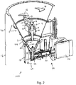
- FIG. 1 A side view of an apparatus 100 for reducing the size of material according to an embodiment of the invention is shown in Fig. 1 , while a cross-section view of the apparatus 100 is shown in Fig. 2 according to a cut made in the vertical plan of the Fig. 1 .
- the apparatus comprises a crusher device 40 comprising a hollow part 1 having the shape of a truncated cone revolving around a crusher axis 10, and narrowing downwardly toward a lower end 44.
- the hollow part 1 consists of a first hollow part 2a and a second hollow part 2b, the second hollow part 2b being fixedly connected to the first hollow part 2a, extending upward the first hollow part 2a.
- the shape of the hollow part 1, or second hollow part 2b is advantageous for introducing the material to be reduced into the crusher device 40, and has other functionalities that will be described below.
- the crusher device 40 further comprises a crusher spindle 5 rotatably mounted coaxial with the hollow part 1, a crusher rotor 4 and a first crusher impeller 9 rotatably mounted on the crusher spindle 5.
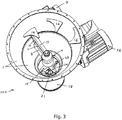
- the crusher spindle 5 is driven by a crusher driving device comprising a crusher motor 7 (partially shown in Fig. 3 ) drivingly connected to the crusher spindle 5 via a gearbox 6, enclosing the spindle 5, and a crusher driving element 8.
- a crusher driving device comprising a crusher motor 7 (partially shown in Fig. 3 ) drivingly connected to the crusher spindle 5 via a gearbox 6, enclosing the spindle 5, and a crusher driving element 8.
- the crusher driving element 8 extends radially between the hollow part 1 and the gearbox 6.
- the crusher driving device can extend coaxially with the crusher spindle 5. Such arrangement does not necessitate the use of the gearbox 6.
- the first crusher impeller 9 comprises a first and a second crushing blade 11, 13, both blades 11, 13 extending radially from the crusher spindle 5 and being fixedly connected to each other at their distal extremities, toward the hollow part 1, by a blade member 12.
- the blade member 12 is inclined substantially parallel to the wall of the hollow part 1, producing a constant gap between the blade member 12 and the internal wall of the hollow parts 1. Other inclination angles of the blade member 12 are however possible.
- the first and second crushing blades 11, 13 are offset with an angle ⁇ , where ⁇ can have any value comprised between 0 and 90°. This configuration minimizes the risk that a lump of material remains blocked between the two crushing blades 11, 13 and rotates with the first crusher impeller 9, preventing effective crushing of the material.
- the first and second crushing blades 11, 13 have a sharpened cutting edge 27, diminishing the contact surface between the crushing blades 11, 13 and the material to be crushed, and thus increasing the pressure exerted on the material by the crushing blades 11, 13. This results in an increased crunching efficiency, mainly due to the increased penetration of the crushing blades 11, 13 and enhanced crack initiation in the material.
- at least a portion of the cutting edge 27 of the first and/or the second crushing blades comprises serrations 28.
- the first crusher impeller 9 can further comprise an unbalancing blade 45 fixed on top of the second crushing blade 13. The unbalancing blade 45 allows avoiding the material lump to sit and rotate with the first crusher impeller 9 without being crushed, when introduced into the crusher device 40.
- the first crusher impeller 9 comprises a third crushing blade 14 extending radially from the first rotor 4, below the first and second crushing blades 11, 13.
- the third crushing blade 14 can improve the crushing efficiency by crushing further fragments of material produced by the first and second crushing blades 11, 13.
- the third crushing blade 14 has a distal end oriented upward possibly inclined substantially parallel to the hollow part 1.
- the first crusher impeller 9 can also comprise a fourth crushing blade 15 extending radially, below the third crushing blade 14.
- the distal end of fourth crushing blade 15 is bended downward.
- the fourth crushing blade 15 can be used to further enhance the crushing of the fragments of material produced by the first and second blades 11, 13, and possible by the third crushing blade 14.
- the first crusher impeller 9 can be formed from a single piece. However, the first and second crushing blades 11, the blade member 12, and the crusher rotor 4 can also be made from separate parts assembled by welding or any other suitable means.
- the crusher device further comprises a second impeller 30 formed from an outer ring 34 containing one or several outer crushing teeth 340.
- the outer ring 34 is fixedly attached to a second impeller rotor 31 by six arms 33 extending radially from the rotor 31 to the outer ring 34. Any other attachment means are however possible including a disc containing openings sufficiently large to let crushed material fragments pass through them.
- the second impeller 30 is mounted rotatably and coaxially on the crusher spindle 5 by driving an aperture 32 provided on the rotor 31 onto the crusher spindle 5.
- the number of outer crushing teeth 340 is chosen such as, during the crushing operation, the material to be crunched is seized by only one tooth at a given time.
- the outer ring 34 comprises three outer crushing teeth 340 oriented upward and equally distributed, along the outer ring periphery.
- the second impeller 30 further comprises an inner ring 35 containing one or several inner crushing teeth 350, the inner ring 35 being fixed to the outer ring 34 and rotating with it.
- the inner ring 35 contains three inner crushing teeth 350 oriented upward and equally distributed, along the inner ring periphery.
- the outer and inner rings 34, 35 of the second impeller 30 can be made from separate parts assembled by welding or any other suitable means. However, the second impeller 30 is preferably made from a single piece.
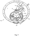
- the second impeller 30 is preferably rotatably mounted on the lower extremity of the crusher spindle 5, in the vicinity of the lower end 44 of the hollow part 1, as shown in the example of Fig. 7 representing a perspective view of the crusher device 40.
- the crusher device 40 can comprise a static device able to impede possible rotation of the material with first and/or second impeller 9, 30. Indeed, during the crushing operation, large material lumps can be carried by the first and/or second impeller 9, 30, and start rotating with them. In this case, the material cannot be crushed effectively.
- the static device can be used to impede the rotation of the material and force the first and/or second impellers 9, 30 to break to material, thus enhancing the crushing efficiency.
- the static device comprises one or several stator elements 16 fixed on the internal wall of the hollow part 1.
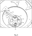
- the stator elements 16 can be seen extending radially toward the crusher axis 10. More particularly, in Figs. 2 to 4 three stator elements 16 are fixed on the upper end of the hollow part 1, above the first crusher impeller 9.
- the static device comprises one or several static blades 36 fixed on the crusher driving element 8.
- the static blades 36 are fixed on the lower side of the crusher driving element 8 in a configuration allowing the outer and inner crushing teeth 340, 350 of the second crusher impeller 30 to pass sequentially between the static blades 36 when the second impeller 30 rotates.
- the static blades 36 advantageously force the outer and/or inner crushing teeth 340, 350 to seize the material and break it, thus, increasing the crushing efficiency.
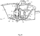
- one or several additional static blades 36b can be fixed on the lateral side if the crusher driving element 8 as shown in the example of Fig. 8 .
- the static device comprises one or several lower stator elements 37 fixed radially around the periphery of the internal wall of the lower part of the hollow part 1, for example, around the lower end 44.
- the lower stator elements 37 are arranged equally spaced.
- the lower stator elements 37 can be advantageous used to improve fine crushing efficiency, in particular with slippery materials such as ice.
- the apparatus 100 further comprises a milling device 17, formed from a sieve 19 and a tubular frame 18 in which the sieve 19 is coaxially mounted.
- the sieve 19 has a frusto-conical shape narrowing downwardly, with an open upper wide end 42 and a lower narrow end 43 being at least partially closed. In most uses, it is desirable to have the lower narrow end 43 completely closed.
- the milling device 17 further comprises a milling impeller 21 mounted on a rotatable milling spindle 22, both milling impeller 21 and milling spindle 22 being vertically mounted within the sieve 19.
- the milling impeller 21 comprises two symmetrical milling blades 23.
- the milling impeller 21 can comprises several blades 23 equally distributed around the milling rotor 21 or distributed according to any other arrangement.
- a constant gap is formed between the peripheral edge of the milling blade 23 and the interior wall of the sieve 19.
- the milling impeller 21 rotates relative to the interior wall surface of the sieve 19 for milling the material inputted from the upper wide end 42 by passing said material through the sieve 19.
- the milled material is then leaves the milling device 17 by an exit 25.
- Such a milling device is described in more details in U.S. Patent No 5,863,004 by the present applicant.
- the milling device 17 is susceptible to various modifications and alternative forms.
- the sieve 19 can be disk-shaped or have a tubular shape, with the milling blade 23 rotating relative to the disk-shaped or tubular-shaped sieve 19, respectively.
- the milling device 17 is connected below the crusher device 40, the upper wide end 42 of the sieve 19 being vertically connected to the lower end 44 of the hollow part 1.
- the hollow part 1 of the crusher device 40 can be connected to the sieve 19, by connecting a lower flange 3, comprised at the lower end 44 of the hollow part 1, to an upper flange 20, comprised on the upper side of the tubular frame 18.
- the milling device 17 is connected coaxially with the crusher device 40. In this configuration, the conical sieve 19 of the milling device 17 is prolonged by the conical-shaped hollow part 1 of the crusher device 40.
- the milling rotor 21 can be driven by connecting the fourth crushing blade 15 to the milling impeller 21, for example, by one of the milling blades 23, as shown in Fig. 2 .
- the milling spindle 22 can be connected to the crusher spindle 5.
- the milling impeller 21 is driven by a milling driving device 24 comprising a milling motor 26 and a milling driving element 41, the milling driving device 24 driving the milling spindle 22.
- the different parts of the crusher device 40 and of the milling device 17 are made in stainless steel to make the apparatus 100 compatible for use in a sanitary environment such as in pharmaceutical applications.
- the material is inputted into the hollow part 1 and is crushed by the action of the first and/or second crusher impeller 9, 30.
- This crushing operation produces crushed material fragments that enter, by gravity, the milling device 17 disposed below the crusher device 40.
- the crushed material is then milled in the milling device 17 by being pressed through the sieve 19 when the milling impeller 21 is rotated.
- the milled material having the form of fine particles, leaves the milling device 17 through the output 25.
- the crushing efficiency can be increased by using the second impeller 30 and/or by using the static device according to any of the embodiments disclosed herein.
- the combined action of the second impeller 30 with the static blades 36 produces a flux of crushed material entering the milling device 17 that is more regular than in the absence of the second impeller 30.
- the crushed material entering the milling device 17 is less likely to escape the milling device 17 toward the crusher device 40 under the action of the centrifugal forces.
- the crusher device 40 is of simple construction and contains no sieve, the device 40 is very easy to clean, even allowing for easy cleaning-in-place (CIP) and washing-in-place (WIP) processes.
- CIP cleaning-in-place
- WIP washing-in-place
- the crusher device 40 Due to its conical shape and the geometry if the first and/or second crusher impeller 9, 30, the crusher device 40 is able to prevent clogging of powder materials and/or can be used for disagglomeration of materials that have become hardened and lumpy over time and sizes them into free-flowing powder.
- the crusher device 40 further comprises a torque detection device able to detect a predetermined high torque value of the crusher spindle 5.
- Such high torque value of the crusher spindle 5 can correspond, for example, to the first and/or second impeller 9, 30 being jammed by hard material fragments.
- the torque detection device can control the crusher driving device, or the crusher motor 7, and adjust the rotation speed and/or rotation direction of the crusher spindle 5 when the predetermined high torque value is detected.
- the first and/or second impellers 9, 30 can be halted, and/or the rotation of the first and/or second impellers 9, 30 can be inversed during a predetermined time period, in order to release the impellers 9, 30. After releasing, the impellers 9, 30 can be rotated to their normal crushing rotation speed and direction to carry on with the crushing operation.
- the apparatus 100 further comprises a weight metering device able to measure, possibly continuously, a weight of the milled material.
- the weight metering device can be a gravimetric measurement instrument such as a balance, disposed below the milling device 17 and receiving the material milled by the milling device 17.
- the weight metering device can possibly control the milling driving device 24, or the milling motor 26, in order to adjust the rotation speed of the milling spindle 22, or milling impeller 21, as a function of a predetermined weight set point.
- the weight metering device can set a lower rotation speed of the milling impeller 21 when the weight set point corresponds to a lower milling material weight, than when the weight set point corresponds to a higher milling material weight.
Landscapes
- Engineering & Computer Science (AREA)
- Food Science & Technology (AREA)
- Mechanical Engineering (AREA)
- Crushing And Pulverization Processes (AREA)
- Disintegrating Or Milling (AREA)
Claims (14)
- Dispositif de broyage/concassage (40) pour effectuer une opération de broyage, comprenant une partie creuse (1) de forme tronconique se rétrécissant vers le bas, une broche de broyeur (5) montée en rotation coaxiale avec la partie creuse (1), au moins une roue de broyeur (9, 30) montée en rotation sur la broche de broyeur (5), et un dispositif d'entraînement de broyeur pour entraîner en rotation ladite au moins une roue de broyeur (9, 30) par rapport à ladite première partie creuse (2);
caractérisé en ce que
ladite première roue de broyeur comprend une première roue de broyeur (9) contenant une première lame de broyage (11) et une deuxième lame de broyage (13), chacune de ladite première et deuxième lame de broyage (11, 13) s'étendant radialement à partir de la broche de broyeur (5) et étant reliée solidairement l'une à l'autre à leurs extrémités distales par un organe de lame (12). - Dispositif de broyage (40) selon la revendication 1, dans lequel ladite première roue de broyeur (9) comprend une troisième lame de broyage (14) s'étendant radialement à partir de la broche de broyeur (5), en-dessous de la première et deuxième lame de broyage (11, 13).
- Dispositif de broyage (40) selon l'une des revendications 1 ou 2, dans lequel ladite première roue de broyeur (9) comprend en outre une lame de déséquilibrage (45) pour empêcher la masse de matériau de tourner avec la première roue de broyeur (9).
- Dispositif de broyage (40) selon la revendication 2, dans lequel ladite première roue de broyeur (9) comprend en outre une quatrième lame de broyage (15) s'étendant radialement et vers le bas à partir de la broche de broyeur (5), en-dessous de la troisième lame de broyage (14).
- Dispositif de broyage (40) selon l'une quelconque des revendications 1 à 4, dans lequel ledit dispositif de broyage (40) comprend en outre une deuxième roue de broyeur (30).
- Dispositif de broyage (40) selon la revendication 5, dans lequel ladite deuxième roue de broyeur (30) comprend un anneau extérieur (34) monté en rotation et coaxialement sur la broche de broyeur (5), ledit anneau extérieur (34) contenant une ou plusieurs dents de broyage externes (340) le long de sa périphérie.
- Dispositif de broyage (40) selon la revendication 5, dans lequel ladite deuxième roue de broyeur (30) comprend en outre un anneau intérieur (35) fixé à l'anneau extérieur (34) et tournant avec lui, ledit anneau intérieur (35) contenant une ou plusieurs dents de broyage externes (350) le long de sa périphérie.
- Dispositif de broyage (40) selon l'une quelconque des revendications 1 à 7, dans lequel le dispositif de broyage (40) comprend au moins un élément statique (16, 36, 37) pour empêcher une rotation possible du matériau à broyer avec ladite au moins une roue de broyeur (9, 30).
- Dispositif de broyage (40) selon la revendication 8, dans lequel le au moins un élément statique comprend un ou plusieurs éléments de stator (16) fixés sur la partie creuse (1), au-dessus de la première roue de broyeur (9), ou un ou plusieurs éléments de stator inférieurs (37) disposés radialement autour de l'extrémité inférieure de la partie creuse (1), ou une ou plusieurs lames statiques (36) fixés sur un élément d'entraînement de broyeur (8) qui s'étend radialement entre la partie creuse (1) et une boîte de vitesses (6), un moteur de broyeur (7) étant relié en entraînement à une broche de broyeur (5) au travers de la boîte de vitesses (6) et l'élément d'entraînement de broyeur (8).
- Dispositif de broyage (40) selon l'une quelconque des revendications 1 à 9, dans lequel ledit dispositif de broyage (40) comprend en outre un dispositif de détection de couple capable de détecter une valeur de couple élevée prédéterminée de la broche de broyeur (5), ledit dispositif de détection de couple commandant le dispositif d'entraînement de broyeur pour ajuster le la vitesse de rotation et/ou la direction de rotation de la broche de broyeur (5) lorsque la valeur de couple élevée prédéterminée est détectée.
- Appareil (100) pour réduire la taille de matériau, comprenant :un dispositif de fraisage (17) contenant un tamis (19) et une roue de fraisage (21), ladite roue de fraisage (21) étant mise en rotation par rapport à la surface de paroi intérieure du tamis (19), ledit tamis (19) ayant une forme tronconique se rétrécissant vers le bas, et ladite roue de fraisage (21) étant montée verticalement au sein du tamis (19) ; etle dispositif de broyage (40) selon l'une quelconque des revendications 1 à 10 ;caractérisé en ce quele dispositif de broyage (40) peut être relié au dispositif de fraisage (17) de telle sorte que la forme tronconique du tamis (19) du dispositif de tamis (17) étend la forme tronconique de la partie creuse (1) du dispositif de broyage (40).
- Appareil (100) selon la revendication 11, dans lequel le dispositif de broyage (40) comprend une quatrième lame de broyage (15), et dans lequel la broche de fraisage (22) est entraînée en rotation par la quatrième lame de broyage (15).
- Appareil (100) selon les revendications 11 ou 12, dans lequel ledit dispositif de broyage (40) comprend un moteur de broyeur (7), une boîte de vitesses (6) et un élément d'entraînement de broyeur (8), ledit moteur de broyeur (7) étant reliée en entraînement avec la broche de broyeur (5) au travers de la boîte de vitesses (6) et l'élément d'entraînement de broyeur (8).
- Appareil (100) selon l'une quelconque des revendications 11 à 13, dans lequel ladite roue de fraisage (21) est mise en rotation par rapport à la surface de paroi intérieure du tamis (19) et dans lequel, pendant une opération de réduction, ledit matériel est d'abord broyé par le dispositif de broyage (40) par rotation de ladite au moins une roue de broyeur (9, 30) et fraisé par le dispositif de fraisage (17) par rotation de la roue de fraisage (21).
Priority Applications (1)
| Application Number | Priority Date | Filing Date | Title |
|---|---|---|---|
| EP09769335.2A EP2293877B1 (fr) | 2008-06-26 | 2009-06-25 | Appareil de réduction conique |
Applications Claiming Priority (3)
| Application Number | Priority Date | Filing Date | Title |
|---|---|---|---|
| EP08159142 | 2008-06-26 | ||
| EP09769335.2A EP2293877B1 (fr) | 2008-06-26 | 2009-06-25 | Appareil de réduction conique |
| PCT/EP2009/058003 WO2009156487A2 (fr) | 2008-06-26 | 2009-06-25 | Appareil de réduction conique |
Publications (2)
| Publication Number | Publication Date |
|---|---|
| EP2293877A2 EP2293877A2 (fr) | 2011-03-16 |
| EP2293877B1 true EP2293877B1 (fr) | 2017-11-29 |
Family
ID=41061139
Family Applications (1)
| Application Number | Title | Priority Date | Filing Date |
|---|---|---|---|
| EP09769335.2A Active EP2293877B1 (fr) | 2008-06-26 | 2009-06-25 | Appareil de réduction conique |
Country Status (4)
| Country | Link |
|---|---|
| US (1) | US8662430B2 (fr) |
| EP (1) | EP2293877B1 (fr) |
| CN (1) | CN102143800B (fr) |
| WO (1) | WO2009156487A2 (fr) |
Families Citing this family (15)
| Publication number | Priority date | Publication date | Assignee | Title |
|---|---|---|---|---|
| PT2660161T (pt) * | 2012-05-04 | 2017-11-09 | Tpresso Ag | Acondicionamento de folhas secas em cápsulas herméticas |
| JP5799349B2 (ja) * | 2012-07-24 | 2015-10-21 | 国立研究開発法人農業・食品産業技術総合研究機構 | 裏漉し機の運転方法及び自動裏漉し装置 |
| CN105167664B (zh) * | 2015-09-30 | 2017-09-12 | 重庆岩泉食品有限公司 | 称重式干果粉碎器 |
| CN105728153B (zh) * | 2016-03-08 | 2017-11-28 | 杨露萍 | 一种制药车间用中药多重粉碎装置 |
| CN105921219B (zh) * | 2016-06-07 | 2018-03-20 | 佳科国际股份有限公司 | 立式破碎粉碎机 |
| CH712632A2 (fr) | 2016-06-28 | 2017-12-29 | Frewitt Fabrique De Machines Sa | Dispositif de broyage. |
| CN107097277A (zh) * | 2017-04-25 | 2017-08-29 | 朱玉波 | 一种中药循环提取预处理装置 |
| CN107020046B (zh) * | 2017-05-15 | 2019-09-06 | 南京工程学院 | 一种适用于离心筛选的固体混料器 |
| CN108745476B (zh) * | 2018-06-19 | 2019-10-18 | 宁远县豪杰农业发展有限公司 | 一种油茶籽加工设备 |
| CN108970766B (zh) * | 2018-09-07 | 2021-01-05 | 张家港市新贝机械有限公司 | 一种单轴撕碎机 |
| CN109847876B (zh) * | 2018-12-15 | 2021-01-29 | 李润凡 | 一种破碎效果好的厨房垃圾处理装置 |
| MX2021011721A (es) * | 2019-03-27 | 2021-10-22 | Sgs North America Inc | Dispositivo para probar molienda de una muestra de mena. |
| CN110721897B (zh) * | 2019-09-19 | 2022-03-22 | 桂林理工大学 | 一种建筑垃圾烧陶粒用原料筛选装置 |
| CN114260073A (zh) * | 2021-11-16 | 2022-04-01 | 山东康美药业有限公司 | 一种药品生产用切块研磨装置 |
| CN119158654B (zh) * | 2024-11-19 | 2025-01-28 | 内蒙古沙漠之花生态产业科技有限公司 | 一种杏仁磨浆装置及磨浆工艺 |
Family Cites Families (8)
| Publication number | Priority date | Publication date | Assignee | Title |
|---|---|---|---|---|
| US188184A (en) * | 1877-03-06 | Improvement in grinding-mills | ||
| US2846155A (en) * | 1954-04-01 | 1958-08-05 | Higer Harry | Refuse disposal apparatus |
| DE1141517B (de) * | 1955-08-12 | 1962-12-20 | Forsch Inst Prof Ing Chem Pete | Vorrichtung zum Zerkleinern, Mischen und Homogenisieren von Stoffen sowie zur Durchfuehrung mechano-chemischer Reaktionen |
| CH664098A5 (de) * | 1985-05-30 | 1988-02-15 | Glatt Maschinen & Apparatebau | Einrichtung zum passieren, insbesondere granulieren und/oder sieben eines gutes. |
| US5330113A (en) * | 1993-03-29 | 1994-07-19 | Quadro Engineering Inc. | Underdriven size reduction machine |
| US5522559A (en) * | 1994-04-19 | 1996-06-04 | Hahn & Clay | Rubber crumbing apparatus |
| DE69606616T2 (de) * | 1996-01-19 | 2000-06-15 | Frewitt Maschinenfabrik Ag, Granges-Paccot | Maschine zum Granulieren |
| JP4688064B2 (ja) * | 2006-03-17 | 2011-05-25 | 株式会社日立プラントテクノロジー | ブラスト媒体のほぐし装置 |
-
2009
- 2009-06-25 WO PCT/EP2009/058003 patent/WO2009156487A2/fr not_active Ceased
- 2009-06-25 EP EP09769335.2A patent/EP2293877B1/fr active Active
- 2009-06-25 CN CN200980124120XA patent/CN102143800B/zh active Active
-
2010
- 2010-12-20 US US12/972,776 patent/US8662430B2/en active Active
Also Published As
| Publication number | Publication date |
|---|---|
| US20110114775A1 (en) | 2011-05-19 |
| CN102143800A (zh) | 2011-08-03 |
| CN102143800B (zh) | 2013-10-16 |
| US8662430B2 (en) | 2014-03-04 |
| EP2293877A2 (fr) | 2011-03-16 |
| WO2009156487A3 (fr) | 2010-08-05 |
| WO2009156487A2 (fr) | 2009-12-30 |
Similar Documents
| Publication | Publication Date | Title |
|---|---|---|
| EP2293877B1 (fr) | Appareil de réduction conique | |
| CN108348919B (zh) | 粉碎装置和用于粉碎原材料的方法 | |
| EP2703072B1 (fr) | Appareil pour tamiser et mélanger en alternance des poudres dans la même opération | |
| RU2555915C2 (ru) | Динамический элемент для разделительного узла шаровой мельницы с мешалкой | |
| JP2693375B2 (ja) | 細分化装置 | |
| EP1846147B1 (fr) | Machine de malaxage et de granulation | |
| US11059004B2 (en) | Device and method for mixing, in particular dispersing | |
| JP2004314066A5 (fr) | ||
| KR101586464B1 (ko) | 농산물 분쇄 및 착즙 장치 | |
| KR101586467B1 (ko) | 농산물 분쇄 및 착즙 장치 | |
| CN1400926A (zh) | 粉碎碎片的方法和设备 | |
| WO2000021674A1 (fr) | Dispositif de desintegration et de regulation de la taille de granules | |
| HUE033320T2 (en) | Crusher for crushing the product | |
| KR20120004004A (ko) | 수직형 분쇄기 | |
| JP6069511B2 (ja) | 材料細分化装置およびその使用方法 | |
| JP2015039555A (ja) | ミル装置 | |
| US9278357B2 (en) | Stirred ball mill | |
| CN101123904A (zh) | 食品加工机的粉碎盘 | |
| KR101803914B1 (ko) | 채소류 분쇄장치 | |
| CN1162932A (zh) | 多用途粉碎机 | |
| JP6407662B2 (ja) | 微粉砕装置 | |
| JP2006122818A (ja) | 粉砕機 | |
| CN109906117A (zh) | 超细粉碎机 | |
| JP3962262B2 (ja) | フレーク製造装置 | |
| US10987676B2 (en) | High efficiency conical mills |
Legal Events
| Date | Code | Title | Description |
|---|---|---|---|
| PUAI | Public reference made under article 153(3) epc to a published international application that has entered the european phase |
Free format text: ORIGINAL CODE: 0009012 |
|
| 17P | Request for examination filed |
Effective date: 20101217 |
|
| AK | Designated contracting states |
Kind code of ref document: A2 Designated state(s): AT BE BG CH CY CZ DE DK EE ES FI FR GB GR HR HU IE IS IT LI LT LU LV MC MK MT NL NO PL PT RO SE SI SK TR |
|
| AX | Request for extension of the european patent |
Extension state: AL BA RS |
|
| DAX | Request for extension of the european patent (deleted) | ||
| 17Q | First examination report despatched |
Effective date: 20161104 |
|
| GRAP | Despatch of communication of intention to grant a patent |
Free format text: ORIGINAL CODE: EPIDOSNIGR1 |
|
| INTG | Intention to grant announced |
Effective date: 20170620 |
|
| GRAS | Grant fee paid |
Free format text: ORIGINAL CODE: EPIDOSNIGR3 |
|
| GRAA | (expected) grant |
Free format text: ORIGINAL CODE: 0009210 |
|
| AK | Designated contracting states |
Kind code of ref document: B1 Designated state(s): AT BE BG CH CY CZ DE DK EE ES FI FR GB GR HR HU IE IS IT LI LT LU LV MC MK MT NL NO PL PT RO SE SI SK TR |
|
| REG | Reference to a national code |
Ref country code: CH Ref legal event code: EP |
|
| REG | Reference to a national code |
Ref country code: AT Ref legal event code: REF Ref document number: 949894 Country of ref document: AT Kind code of ref document: T Effective date: 20171215 |
|
| REG | Reference to a national code |
Ref country code: IE Ref legal event code: FG4D |
|
| REG | Reference to a national code |
Ref country code: CH Ref legal event code: NV Representative=s name: P&TS SA, CH |
|
| REG | Reference to a national code |
Ref country code: DE Ref legal event code: R096 Ref document number: 602009049636 Country of ref document: DE |
|
| REG | Reference to a national code |
Ref country code: NL Ref legal event code: MP Effective date: 20171129 |
|
| REG | Reference to a national code |
Ref country code: LT Ref legal event code: MG4D |
|
| REG | Reference to a national code |
Ref country code: AT Ref legal event code: MK05 Ref document number: 949894 Country of ref document: AT Kind code of ref document: T Effective date: 20171129 |
|
| PG25 | Lapsed in a contracting state [announced via postgrant information from national office to epo] |
Ref country code: FI Free format text: LAPSE BECAUSE OF FAILURE TO SUBMIT A TRANSLATION OF THE DESCRIPTION OR TO PAY THE FEE WITHIN THE PRESCRIBED TIME-LIMIT Effective date: 20171129 Ref country code: ES Free format text: LAPSE BECAUSE OF FAILURE TO SUBMIT A TRANSLATION OF THE DESCRIPTION OR TO PAY THE FEE WITHIN THE PRESCRIBED TIME-LIMIT Effective date: 20171129 Ref country code: NO Free format text: LAPSE BECAUSE OF FAILURE TO SUBMIT A TRANSLATION OF THE DESCRIPTION OR TO PAY THE FEE WITHIN THE PRESCRIBED TIME-LIMIT Effective date: 20180228 Ref country code: SE Free format text: LAPSE BECAUSE OF FAILURE TO SUBMIT A TRANSLATION OF THE DESCRIPTION OR TO PAY THE FEE WITHIN THE PRESCRIBED TIME-LIMIT Effective date: 20171129 Ref country code: LT Free format text: LAPSE BECAUSE OF FAILURE TO SUBMIT A TRANSLATION OF THE DESCRIPTION OR TO PAY THE FEE WITHIN THE PRESCRIBED TIME-LIMIT Effective date: 20171129 |
|
| PG25 | Lapsed in a contracting state [announced via postgrant information from national office to epo] |
Ref country code: LV Free format text: LAPSE BECAUSE OF FAILURE TO SUBMIT A TRANSLATION OF THE DESCRIPTION OR TO PAY THE FEE WITHIN THE PRESCRIBED TIME-LIMIT Effective date: 20171129 Ref country code: HR Free format text: LAPSE BECAUSE OF FAILURE TO SUBMIT A TRANSLATION OF THE DESCRIPTION OR TO PAY THE FEE WITHIN THE PRESCRIBED TIME-LIMIT Effective date: 20171129 Ref country code: AT Free format text: LAPSE BECAUSE OF FAILURE TO SUBMIT A TRANSLATION OF THE DESCRIPTION OR TO PAY THE FEE WITHIN THE PRESCRIBED TIME-LIMIT Effective date: 20171129 Ref country code: GR Free format text: LAPSE BECAUSE OF FAILURE TO SUBMIT A TRANSLATION OF THE DESCRIPTION OR TO PAY THE FEE WITHIN THE PRESCRIBED TIME-LIMIT Effective date: 20180301 Ref country code: BG Free format text: LAPSE BECAUSE OF FAILURE TO SUBMIT A TRANSLATION OF THE DESCRIPTION OR TO PAY THE FEE WITHIN THE PRESCRIBED TIME-LIMIT Effective date: 20180228 |
|
| REG | Reference to a national code |
Ref country code: FR Ref legal event code: PLFP Year of fee payment: 10 |
|
| PG25 | Lapsed in a contracting state [announced via postgrant information from national office to epo] |
Ref country code: NL Free format text: LAPSE BECAUSE OF FAILURE TO SUBMIT A TRANSLATION OF THE DESCRIPTION OR TO PAY THE FEE WITHIN THE PRESCRIBED TIME-LIMIT Effective date: 20171129 |
|
| PG25 | Lapsed in a contracting state [announced via postgrant information from national office to epo] |
Ref country code: EE Free format text: LAPSE BECAUSE OF FAILURE TO SUBMIT A TRANSLATION OF THE DESCRIPTION OR TO PAY THE FEE WITHIN THE PRESCRIBED TIME-LIMIT Effective date: 20171129 Ref country code: SK Free format text: LAPSE BECAUSE OF FAILURE TO SUBMIT A TRANSLATION OF THE DESCRIPTION OR TO PAY THE FEE WITHIN THE PRESCRIBED TIME-LIMIT Effective date: 20171129 Ref country code: CY Free format text: LAPSE BECAUSE OF FAILURE TO SUBMIT A TRANSLATION OF THE DESCRIPTION OR TO PAY THE FEE WITHIN THE PRESCRIBED TIME-LIMIT Effective date: 20171129 Ref country code: CZ Free format text: LAPSE BECAUSE OF FAILURE TO SUBMIT A TRANSLATION OF THE DESCRIPTION OR TO PAY THE FEE WITHIN THE PRESCRIBED TIME-LIMIT Effective date: 20171129 Ref country code: DK Free format text: LAPSE BECAUSE OF FAILURE TO SUBMIT A TRANSLATION OF THE DESCRIPTION OR TO PAY THE FEE WITHIN THE PRESCRIBED TIME-LIMIT Effective date: 20171129 |
|
| REG | Reference to a national code |
Ref country code: DE Ref legal event code: R097 Ref document number: 602009049636 Country of ref document: DE |
|
| PG25 | Lapsed in a contracting state [announced via postgrant information from national office to epo] |
Ref country code: PL Free format text: LAPSE BECAUSE OF FAILURE TO SUBMIT A TRANSLATION OF THE DESCRIPTION OR TO PAY THE FEE WITHIN THE PRESCRIBED TIME-LIMIT Effective date: 20171129 Ref country code: RO Free format text: LAPSE BECAUSE OF FAILURE TO SUBMIT A TRANSLATION OF THE DESCRIPTION OR TO PAY THE FEE WITHIN THE PRESCRIBED TIME-LIMIT Effective date: 20171129 Ref country code: IT Free format text: LAPSE BECAUSE OF FAILURE TO SUBMIT A TRANSLATION OF THE DESCRIPTION OR TO PAY THE FEE WITHIN THE PRESCRIBED TIME-LIMIT Effective date: 20171129 |
|
| PLBE | No opposition filed within time limit |
Free format text: ORIGINAL CODE: 0009261 |
|
| STAA | Information on the status of an ep patent application or granted ep patent |
Free format text: STATUS: NO OPPOSITION FILED WITHIN TIME LIMIT |
|
| 26N | No opposition filed |
Effective date: 20180830 |
|
| PG25 | Lapsed in a contracting state [announced via postgrant information from national office to epo] |
Ref country code: SI Free format text: LAPSE BECAUSE OF FAILURE TO SUBMIT A TRANSLATION OF THE DESCRIPTION OR TO PAY THE FEE WITHIN THE PRESCRIBED TIME-LIMIT Effective date: 20171129 |
|
| REG | Reference to a national code |
Ref country code: BE Ref legal event code: MM Effective date: 20180630 |
|
| REG | Reference to a national code |
Ref country code: IE Ref legal event code: MM4A |
|
| PG25 | Lapsed in a contracting state [announced via postgrant information from national office to epo] |
Ref country code: MC Free format text: LAPSE BECAUSE OF FAILURE TO SUBMIT A TRANSLATION OF THE DESCRIPTION OR TO PAY THE FEE WITHIN THE PRESCRIBED TIME-LIMIT Effective date: 20171129 Ref country code: LU Free format text: LAPSE BECAUSE OF NON-PAYMENT OF DUE FEES Effective date: 20180625 |
|
| PG25 | Lapsed in a contracting state [announced via postgrant information from national office to epo] |
Ref country code: IE Free format text: LAPSE BECAUSE OF NON-PAYMENT OF DUE FEES Effective date: 20180625 |
|
| PG25 | Lapsed in a contracting state [announced via postgrant information from national office to epo] |
Ref country code: BE Free format text: LAPSE BECAUSE OF NON-PAYMENT OF DUE FEES Effective date: 20180630 |
|
| PG25 | Lapsed in a contracting state [announced via postgrant information from national office to epo] |
Ref country code: MT Free format text: LAPSE BECAUSE OF NON-PAYMENT OF DUE FEES Effective date: 20180625 |
|
| REG | Reference to a national code |
Ref country code: DE Ref legal event code: R082 Ref document number: 602009049636 Country of ref document: DE Representative=s name: BECK & ROESSIG EUROPEAN PATENT ATTORNEYS, DE Ref country code: DE Ref legal event code: R082 Ref document number: 602009049636 Country of ref document: DE Representative=s name: BECK & ROESSIG - EUROPEAN PATENT ATTORNEYS, DE |
|
| PG25 | Lapsed in a contracting state [announced via postgrant information from national office to epo] |
Ref country code: TR Free format text: LAPSE BECAUSE OF FAILURE TO SUBMIT A TRANSLATION OF THE DESCRIPTION OR TO PAY THE FEE WITHIN THE PRESCRIBED TIME-LIMIT Effective date: 20171129 |
|
| PG25 | Lapsed in a contracting state [announced via postgrant information from national office to epo] |
Ref country code: HU Free format text: LAPSE BECAUSE OF FAILURE TO SUBMIT A TRANSLATION OF THE DESCRIPTION OR TO PAY THE FEE WITHIN THE PRESCRIBED TIME-LIMIT; INVALID AB INITIO Effective date: 20090625 Ref country code: PT Free format text: LAPSE BECAUSE OF FAILURE TO SUBMIT A TRANSLATION OF THE DESCRIPTION OR TO PAY THE FEE WITHIN THE PRESCRIBED TIME-LIMIT Effective date: 20171129 |
|
| PG25 | Lapsed in a contracting state [announced via postgrant information from national office to epo] |
Ref country code: MK Free format text: LAPSE BECAUSE OF NON-PAYMENT OF DUE FEES Effective date: 20171129 |
|
| PG25 | Lapsed in a contracting state [announced via postgrant information from national office to epo] |
Ref country code: IS Free format text: LAPSE BECAUSE OF FAILURE TO SUBMIT A TRANSLATION OF THE DESCRIPTION OR TO PAY THE FEE WITHIN THE PRESCRIBED TIME-LIMIT Effective date: 20180329 |
|
| PGFP | Annual fee paid to national office [announced via postgrant information from national office to epo] |
Ref country code: DE Payment date: 20250618 Year of fee payment: 17 |
|
| PGFP | Annual fee paid to national office [announced via postgrant information from national office to epo] |
Ref country code: GB Payment date: 20250618 Year of fee payment: 17 |
|
| PGFP | Annual fee paid to national office [announced via postgrant information from national office to epo] |
Ref country code: FR Payment date: 20250624 Year of fee payment: 17 |
|
| PGFP | Annual fee paid to national office [announced via postgrant information from national office to epo] |
Ref country code: CH Payment date: 20250922 Year of fee payment: 17 |