EP2293955B1 - Automatgetriebe mit hydrodynamischem wandler - Google Patents
Automatgetriebe mit hydrodynamischem wandler Download PDFInfo
- Publication number
- EP2293955B1 EP2293955B1 EP09778291A EP09778291A EP2293955B1 EP 2293955 B1 EP2293955 B1 EP 2293955B1 EP 09778291 A EP09778291 A EP 09778291A EP 09778291 A EP09778291 A EP 09778291A EP 2293955 B1 EP2293955 B1 EP 2293955B1
- Authority
- EP
- European Patent Office
- Prior art keywords
- automatic transmission
- electric machine
- power
- hydrodynamic converter
- output
- Prior art date
- Legal status (The legal status is an assumption and is not a legal conclusion. Google has not performed a legal analysis and makes no representation as to the accuracy of the status listed.)
- Not-in-force
Links
Images

Classifications
-
- B—PERFORMING OPERATIONS; TRANSPORTING
- B60—VEHICLES IN GENERAL
- B60K—ARRANGEMENT OR MOUNTING OF PROPULSION UNITS OR OF TRANSMISSIONS IN VEHICLES; ARRANGEMENT OR MOUNTING OF PLURAL DIVERSE PRIME-MOVERS IN VEHICLES; AUXILIARY DRIVES FOR VEHICLES; INSTRUMENTATION OR DASHBOARDS FOR VEHICLES; ARRANGEMENTS IN CONNECTION WITH COOLING, AIR INTAKE, GAS EXHAUST OR FUEL SUPPLY OF PROPULSION UNITS IN VEHICLES
- B60K6/00—Arrangement or mounting of plural diverse prime-movers for mutual or common propulsion, e.g. hybrid propulsion systems comprising electric motors and internal combustion engines
- B60K6/20—Arrangement or mounting of plural diverse prime-movers for mutual or common propulsion, e.g. hybrid propulsion systems comprising electric motors and internal combustion engines the prime-movers consisting of electric motors and internal combustion engines, e.g. HEVs
- B60K6/22—Arrangement or mounting of plural diverse prime-movers for mutual or common propulsion, e.g. hybrid propulsion systems comprising electric motors and internal combustion engines the prime-movers consisting of electric motors and internal combustion engines, e.g. HEVs characterised by apparatus, components or means specially adapted for HEVs
- B60K6/36—Arrangement or mounting of plural diverse prime-movers for mutual or common propulsion, e.g. hybrid propulsion systems comprising electric motors and internal combustion engines the prime-movers consisting of electric motors and internal combustion engines, e.g. HEVs characterised by apparatus, components or means specially adapted for HEVs characterised by the transmission gearings
- B60K6/365—Arrangement or mounting of plural diverse prime-movers for mutual or common propulsion, e.g. hybrid propulsion systems comprising electric motors and internal combustion engines the prime-movers consisting of electric motors and internal combustion engines, e.g. HEVs characterised by apparatus, components or means specially adapted for HEVs characterised by the transmission gearings with the gears having orbital motion
-
- B—PERFORMING OPERATIONS; TRANSPORTING
- B60—VEHICLES IN GENERAL
- B60K—ARRANGEMENT OR MOUNTING OF PROPULSION UNITS OR OF TRANSMISSIONS IN VEHICLES; ARRANGEMENT OR MOUNTING OF PLURAL DIVERSE PRIME-MOVERS IN VEHICLES; AUXILIARY DRIVES FOR VEHICLES; INSTRUMENTATION OR DASHBOARDS FOR VEHICLES; ARRANGEMENTS IN CONNECTION WITH COOLING, AIR INTAKE, GAS EXHAUST OR FUEL SUPPLY OF PROPULSION UNITS IN VEHICLES
- B60K6/00—Arrangement or mounting of plural diverse prime-movers for mutual or common propulsion, e.g. hybrid propulsion systems comprising electric motors and internal combustion engines
- B60K6/20—Arrangement or mounting of plural diverse prime-movers for mutual or common propulsion, e.g. hybrid propulsion systems comprising electric motors and internal combustion engines the prime-movers consisting of electric motors and internal combustion engines, e.g. HEVs
- B60K6/42—Arrangement or mounting of plural diverse prime-movers for mutual or common propulsion, e.g. hybrid propulsion systems comprising electric motors and internal combustion engines the prime-movers consisting of electric motors and internal combustion engines, e.g. HEVs characterised by the architecture of the hybrid electric vehicle
- B60K6/48—Parallel type
-
- F—MECHANICAL ENGINEERING; LIGHTING; HEATING; WEAPONS; BLASTING
- F16—ENGINEERING ELEMENTS AND UNITS; GENERAL MEASURES FOR PRODUCING AND MAINTAINING EFFECTIVE FUNCTIONING OF MACHINES OR INSTALLATIONS; THERMAL INSULATION IN GENERAL
- F16H—GEARING
- F16H3/00—Toothed gearings for conveying rotary motion with variable gear ratio or for reversing rotary motion
- F16H3/44—Toothed gearings for conveying rotary motion with variable gear ratio or for reversing rotary motion using gears having orbital motion
- F16H3/72—Toothed gearings for conveying rotary motion with variable gear ratio or for reversing rotary motion using gears having orbital motion with a secondary drive, e.g. regulating motor, in order to vary speed continuously
- F16H3/724—Toothed gearings for conveying rotary motion with variable gear ratio or for reversing rotary motion using gears having orbital motion with a secondary drive, e.g. regulating motor, in order to vary speed continuously using externally powered electric machines
- F16H3/725—Toothed gearings for conveying rotary motion with variable gear ratio or for reversing rotary motion using gears having orbital motion with a secondary drive, e.g. regulating motor, in order to vary speed continuously using externally powered electric machines with means to change ratio in the mechanical gearing
-
- F—MECHANICAL ENGINEERING; LIGHTING; HEATING; WEAPONS; BLASTING
- F16—ENGINEERING ELEMENTS AND UNITS; GENERAL MEASURES FOR PRODUCING AND MAINTAINING EFFECTIVE FUNCTIONING OF MACHINES OR INSTALLATIONS; THERMAL INSULATION IN GENERAL
- F16H—GEARING
- F16H47/00—Combinations of mechanical gearing with fluid clutches or fluid gearing
- F16H47/06—Combinations of mechanical gearing with fluid clutches or fluid gearing the fluid gearing being of the hydrokinetic type
- F16H47/08—Combinations of mechanical gearing with fluid clutches or fluid gearing the fluid gearing being of the hydrokinetic type the mechanical gearing being of the type with members having orbital motion
-
- F—MECHANICAL ENGINEERING; LIGHTING; HEATING; WEAPONS; BLASTING
- F16—ENGINEERING ELEMENTS AND UNITS; GENERAL MEASURES FOR PRODUCING AND MAINTAINING EFFECTIVE FUNCTIONING OF MACHINES OR INSTALLATIONS; THERMAL INSULATION IN GENERAL
- F16H—GEARING
- F16H37/00—Combinations of mechanical gearings, not provided for in groups F16H1/00 - F16H35/00
- F16H37/02—Combinations of mechanical gearings, not provided for in groups F16H1/00 - F16H35/00 comprising essentially only toothed or friction gearings
- F16H37/06—Combinations of mechanical gearings, not provided for in groups F16H1/00 - F16H35/00 comprising essentially only toothed or friction gearings with a plurality of driving or driven shafts; with arrangements for dividing torque between two or more intermediate shafts
- F16H37/08—Combinations of mechanical gearings, not provided for in groups F16H1/00 - F16H35/00 comprising essentially only toothed or friction gearings with a plurality of driving or driven shafts; with arrangements for dividing torque between two or more intermediate shafts with differential gearing
- F16H37/0833—Combinations of mechanical gearings, not provided for in groups F16H1/00 - F16H35/00 comprising essentially only toothed or friction gearings with a plurality of driving or driven shafts; with arrangements for dividing torque between two or more intermediate shafts with differential gearing with arrangements for dividing torque between two or more intermediate shafts, i.e. with two or more internal power paths
- F16H37/084—Combinations of mechanical gearings, not provided for in groups F16H1/00 - F16H35/00 comprising essentially only toothed or friction gearings with a plurality of driving or driven shafts; with arrangements for dividing torque between two or more intermediate shafts with differential gearing with arrangements for dividing torque between two or more intermediate shafts, i.e. with two or more internal power paths at least one power path being a continuously variable transmission, i.e. CVT
- F16H2037/088—Power-split transmissions with summing differentials, with the input of the CVT connected or connectable to the input shaft
- F16H2037/0886—Power-split transmissions with summing differentials, with the input of the CVT connected or connectable to the input shaft with switching means, e.g. to change ranges
-
- F—MECHANICAL ENGINEERING; LIGHTING; HEATING; WEAPONS; BLASTING
- F16—ENGINEERING ELEMENTS AND UNITS; GENERAL MEASURES FOR PRODUCING AND MAINTAINING EFFECTIVE FUNCTIONING OF MACHINES OR INSTALLATIONS; THERMAL INSULATION IN GENERAL
- F16H—GEARING
- F16H2200/00—Transmissions for multiple ratios
- F16H2200/20—Transmissions using gears with orbital motion
- F16H2200/2002—Transmissions using gears with orbital motion characterised by the number of sets of orbital gears
- F16H2200/2007—Transmissions using gears with orbital motion characterised by the number of sets of orbital gears with two sets of orbital gears
-
- F—MECHANICAL ENGINEERING; LIGHTING; HEATING; WEAPONS; BLASTING
- F16—ENGINEERING ELEMENTS AND UNITS; GENERAL MEASURES FOR PRODUCING AND MAINTAINING EFFECTIVE FUNCTIONING OF MACHINES OR INSTALLATIONS; THERMAL INSULATION IN GENERAL
- F16H—GEARING
- F16H2200/00—Transmissions for multiple ratios
- F16H2200/20—Transmissions using gears with orbital motion
- F16H2200/2002—Transmissions using gears with orbital motion characterised by the number of sets of orbital gears
- F16H2200/201—Transmissions using gears with orbital motion characterised by the number of sets of orbital gears with three sets of orbital gears
-
- F—MECHANICAL ENGINEERING; LIGHTING; HEATING; WEAPONS; BLASTING
- F16—ENGINEERING ELEMENTS AND UNITS; GENERAL MEASURES FOR PRODUCING AND MAINTAINING EFFECTIVE FUNCTIONING OF MACHINES OR INSTALLATIONS; THERMAL INSULATION IN GENERAL
- F16H—GEARING
- F16H47/00—Combinations of mechanical gearing with fluid clutches or fluid gearing
- F16H47/06—Combinations of mechanical gearing with fluid clutches or fluid gearing the fluid gearing being of the hydrokinetic type
- F16H47/08—Combinations of mechanical gearing with fluid clutches or fluid gearing the fluid gearing being of the hydrokinetic type the mechanical gearing being of the type with members having orbital motion
- F16H47/085—Combinations of mechanical gearing with fluid clutches or fluid gearing the fluid gearing being of the hydrokinetic type the mechanical gearing being of the type with members having orbital motion with at least two mechanical connections between the hydrokinetic gearing and the mechanical gearing
-
- Y—GENERAL TAGGING OF NEW TECHNOLOGICAL DEVELOPMENTS; GENERAL TAGGING OF CROSS-SECTIONAL TECHNOLOGIES SPANNING OVER SEVERAL SECTIONS OF THE IPC; TECHNICAL SUBJECTS COVERED BY FORMER USPC CROSS-REFERENCE ART COLLECTIONS [XRACs] AND DIGESTS
- Y02—TECHNOLOGIES OR APPLICATIONS FOR MITIGATION OR ADAPTATION AGAINST CLIMATE CHANGE
- Y02T—CLIMATE CHANGE MITIGATION TECHNOLOGIES RELATED TO TRANSPORTATION
- Y02T10/00—Road transport of goods or passengers
- Y02T10/60—Other road transportation technologies with climate change mitigation effect
- Y02T10/62—Hybrid vehicles
-
- Y—GENERAL TAGGING OF NEW TECHNOLOGICAL DEVELOPMENTS; GENERAL TAGGING OF CROSS-SECTIONAL TECHNOLOGIES SPANNING OVER SEVERAL SECTIONS OF THE IPC; TECHNICAL SUBJECTS COVERED BY FORMER USPC CROSS-REFERENCE ART COLLECTIONS [XRACs] AND DIGESTS
- Y10—TECHNICAL SUBJECTS COVERED BY FORMER USPC
- Y10T—TECHNICAL SUBJECTS COVERED BY FORMER US CLASSIFICATION
- Y10T74/00—Machine element or mechanism
- Y10T74/19—Gearing
- Y10T74/19149—Gearing with fluid drive
Definitions
- the invention relates to an automatic transmission with hydrodynamic converter, which has a drive region in which the power can be divided into at least two power branches, wherein a power branch extends over the hydrodynamic converter, and which has an output region in which the at least two power branches can be brought together.
- Automatic transmissions with hydrodynamic converter are known from the prior art. They generally have a branched power flow, in which a part of the power runs in certain operating states via the hydrodynamic converter, while another part of the power runs parallel thereto via a mechanically coupled power branch, which typically has gear elements.
- An automatic transmission with the features in the preamble of claim 1 shows the US 2002/193200 A1 ,
- a drive device for a vehicle in which a converter assembly is combined with an electric machine.
- the electric machine is powered by electricity from a generator and is indirectly coupled to the wheels of the vehicle, wherein the coupling provides a gear unit with the hydrodynamic converter.
- the structure is in principle a classic serial hybrid drive, in which via an internal combustion engine and a generator electrical energy is generated, which is then used via an electric motor for driving. Since the electric drive machine is used as a generator in the case of braking the vehicle in classic hybrid drives, it is thus possible in hybrid drive systems to recover energy during braking.
- this object is achieved in that in addition an electric machine is coupled to the output region.
- the output range of the automatic transmission is usually used to bring together the previously branched services in order to make them available for downforce.
- a power train can be transmitted directly mechanically and a power train via the hydrodynamic converter. These two power lines are combined in the output area.
- the drive of the automatic transmission itself can be done via any power sources. Typically, however, an internal combustion engine will usually be used here.
- an electric machine is additionally coupled to the output area.
- the coupling of the electric machine with the output range thus allows energy to be fed directly into the output or in the case of excess energy in the output (when braking) with the electric machine in regenerative operation back into usable electrical To rewind energy.
- this can instead of or together with the hydrodynamic converter deliver power alternatively to or parallel to the mechanical power branch to the output of the automatic transmission.
- one mode of operation could be to assist the converter in first gear with the electric machine.
- the propulsion takes place only on mechanical power branch, wherein the electric machine may intervene supportive in acceleration processes and provide power.
- the electric machine is coupled directly to the mechanical power branch without the hydrodynamic converter. This enables a simple and compact construction, in which the electrical machine can be effectively utilized by the direct integration both in the drive case and in the case of braking.
- the coupling of the electric machine takes place via a transmission element.
- the transmission element which may be formed, for example, as a planetary gear, allows to couple the electric machine with a selectable or fixed ratio in the output range, so that the selection of the electric machine can be made more flexible. For example, a smaller spread of the speed in the electric machine is possible if this can be coupled via a transmission element with suitable or - with selectable translations - with suitable translation (s) in the output range. In addition, this constellation allows to realize higher output speeds.
- the electric machine can be decoupled from the output region via a coupling element.
- This decoupling of the electric machine which can be done for example via a multi-plate clutch, allows to decouple the electric machine completely, so that a structure arises, which is comparable to a conventional transmission with hydrodynamic converter.
- a structure arises which is comparable to a conventional transmission with hydrodynamic converter.
- the electric machine can be coupled directly to the output via a coupling.
- the direct coupling of the output of the automatic transmission with the electric machine a ratio of 1: 1 is achieved in the output. Accordingly, the electric machine does not have to have a high maximum speed and can therefore be designed to be particularly cost-effective, energy-efficient, robust and space-saving.
- the output region has only a planetary gear with a fixed coupling structure.
- the electric machine is integrated into the housing of the automatic transmission.
- This structure may also make it possible to make the automatic transmission or its housing in terms of its external dimensions so that a hybridized version can be replaced by a similar space requirement to a conventional.
- a modular structure is possible on the vehicle side, in which hybridization can be supplemented or retrofitted with minimal effort and with unchanged chassis.
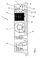
- FIG. 1 shows an automatic transmission 1 with a drive portion 2, a hydrodynamic converter 3 and a driven portion 4.
- the automatic transmission 1 an electric machine 5 on.
- the drive portion 2 of the automatic transmission 1 is exemplified in the representation selected here and corresponds to the structure which from the German patent application DE 10 2008 010 064 is basically known.
- This in FIG. 1 shown construction of the drive section 2 is to be understood only as an example, since the basic idea of the invention works with any type of drive section 2, which realizes a power split in at least two power branches.
- the two power branches are once a power branch, which runs over the hydrodynamic converter 3 and parallel thereto a power branch 6, which runs purely mechanically coupled parallel to the power branch through the hydrodynamic converter 3.
- These two power branches are doing in the output area. 4 brought together again via a suitable gear 7.
- the representation of the output section 4 and the automatic transmission 1 is to be understood only as an example, the functionality basically corresponds to that in the German application DE 10 2008 027 946 is described.
- a conventional structure with typically two planetary gear sets in the output range would be conceivable.
- the above-mentioned electrical machine 5 is additionally present.
- the electric machine 5 is integrated into the housing of the automatic transmission 1, so that a compact structure is created.
- the electric machine 5 acts in the embodiment of FIG. 1 to an output 8 of the automatic transmission 1.
- the electric machine 5 with the web 9 of the transmission 8 designed as a planetary gear of the output portion 4 is firmly connected. Also fixed to this web 9, the purely mechanical power branch 6 is connected.
- the electric machine 1 can be used as a motor or generator which either converts electrical energy into propulsion power or converts braking energy back into electrical energy.
- pure to brakes on the converter 3 as a seal-free retarder can be realized with the electric machine 5 braking to a standstill.
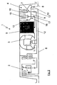
- FIG. 2 an alternative embodiment of the automatic transmission 1 is shown.
- the output region 4 has an additional planetary gearset 16 on, which is connected via a common web 9 with the planetary gear set 7 and with the purely mechanical power branch 6.
- the additional planetary gearset 16 would be, for example, the third planetary gearset.
- the power branch is coupled in via the hydrodynamic converter 3 via the planetary gear 7 and here in particular via the sun 13 thereof.
- the electric machine 5 is coupled via the additional planetary gear 16, wherein the electric machine 5 is also connected to the sun 17 of this planetary gear 16.
- This construction in which the electric machine 5 and the hydrodynamic converter are coupled in each case via its own gearbox in the output region 4, makes it possible to make the structure even more variable, since different translations for the electric machine 5 and the power branch via the hydrodynamic converter 3 can be selected.
- Both gears 7, 16 are controlled via multi-plate clutches 18, 19 so that they can be switched accordingly by pressing or non-actuation, so that either the electric machine 5 and the hydrodynamic converter 3 are coupled, or that in each case only one of the elements or none the elements is coupled into the output area 4.
- a clutch in particular a multi-plate clutch, which is not shown here, is provided, which is arranged between the web 9 and the sun 17 of the planetary gearset 16.
- This construction makes it possible to couple the electric machine 5 to the output 8.
- This variability of a second translation, in particular a 1: 1 ratio makes it possible to drive less effort in the design of the electric machine 5, since here reduces the required speed spread by the additional ratio, or alternatively, the achievable speed can be increased.
- the electric Machine 5 can thus be better optimized to a smaller operating range, so that the electrical machine 5 can be optimized in terms of constructive aspects and thus made more economical and energy efficient. Thus, an electric machine with a lower maximum speed can be used.
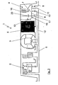
- FIG. 3 again shows a similar configuration as in FIG. 2 , but here only a multi-plate clutch 18 is present, so that only the hydrodynamic converter 3 is correspondingly switchable, while the electric machine 5 remains firmly coupled.
- both gear 7, 16 could be fixedly coupled without multi-plate clutch, or alternatively, only the additional gear 16 would have a multi-plate clutch 19, but not the transmission 7 for the power branch via the hydrodynamic converter 3.
- Analogous to the comments on FIG. 2 would be conceivable in the embodiment of Figure 6 on the multi-plate clutch 15, not shown here, the direct connection of the common web 9 with the sun 17 of the planetary gear 16 so that a direct 1: 1 coupling of the electric machine 5 to the output 8 is possible.
- FIG. 4 is now a structure analogous to the FIG. 3 to recognize.
- the only difference here is that the coupling of the electric machine does not take place via the sun 17 of the planetary gear 16, but via a ring gear 20 thereof.
- the ring gear 20 fixedly connected to the housing of the automatic transmission 1, so now the sun 17 is firmly connected to the housing of the automatic transmission 1.
- the electric machine 5 is coupled via the ring gear 20.
- the other structure corresponds to that of the previous figure. in principle, this should be in FIG. 4 illustrated embodiment show that in all the described arrangements and structures shown with planetary gears the constellation shown in each case is to be understood by way of example.
Landscapes
- Engineering & Computer Science (AREA)
- General Engineering & Computer Science (AREA)
- Mechanical Engineering (AREA)
- Chemical & Material Sciences (AREA)
- Combustion & Propulsion (AREA)
- Transportation (AREA)
- Arrangement Of Transmissions (AREA)
- Structure Of Transmissions (AREA)
Description
- Die Erfindung betrifft ein Automatgetriebe mit hydrodynamischem Wandler, welches einen Antriebsbereich aufweist, in welchem die Leistung in wenigstens zwei Leistungszweige aufteilbar ist, wobei ein Leistungszweig über den hydrodynamischen Wandler verläuft, und welches einen Abtriebsbereich aufweist, in welchem die wenigstens zwei Leistungszweige zusammenführbar sind.
- Automatgetriebe mit hydrodynamischem Wandler sind aus dem Stand der Technik bekannt. Sie weisen im Allgemeinen einen verzweigten Leistungsfluss auf, bei welchem ein Teil der Leistung in bestimmten Betriebszuständen über den hydrodynamischen Wandler verläuft, während ein anderer Teil der Leistung parallel dazu über einen mechanisch gekoppelten Leistungszweig, welcher typischerweise Getriebeelemente aufweist, verläuft.
- Ein Automatgetriebe mit den Merkmalen im Oberbegriff des Anspruchs 1 zeigt die
US 2002/193200 A1 . - Aus der
DE 101 52 488 A1 ist ferner eine Antriebsvorrichtung für ein Fahrzeug bekannt, in welchem eine Wandlergetriebebaueinheit mit einer elektrischen Maschine kombiniert wird. Die elektrische Maschine wird über Elektrizität aus einem Generator angetrieben und ist mittelbar mit den Rädern des Fahrzeuges gekoppelt, wobei die Kopplung eine Getriebeeinheit mit dem hydrodynamischen Wandler vorsieht. Der Aufbau ist dabei prinzipiell ein klassischer serieller Hybridantrieb, bei dem über einen Verbrennungsmotor und einen Generator elektrische Energie erzeugt wird, welche dann über einen Elektromotor zum Antrieb genutzt wird. Da bei klassischen Hybridantrieben die elektrische Antriebsmaschine im Falle des Abbremsens des Fahrzeugs als Generator genutzt wird, besteht somit bei hybriden Antriebssystemen die Möglichkeit, Energie beim Bremsen rückzugewinnen. - Der beschriebene Aufbau hat jedoch den Nachteil, dass aufgrund der Kopplung über den hydrodynamischen Wandler kein Abbremsen über den Antriebsmotor im generatorischen Betrieb bis zum Stillstand möglich ist, sodass Energie verloren geht, die prinzipiell zurückgewonnen werden könnte.
- Zum weiteren Stand der Technik wird auf die
WO 02/085659 A1 DE 10 2007 001 840 A1 verwiesen. - Es ist die Aufgabe der vorliegenden Erfindung ein Automatgetriebe mit hydrodynamischem Wandler zu hybridisieren und hinsichtlich der Hybridisierung zu optimieren.
- Erfindungsgemäß wird diese Aufgabe dadurch gelöst, dass zusätzlich eine elektrische Maschine mit dem Abtriebsbereich gekoppelt ist.
- Der Abtriebsbereich des Automatgetriebes dient üblicherweise der Zusammenführung der zuvor verzweigten Leistungen, um diese dem Abtrieb zur Verfügung zu stellen. Üblicherweise kann dazu ein Leistungsstrang direkt mechanisch und ein Leistungsstrang über den hydrodynamischen Wandler übertragen werden. Diese beiden Leistungsstränge werden im Abtriebsbereich zusammengeführt. Der Antrieb des Automatgetriebes selbst kann dabei über beliebige Leistungsquellen erfolgen. Typischerweise wird hier jedoch zumeist eine Brennkraftmaschine verwendet werden.
- Erfindungsgemäß ist nun zusätzlich eine elektrische Maschine mit dem Abtriebsbereich gekoppelt. Die Kopplung der elektrischen Maschine mit dem Abtriebsbereich erlaubt es somit Energie unmittelbar in den Abtrieb einzuspeisen oder im Falle von überschüssiger Energie im Abtrieb (beim Bremsen) diese mit der elektrischen Maschine im generatorischen Betrieb wieder in nutzbare elektrische Energie zurückzuwandeln. Durch die Einbindung der elektrischen Maschine in den Abtriebsbereich kann diese anstelle des oder zusammen mit dem hydrodynamischen Wandler Leistung alternativ zu - oder parallel zu - dem mechanischen Leistungszweig an den Abtrieb des Automatgetriebes liefern. Eine Betriebsweise könnte zum Beispiel sein, den Wandler beim Anfahren im 1. Gang mit der elektrischen Maschine zu unterstützen. Im weiteren Verlauf des Betriebes, das heißt im 2. und höheren Gängen, erfolgt der Vortrieb nur noch über mechanischen Leistungszweig, wobei die elektrische Maschine ggf. bei Beschleunigungsvorgängen unterstützend eingreifen und Leistung bereitstellen kann. Beim Abbremsen aus höheren Drehzahlen und eher hohen Bremsleistungen kann dann auch über den Wandler gebremst werden. Die elektrische Maschine kann dabei ggf. unterstützend eingreifen. Beim weiteren beziehungsweise normalen Abbremsen bis zum Stillstand, was mit dem Wandler alleine nicht möglich wäre kann dann in besonders vorteilhafter Weise die elektrische Maschine genutzt werden.
- Gemäß der Erfindung ist dabei die elektrische Maschine direkt mit dem mechanischen Leistungszweig ohne den hydrodynamischen Wandler gekoppelt Dies ermöglicht einen einfachen und kompakten Aufbau, bei der die elektrische Maschine durch die direkte Einbindung sowohl im Antriebsfall als auch im Bremsfall effektiv genutzt werden kann.
- Gemäß einer besonders günstigen Ausführungsform der vorliegenden Erfindung erfolgt die Kopplung der elektrischen Maschine dabei über ein Getriebeelement.
- Das Getriebeelement, welches beispielsweise als Planetengetriebe ausgebildet sein kann, erlaubt es, die elektrische Maschine mit einer wählbaren oder festen Übersetzung in den Abtriebsbereich einzukoppeln, sodass die Auswahl der elektrischen Maschine flexibler gestaltet werden kann. So ist beispielsweise eine geringere Spreizung der Drehzahl bei der elektrischen Maschine möglich, wenn diese über ein Getriebeelement mit geeigneter oder - bei wählbaren Übersetzungen - mit geeigneten Übersetzung(en) in den Abtriebsbereich eingekoppelt werden kann. Außerdem erlaubt es diese Konstellation, höhere Abtriebs-Drehzahlen zu realisieren.
- Gemäß einer besonders günstigen Weiterbildung der Erfindung ist es außerdem vorgesehen, dass die elektrische Maschine über ein Kupplungselement vom Abtriebsbereich entkoppelbar ist.
- Diese Entkopplung der elektrischen Maschine, welche beispielsweise über eine Lamellenkupplung erfolgen kann, erlaubt es, die elektrische Maschine vollkommen abzukoppeln, sodass ein Aufbau entsteht, welcher einem herkömmlichen Getriebe mit hydrodynamischem Wandler vergleichbar ist. Damit besteht dann die vorteilhafte Möglichkeit zwischen einem hybridisierten Betrieb und einem herkömmlichen Betrieb zu wählen.
- Gemäß einer sehr vorteilhaften Variante der Erfindung ist es ferner vorgesehen, dass die elektrische Maschine über eine Kupplung direkt mit dem Abtrieb koppelbar ist.
- Durch die direkte Kopplung des Abtriebs des Automatgetriebes mit der elektrischen Maschine wird eine Übersetzung von 1:1 im Abtrieb erreicht. Dementsprechend muss die elektrische Maschine keine hohe Maximaldrehzahl aufweisen und kann damit besonders kostengünstig, energieeffizient, robust und platzsparend ausgelegt werden.
- In einer sehr günstigen und vorteilhaften Ausgestaltung des erfindungsgemäßen Automatgetriebes ist es dabei vorgesehen, dass der Abtriebsbereich lediglich ein Planetengetriebe mit fester Kopplungsstruktur aufweist.
- Dieser Aufbau, bei dem im Abtriebsbereich des Automatgetriebes lediglich ein Planetengetriebe mit fester Kopplungsstruktur angeordnet ist, erlaubt es, das Automatgetriebe sehr einfach, mit wenigen Bauteilen und damit besonders kostengünstig herzustellen. Der Aufbau ist außerdem extrem kompakt zu realisieren, sodass Bauraum eingespart wird, welcher beispielsweise durch die elektrische Maschine genutzt werden könnte. Der Nachteil bei diesem Aufbau liegt nun darin, dass über den mechanischen beziehungsweise den mechanisch/hydrodynamischen Leistungsstrang kein Rückwärtsgang realisiert werden kann, da die Kopplungsstruktur im Abtriebsbereich nicht veränderbar ist. Aufgrund der elektrischen Maschine kann jedoch ein Rückwärtsgang sehr einfach und effizient über die elektrische Maschine realisiert werden, sodass die fehlende Möglichkeit zur Änderung der Kopplungsstruktur keinen nennenswerten Einfluss auf die Funktionalität des erfindungsgemäßen Automatgetriebes hat. Ohne eine Einbuße an Funktionalität kann jedoch der Aufbau entsprechend einfach und kompakt realisiert werden.
- Gemäß einer vorteilhaften Weiterbildung der Erfindung ist die elektrische Maschine ist dabei in das Gehäuse des Automatgetriebes integriert.
- Damit entsteht ein sehr kompakter Aufbau des Automatgetriebes. Dieser Aufbau kann es außerdem ermöglichen, das Automatgetriebe beziehungsweise dessen Gehäuse hinsichtlich seiner äußeren Abmessungen so zu gestalten, dass eine hybridisierte Version durch einen ähnlichen Bauraumbedarf gegen eine herkömmliche ausgetauscht werden kann. Somit wird fahrzeugseitig ein modularer Aufbau möglich, in dem mit minimalem Aufwand und bei unverändertem Chassis eine Hybridisierung ergänzbar oder nachrüstbar ist.
- Weitere vorteilhafte Ausgestaltungen der Erfindung ergeben sich aus den nachfolgend anhand der Zeichnungen dargestellten Ausführungsbeispielen.
- Dabei zeigen:
- Figur 1
- eine erste Ausführungsform des erfindungsgemäßen Automatgetriebes;
- Figur 2
- eine weitere Ausführungsform des erfindungsgemäßen Automatgetriebes in einer ersten Ausgestaltung;
- Figur 3
- die Ausführungsform gemäß
Figur 2 in einer alternativen Ausgestaltung; und - Figur 4
- die Ausführungsform gemäß
Figur 2 in einer weiteren alternativen Ausgestaltung. -
Figur 1 zeigt ein Automatgetriebe 1 mit einem Antriebsbereich 2, einem hydrodynamischen Wandler 3 und einem Abtriebsbereich 4. Zusätzlich weist das Automatgetriebe 1 eine elektrische Maschine 5 auf. Der Antriebsbereich 2 des Automatgetriebes 1 ist in der hier gewählten Darstellung beispielhaft ausgeführt und entspricht dem Aufbau, welcher aus der deutschen PatentanmeldungDE 10 2008 010 064 grundsätzlich bekannt ist. Dieser inFigur 1 dargestellte Aufbau des Antriebsbereichs 2 ist dabei jedoch nur beispielhaft zu verstehen, da die grundlegende Idee der Erfindung mit jeglicher Art von Antriebsbereich 2 funktioniert, welche eine Leistungsverzweigung in wenigstens zwei Leistungszweige realisiert. - In dem hier dargestellten Ausführungsbeispiel sind die beiden Leistungszweige einmal ein Leistungszweig, welcher über den hydrodynamischen Wandler 3 verläuft und parallel dazu ein Leistungszweig 6, welcher rein mechanisch gekoppelt parallel zu dem Leistungszweig durch den hydrodynamischen Wandler 3 verläuft. Diese beiden Leistungszweige werden dabei in dem Abtriebsbereich 4 über ein geeignetes Getriebe 7 wieder zusammengeführt. Auch hier ist die Darstellung des Abtriebsbereichs 4 und des Automatgetriebes 1 lediglich beispielhaft zu verstehen, wobei die Funktionalität grundlegend der entspricht, die in der deutschen Anmeldung
DE 10 2008 027 946 beschrieben ist. Alternativ dazu wäre auch eine herkömmlicher Aufbau mit typischerweise zwei Planetensätzen im Abtriebsbereich denkbar. - Zusätzlich zu dem bis hierher, bezüglich Antriebsbereich 2, hydrodynamischem Wandler 3 und Abtriebsbereich 4, bekannten Aufbau des Automatgetriebes 1 ist die oben bereits erwähnte elektrische Maschine 5 zusätzlich vorhanden. Die elektrische Maschine 5 ist dabei in das Gehäuse des Automatgetriebes 1 mit integriert, sodass eine kompakter Aufbau entsteht. Die elektrische Maschine 5 wirkt im Ausführungsbeispiel der
Figur 1 auf einen Abtrieb 8 des Automatgetriebes 1. Hierfür ist die elektrische Maschine 5 mit dem Steg 9 des als Planetengetriebe ausgebildeten Getriebes 8 des Abtriebsbereichs 4 fest verbunden. Ebenfalls fest mit diesem Steg 9 ist der rein mechanische Leistungszweig 6 verbunden. Durch geeignete Ansteuerung von Klauenkupplungen 10 und/oder der Lamellenkupplung 11 kann so die elektrische Maschine mit der Übersetzung 1:1 mit dem mechanischen Leistungszweig 6 zusammen/unterstützen oder falls der mechanische Leistungszweig 6 über eine geeignete Schaltung im Bereich des Antriebsbereichs 2 abgekoppelt ist, allein auf den Abtrieb 8 wirken. Je nachdem, ob Traktionsenergie am Abtrieb 8 erforderlich ist oder Bremsenergie am Abtrieb 8 anfällt, kann die elektrische Maschine 1 dabei als Motor oder Generator eingesetzt werden, welche entweder elektrische Energie in Vortriebsleistung umwandelt oder Bremsenergie zu elektrischer Energie zurückwandelt. Im Gegensatz reinen zum Bremsen über den Wandler 3 als verschließfreie Dauerbremse kann mit der elektrischen Maschine 5 ein Abbremsen bis zum Stillstand realisiert werden. - In
Figur 2 ist eine alternative Ausführungsform des Automatgetriebes 1 dargestellt. Der Abtriebsbereich 4 weist dabei einen zusätzlichen Planetensatz 16 auf, welcher über einen gemeinsamen Steg 9 mit dem Planetensatz 7 und mit dem rein mechanischen Leistungszweig 6 verbunden ist. Im Falle dass der Aufbau des Abtriebsbereichs 4 bereits mehr als einen Planetensatz aufweisen würde, zum Beispiel zwei Planetensätze - wie häufig üblich -, würde es sich bei dem zusätzlichen Planetensatz 16 dann beispielsweise um den 3. Planetensatz handeln. - Über das Planetengetriebe 7 und hier insbesondere über die Sonne 13 desselben wird wiederum der Leistungszweig über den hydrodynamischen Wandler 3 eingekoppelt. Die elektrische Maschine 5 ist über das zusätzliche Planetengetriebe 16 eingekoppelt, wobei die elektrische Maschine 5 ebenfalls mit der Sonne 17 dieses Planetengetriebes 16 verbunden ist. Dieser Aufbau, bei dem die elektrische Maschine 5 und der hydrodynamische Wandler jeweils über ein eigenes Getriebe in dem Abtriebsbereich 4 eingekoppelt werden, erlaubt es, den Aufbau noch variabler zu gestalten, da unterschiedliche Übersetzungen für die elektrische Maschine 5 und den Leistungszweig über den hydrodynamischen Wandler 3 gewählt werden können. Beide Getriebe 7, 16 sind dabei über Lamellenkupplungen 18, 19 so angesteuert, dass diese durch Betätigen beziehungsweise Nichtbetätigen entsprechend geschaltet werden können, sodass entweder die elektrische Maschine 5 und der hydrodynamische Wandler 3 eingekoppelt sind, oder dass jeweils nur eines der Elemente oder auch keines der Elemente in den Abtriebsbereich 4 eingekoppelt ist.
- Außerdem kann eine Kupplung, insbesondere eine Lamellenkupplung, welche hier nicht dargestellt ist, vorgesehen, welche zwischen dem Steg 9 und der Sonne 17 des Planetensatzes 16 angeordnet ist. Dieser Aufbau ermöglicht es, die der elektrischen Maschine 5 mit dem Abtrieb 8 zu koppeln. Diese Variabilität einer zweiten Übersetzung, insbesondere einer 1:1 Übersetzung ermöglicht es, bei der Auslegung der elektrischen Maschine 5 weniger Aufwand treiben zu müssen, da hier durch die zusätzliche Übersetzung die benötigte Drehzahlspreizung verringert, oder alternativ dazu, die erreichbare Drehzahl erhöht werden kann. Die elektrische Maschine 5 lässt sich so besser auf einen in sich kleineren Betriebsbereich optimieren, sodass die elektrische Maschine 5 hinsichtlich konstruktiver Aspekte optimiert und damit wirtschaftlicher und energieeffizienter gestaltet werden kann. Damit kann eine elektrische Maschine mit geringerer maximaler Drehzahl eingesetzt werden.
- Der Aufbau in
Figur 3 zeigt wiederum eine vergleichbare Ausgestaltung wie inFigur 2 , wobei hier jedoch lediglich eine Lamellenkupplung 18 vorhanden ist, sodass nur der hydrodynamische Wandler 3 entsprechend schaltbar ist, während die elektrische Maschine 5 fest eingekoppelt bleibt. - Ergänzend hierzu wären in nicht dargestellten Ausführungsformen weitere Aufbauten denkbar. So könnten zum Beispiel beide Getriebe 7, 16 ohne Lamellenkupplung fest gekoppelt sein, oder alternativ dazu lediglich das zusätzliche Getriebe 16 eine Lamellenkupplung 19 aufweisen würde, nicht jedoch das Getriebe 7 für den Leistungszweig über den hydrodynamischen Wandler 3. Analog zu den Ausführungen zu
Figur 2 wäre auch in der Ausführung der Figur 6 über die hier nicht dargestellte Lamellenkupplung 15 die direkte Verbindung des gemeinsamen Stegs 9 mit der Sonne 17 des Planetengetriebes 16 denkbar, sodass eine direkte 1:1-Ankopplung der elektrischen Maschine 5 an den Abtrieb 8 möglich wird. - In
Figur 4 ist nun ein Aufbau analog dem derFigur 3 zu erkennen. Der einzige Unterschied ist hier, dass die Einkopplung der elektrischen Maschine nicht über die Sonne 17 des Planetengetriebes 16 erfolgt, sondern über ein Hohlrad 20 desselben. War inFigur 3 das Hohlrad 20 fest mit dem Gehäuse des Automatgetriebes 1 verbunden, so ist nun die Sonne 17 fest mit dem Gehäuse des Automatgetriebes 1 verbunden. Die elektrische Maschine 5 ist über das Hohlrad 20 eingekoppelt. Der sonstige Aufbau entspricht dem der vorhergegangenen Figur. prinzipiell soll das inFigur 4 dargestellte Ausführungsbeispiel zeigen, dass bei allen beschriebenen Anordnungen und gezeigten Aufbauten mit Planetengetrieben die jeweils dargestellte Konstellation beispielhaft zu verstehen ist. Wie bei Planetengetrieben üblich, ist es grundsätzlich immer denkbar, entsprechende Kräfte über Sonne, Hohlrad, Steg einzukoppeln und/oder auszukoppeln. Diese Kopplungsschemen sind dabei, wie es dem Fachmann geläufig ist, untereinander austauschbar, ohne dass dies den grundlegenden Aufbau der hier dargestellten Ausführungsbeispiele verändert, da der erfindungsgemäße Gedanke auch mit jeder anderen denkbaren Kupplungsstruktur der hier dargestellten Planetensätze realisierbar wäre. Auch in der Darstellung des Automatgetriebes 1 gemäß Figur 7 wäre eine direkte Verbindung des Abtriebs 8 mit der elektrischen Maschine 5 denkbar. Auch hier müsste eine entsprechende Kopplung über die hier nicht dargestellte Kupplung 15 erfolgen. Anders als bei den beiden vorhergehenden Figuren müsste hier jedoch nicht die Sonne 17 mit dem gemeinsamen Steg 5 verbunden werden, sondern das Hohlrad 20 des Planetengetriebes 16.
Claims (6)
- Automatgetriebe mit hydrodynamischem Wandler (3), welches einen Antriebsbereich aufweist, in welchem die Leistung in wenigstens zwei Leistungszweige aufteilbar ist, wobei ein Leistungszweig (12) über den hydrodynamischen Wandler verläuft, und welches einen Abtriebsbereich (4) aufweist, in welchem die wenigstens zwei Leistungszweige zusammenführbar sind, wobei zusätzlich eine elektrische Maschine (5) mit dem Abtriebsbereich (4) gekoppelt ist,
dadurch gekennzeichnet, dass die elektrische Maschine (5) direkt mit dem wenigstens einem Leistungszweig (6) ohne den hydrodynamischen Wandler (3) gekoppelt ist. - Automatgetriebe nach Anspruch 1, dadurch gekennzeichnet, dass die Kopplung der elektrischen Maschine (5) über wenigstens ein Getriebeelement (7,16) erfolgt.
- Automatgetriebe nach Anspruch 1 oder 2, dadurch gekennzeichnet, dass die elektrische Maschine (5) über ein Kupplungselement (11,19) vom Abtriebsbereich entkoppelbar ist.
- Automatgetriebe nach einem der Ansprüche 3 bis 8, dadurch gekennzeichnet, dass der Abtriebsbereich (4) genau ein Planetengetriebe (7) mit fester Kopplungsstruktur aufweist.
- Automatgetriebe nach Anspruch 2 oder 3, dadurch gekennzeichnet, dass die elektrische Maschine (5) über eine Kupplung (15) direkt mit dem Abtrieb (8) des Abtriebsbereichs (4) koppelbar ist.
- Automatgetriebe nach einem der vorhergehenden Ansprüche, dadurch gekennzeichnet, dass die elektrische Maschine (5) in ein Gehäuse des Automatgetriebes (1) integriert ist.
Applications Claiming Priority (2)
| Application Number | Priority Date | Filing Date | Title |
|---|---|---|---|
| DE102008045584A DE102008045584A1 (de) | 2008-09-03 | 2008-09-03 | Automatgetriebe mit hydrodynamischem Wandler |
| PCT/EP2009/006370 WO2010025911A1 (de) | 2008-09-03 | 2009-09-03 | Automatgetriebe mit hydrodynamischem wandler |
Publications (2)
| Publication Number | Publication Date |
|---|---|
| EP2293955A1 EP2293955A1 (de) | 2011-03-16 |
| EP2293955B1 true EP2293955B1 (de) | 2012-03-07 |
Family
ID=41226939
Family Applications (1)
| Application Number | Title | Priority Date | Filing Date |
|---|---|---|---|
| EP09778291A Not-in-force EP2293955B1 (de) | 2008-09-03 | 2009-09-03 | Automatgetriebe mit hydrodynamischem wandler |
Country Status (5)
| Country | Link |
|---|---|
| US (1) | US20110179891A1 (de) |
| EP (1) | EP2293955B1 (de) |
| AT (1) | ATE548207T1 (de) |
| DE (1) | DE102008045584A1 (de) |
| WO (1) | WO2010025911A1 (de) |
Families Citing this family (7)
| Publication number | Priority date | Publication date | Assignee | Title |
|---|---|---|---|---|
| DE102011013923A1 (de) | 2011-03-14 | 2012-09-20 | Voith Patent Gmbh | Kraftfahrzeugantriebsstrang mit einem Parallelhybridsystem |
| BRPI1106964A8 (pt) * | 2011-12-20 | 2017-09-19 | Miranda Monteiro De Lima Alan | Transmissão automática inercial continuamente variável |
| DE102014212052A1 (de) * | 2014-06-24 | 2015-12-24 | Voith Patent Gmbh | Differentialwandlergetriebe |
| DE102014212060A1 (de) * | 2014-06-24 | 2015-12-24 | Voith Patent Gmbh | Differenzialwandlergetriebe |
| CN104534052B (zh) * | 2014-12-12 | 2016-10-19 | 吴志强 | 一种复合型箱磨式液力偶合器以及起动器 |
| DE102017114063A1 (de) * | 2017-06-26 | 2018-12-27 | Voith Patent Gmbh | Leistungsübertragungsvorrichtung und Verfahren zum Betreiben einer Leistungsübertragungsvorrichtung in einem Antriebsstrang zum drehzahlvariablen Antreiben einer Arbeitsmaschine |
| DE102021203655A1 (de) | 2021-04-14 | 2022-10-20 | Zf Friedrichshafen Ag | Elektrisches Antriebssystem und Kupplungsvorrichtung für eine Kopplung eines Antriebsstrangs mit einem hydrodynamischen Drehmomentwandler |
Family Cites Families (13)
| Publication number | Priority date | Publication date | Assignee | Title |
|---|---|---|---|---|
| DE1064824B (de) * | 1958-04-02 | 1959-09-03 | Rockwell G M B H | Getriebe, insbesondere fuer Kraftfahrzeuge |
| DE1181072B (de) * | 1961-04-18 | 1964-11-05 | Voith Gmbh J M | Hydrodynamisch mechanisches Getriebe fuer Kraftfahrzeuge |
| DE3627370A1 (de) * | 1986-08-12 | 1988-02-25 | Voith Gmbh J M | Hydrodynamischer drehmomentwandler |
| DE19621380A1 (de) * | 1996-05-28 | 1997-12-04 | Voith Turbo Kg | Wandlergetriebe, insbesondere Differentialwandlergetriebe |
| DE19923315B4 (de) * | 1999-05-21 | 2015-06-18 | Zf Friedrichshafen Ag | Antriebssystem für ein Kraftfahrzeug |
| DE19923316A1 (de) * | 1999-05-21 | 2000-11-23 | Zahnradfabrik Friedrichshafen | Antriebssystem für ein Kraftfahrzeug |
| WO2002085659A1 (de) | 2001-04-24 | 2002-10-31 | Voith Turbo Gmbh & Co. Kg | Antriebseinheit mit integriertem elektromotor |
| DE10120174A1 (de) * | 2001-04-24 | 2002-10-31 | Voith Turbo Kg | Antriebseinheit und Antriebssystem mit einer Antriebseinheit |
| US6551207B2 (en) | 2001-06-14 | 2003-04-22 | Sun T. Hong | Automatic multi-level transmission for a vehicle |
| DE10152488A1 (de) | 2001-10-24 | 2002-06-06 | Voith Turbo Kg | Antriebsvorrichtung für ein Fahrzeug, insbesondere dieselelektrische Antriebsordnung mit Wandlergetriebebaueinheit |
| DE102007001840A1 (de) | 2007-01-12 | 2008-07-17 | Voith Patent Gmbh | Hybridantrieb, insbesondere für ein Kraftfahrzeug |
| DE102008010064B4 (de) | 2008-02-20 | 2016-04-07 | Voith Patent Gmbh | Automatgetriebe mit wenigstens einem Planetensatz |
| DE102008027946A1 (de) | 2008-06-12 | 2009-12-24 | Voith Patent Gmbh | Automatgetriebe mit einem Antriebsbereich, einem hydrodynamischen Wandler, und einem Abtriebsbereich sowie Verfahren zum Bremsen bei hohen Drehzahlen |
-
2008
- 2008-08-01 US US12/737,658 patent/US20110179891A1/en not_active Abandoned
- 2008-09-03 DE DE102008045584A patent/DE102008045584A1/de not_active Withdrawn
-
2009
- 2009-09-03 EP EP09778291A patent/EP2293955B1/de not_active Not-in-force
- 2009-09-03 AT AT09778291T patent/ATE548207T1/de active
- 2009-09-03 WO PCT/EP2009/006370 patent/WO2010025911A1/de not_active Ceased
Also Published As
| Publication number | Publication date |
|---|---|
| DE102008045584A1 (de) | 2010-03-04 |
| WO2010025911A1 (de) | 2010-03-11 |
| US20110179891A1 (en) | 2011-07-28 |
| ATE548207T1 (de) | 2012-03-15 |
| EP2293955A1 (de) | 2011-03-16 |
Similar Documents
| Publication | Publication Date | Title |
|---|---|---|
| EP2651681B1 (de) | Hybridantrieb | |
| EP2293955B1 (de) | Automatgetriebe mit hydrodynamischem wandler | |
| EP2979001A1 (de) | Getriebe für ein kraftfahrzeug | |
| DE102013201744A1 (de) | Hybridisiertes Kraftfahrzeuggetriebe | |
| AT522931A1 (de) | Elektrisch angetriebene achsanordnung für ein fahrzeug | |
| DE102007004464A1 (de) | Hybridantriebsanordnung für ein Fahrzeug mit einem Antriebsstrang | |
| DE102017222705B4 (de) | Getriebe für ein Kraftfahrzeug | |
| DE102014208712B3 (de) | Getriebe für einen Hybridantriebsstrang eines Fahrzeugs | |
| DE102018215234A1 (de) | Getriebe für ein Kraftfahrzeug | |
| WO2019141561A1 (de) | Getriebe für ein kraftfahrzeug, kraftfahrzeugantriebsstrang und verfahren zu dessen betreiben | |
| DE102018219628A1 (de) | Getriebe für ein Kraftfahrzeug | |
| EP3736152A1 (de) | Antriebsstrang | |
| DE102013225212B4 (de) | Getriebe für ein Kraftfahrzeug | |
| WO2023017026A1 (de) | Getriebeeinheit und schaltverfahren zum schalten der getriebeeinheit | |
| DE102011003830B4 (de) | Hybridantrieb | |
| DE102018215232A1 (de) | Getriebe für ein Kraftfahrzeug | |
| DE102018217870A1 (de) | Getriebe für ein Kraftfahrzeug | |
| DE102019200966B4 (de) | Leistungsverzweigtes Kraftfahrzeuggetriebe | |
| DE102012007623B4 (de) | Motor-Getriebe-Einheit | |
| WO2020249272A1 (de) | Getriebe für ein kraftfahrzeug | |
| DE102019208550A1 (de) | Schienenfahrzeugantriebsstrang sowie Schienenfahrzeug | |
| DE102008045583B4 (de) | Automatgetriebe mit Drehmomentwandler | |
| DE102021208626B4 (de) | Getriebevorrichtung für einen Hybridantriebsstrang für ein Kraftfahrzeug und Kraftfahrzeug mit einer solchen | |
| DE102013226963A1 (de) | Getriebe | |
| DE102013225207B4 (de) | Getriebe für ein Kraftfahrzeug |
Legal Events
| Date | Code | Title | Description |
|---|---|---|---|
| PUAI | Public reference made under article 153(3) epc to a published international application that has entered the european phase |
Free format text: ORIGINAL CODE: 0009012 |
|
| 17P | Request for examination filed |
Effective date: 20110114 |
|
| AK | Designated contracting states |
Kind code of ref document: A1 Designated state(s): AT BE BG CH CY CZ DE DK EE ES FI FR GB GR HR HU IE IS IT LI LT LU LV MC MK MT NL NO PL PT RO SE SI SK SM TR |
|
| AX | Request for extension of the european patent |
Extension state: AL BA RS |
|
| GRAP | Despatch of communication of intention to grant a patent |
Free format text: ORIGINAL CODE: EPIDOSNIGR1 |
|
| DAX | Request for extension of the european patent (deleted) | ||
| GRAS | Grant fee paid |
Free format text: ORIGINAL CODE: EPIDOSNIGR3 |
|
| GRAA | (expected) grant |
Free format text: ORIGINAL CODE: 0009210 |
|
| AK | Designated contracting states |
Kind code of ref document: B1 Designated state(s): AT BE BG CH CY CZ DE DK EE ES FI FR GB GR HR HU IE IS IT LI LT LU LV MC MK MT NL NO PL PT RO SE SI SK SM TR |
|
| REG | Reference to a national code |
Ref country code: GB Ref legal event code: FG4D Free format text: NOT ENGLISH |
|
| REG | Reference to a national code |
Ref country code: CH Ref legal event code: EP Ref country code: AT Ref legal event code: REF Ref document number: 548207 Country of ref document: AT Kind code of ref document: T Effective date: 20120315 |
|
| REG | Reference to a national code |
Ref country code: IE Ref legal event code: FG4D Free format text: LANGUAGE OF EP DOCUMENT: GERMAN |
|
| REG | Reference to a national code |
Ref country code: DE Ref legal event code: R096 Ref document number: 502009002988 Country of ref document: DE Effective date: 20120503 |
|
| REG | Reference to a national code |
Ref country code: NL Ref legal event code: VDEP Effective date: 20120307 |
|
| PG25 | Lapsed in a contracting state [announced via postgrant information from national office to epo] |
Ref country code: NL Free format text: LAPSE BECAUSE OF FAILURE TO SUBMIT A TRANSLATION OF THE DESCRIPTION OR TO PAY THE FEE WITHIN THE PRESCRIBED TIME-LIMIT Effective date: 20120307 Ref country code: LT Free format text: LAPSE BECAUSE OF FAILURE TO SUBMIT A TRANSLATION OF THE DESCRIPTION OR TO PAY THE FEE WITHIN THE PRESCRIBED TIME-LIMIT Effective date: 20120307 Ref country code: HR Free format text: LAPSE BECAUSE OF FAILURE TO SUBMIT A TRANSLATION OF THE DESCRIPTION OR TO PAY THE FEE WITHIN THE PRESCRIBED TIME-LIMIT Effective date: 20120307 Ref country code: NO Free format text: LAPSE BECAUSE OF FAILURE TO SUBMIT A TRANSLATION OF THE DESCRIPTION OR TO PAY THE FEE WITHIN THE PRESCRIBED TIME-LIMIT Effective date: 20120607 |
|
| LTIE | Lt: invalidation of european patent or patent extension |
Effective date: 20120307 |
|
| PG25 | Lapsed in a contracting state [announced via postgrant information from national office to epo] |
Ref country code: FI Free format text: LAPSE BECAUSE OF FAILURE TO SUBMIT A TRANSLATION OF THE DESCRIPTION OR TO PAY THE FEE WITHIN THE PRESCRIBED TIME-LIMIT Effective date: 20120307 Ref country code: LV Free format text: LAPSE BECAUSE OF FAILURE TO SUBMIT A TRANSLATION OF THE DESCRIPTION OR TO PAY THE FEE WITHIN THE PRESCRIBED TIME-LIMIT Effective date: 20120307 Ref country code: GR Free format text: LAPSE BECAUSE OF FAILURE TO SUBMIT A TRANSLATION OF THE DESCRIPTION OR TO PAY THE FEE WITHIN THE PRESCRIBED TIME-LIMIT Effective date: 20120608 |
|
| PG25 | Lapsed in a contracting state [announced via postgrant information from national office to epo] |
Ref country code: CY Free format text: LAPSE BECAUSE OF FAILURE TO SUBMIT A TRANSLATION OF THE DESCRIPTION OR TO PAY THE FEE WITHIN THE PRESCRIBED TIME-LIMIT Effective date: 20120307 |
|
| PG25 | Lapsed in a contracting state [announced via postgrant information from national office to epo] |
Ref country code: SE Free format text: LAPSE BECAUSE OF FAILURE TO SUBMIT A TRANSLATION OF THE DESCRIPTION OR TO PAY THE FEE WITHIN THE PRESCRIBED TIME-LIMIT Effective date: 20120307 Ref country code: SI Free format text: LAPSE BECAUSE OF FAILURE TO SUBMIT A TRANSLATION OF THE DESCRIPTION OR TO PAY THE FEE WITHIN THE PRESCRIBED TIME-LIMIT Effective date: 20120307 Ref country code: RO Free format text: LAPSE BECAUSE OF FAILURE TO SUBMIT A TRANSLATION OF THE DESCRIPTION OR TO PAY THE FEE WITHIN THE PRESCRIBED TIME-LIMIT Effective date: 20120307 Ref country code: PL Free format text: LAPSE BECAUSE OF FAILURE TO SUBMIT A TRANSLATION OF THE DESCRIPTION OR TO PAY THE FEE WITHIN THE PRESCRIBED TIME-LIMIT Effective date: 20120307 Ref country code: IS Free format text: LAPSE BECAUSE OF FAILURE TO SUBMIT A TRANSLATION OF THE DESCRIPTION OR TO PAY THE FEE WITHIN THE PRESCRIBED TIME-LIMIT Effective date: 20120707 Ref country code: CZ Free format text: LAPSE BECAUSE OF FAILURE TO SUBMIT A TRANSLATION OF THE DESCRIPTION OR TO PAY THE FEE WITHIN THE PRESCRIBED TIME-LIMIT Effective date: 20120307 Ref country code: EE Free format text: LAPSE BECAUSE OF FAILURE TO SUBMIT A TRANSLATION OF THE DESCRIPTION OR TO PAY THE FEE WITHIN THE PRESCRIBED TIME-LIMIT Effective date: 20120307 |
|
| PG25 | Lapsed in a contracting state [announced via postgrant information from national office to epo] |
Ref country code: SK Free format text: LAPSE BECAUSE OF FAILURE TO SUBMIT A TRANSLATION OF THE DESCRIPTION OR TO PAY THE FEE WITHIN THE PRESCRIBED TIME-LIMIT Effective date: 20120307 Ref country code: PT Free format text: LAPSE BECAUSE OF FAILURE TO SUBMIT A TRANSLATION OF THE DESCRIPTION OR TO PAY THE FEE WITHIN THE PRESCRIBED TIME-LIMIT Effective date: 20120709 |
|
| PLBE | No opposition filed within time limit |
Free format text: ORIGINAL CODE: 0009261 |
|
| STAA | Information on the status of an ep patent application or granted ep patent |
Free format text: STATUS: NO OPPOSITION FILED WITHIN TIME LIMIT |
|
| PG25 | Lapsed in a contracting state [announced via postgrant information from national office to epo] |
Ref country code: DK Free format text: LAPSE BECAUSE OF FAILURE TO SUBMIT A TRANSLATION OF THE DESCRIPTION OR TO PAY THE FEE WITHIN THE PRESCRIBED TIME-LIMIT Effective date: 20120307 |
|
| 26N | No opposition filed |
Effective date: 20121210 |
|
| PG25 | Lapsed in a contracting state [announced via postgrant information from national office to epo] |
Ref country code: IT Free format text: LAPSE BECAUSE OF FAILURE TO SUBMIT A TRANSLATION OF THE DESCRIPTION OR TO PAY THE FEE WITHIN THE PRESCRIBED TIME-LIMIT Effective date: 20120307 |
|
| BERE | Be: lapsed |
Owner name: VOITH PATENT G.M.B.H. Effective date: 20120930 |
|
| REG | Reference to a national code |
Ref country code: DE Ref legal event code: R097 Ref document number: 502009002988 Country of ref document: DE Effective date: 20121210 |
|
| PG25 | Lapsed in a contracting state [announced via postgrant information from national office to epo] |
Ref country code: ES Free format text: LAPSE BECAUSE OF FAILURE TO SUBMIT A TRANSLATION OF THE DESCRIPTION OR TO PAY THE FEE WITHIN THE PRESCRIBED TIME-LIMIT Effective date: 20120618 Ref country code: MC Free format text: LAPSE BECAUSE OF NON-PAYMENT OF DUE FEES Effective date: 20120930 |
|
| REG | Reference to a national code |
Ref country code: IE Ref legal event code: MM4A |
|
| REG | Reference to a national code |
Ref country code: FR Ref legal event code: ST Effective date: 20130531 |
|
| PG25 | Lapsed in a contracting state [announced via postgrant information from national office to epo] |
Ref country code: BG Free format text: LAPSE BECAUSE OF FAILURE TO SUBMIT A TRANSLATION OF THE DESCRIPTION OR TO PAY THE FEE WITHIN THE PRESCRIBED TIME-LIMIT Effective date: 20120607 Ref country code: BE Free format text: LAPSE BECAUSE OF NON-PAYMENT OF DUE FEES Effective date: 20120930 Ref country code: IE Free format text: LAPSE BECAUSE OF NON-PAYMENT OF DUE FEES Effective date: 20120903 |
|
| PG25 | Lapsed in a contracting state [announced via postgrant information from national office to epo] |
Ref country code: FR Free format text: LAPSE BECAUSE OF NON-PAYMENT OF DUE FEES Effective date: 20121001 |
|
| PG25 | Lapsed in a contracting state [announced via postgrant information from national office to epo] |
Ref country code: MT Free format text: LAPSE BECAUSE OF FAILURE TO SUBMIT A TRANSLATION OF THE DESCRIPTION OR TO PAY THE FEE WITHIN THE PRESCRIBED TIME-LIMIT Effective date: 20120307 |
|
| PGFP | Annual fee paid to national office [announced via postgrant information from national office to epo] |
Ref country code: DE Payment date: 20130930 Year of fee payment: 5 |
|
| PG25 | Lapsed in a contracting state [announced via postgrant information from national office to epo] |
Ref country code: TR Free format text: LAPSE BECAUSE OF FAILURE TO SUBMIT A TRANSLATION OF THE DESCRIPTION OR TO PAY THE FEE WITHIN THE PRESCRIBED TIME-LIMIT Effective date: 20120307 |
|
| REG | Reference to a national code |
Ref country code: CH Ref legal event code: PL |
|
| GBPC | Gb: european patent ceased through non-payment of renewal fee |
Effective date: 20130903 |
|
| PG25 | Lapsed in a contracting state [announced via postgrant information from national office to epo] |
Ref country code: SM Free format text: LAPSE BECAUSE OF FAILURE TO SUBMIT A TRANSLATION OF THE DESCRIPTION OR TO PAY THE FEE WITHIN THE PRESCRIBED TIME-LIMIT Effective date: 20120307 Ref country code: LU Free format text: LAPSE BECAUSE OF NON-PAYMENT OF DUE FEES Effective date: 20120903 |
|
| PG25 | Lapsed in a contracting state [announced via postgrant information from national office to epo] |
Ref country code: GB Free format text: LAPSE BECAUSE OF NON-PAYMENT OF DUE FEES Effective date: 20130903 Ref country code: CH Free format text: LAPSE BECAUSE OF NON-PAYMENT OF DUE FEES Effective date: 20130930 Ref country code: HU Free format text: LAPSE BECAUSE OF FAILURE TO SUBMIT A TRANSLATION OF THE DESCRIPTION OR TO PAY THE FEE WITHIN THE PRESCRIBED TIME-LIMIT Effective date: 20090903 Ref country code: LI Free format text: LAPSE BECAUSE OF NON-PAYMENT OF DUE FEES Effective date: 20130930 |
|
| REG | Reference to a national code |
Ref country code: DE Ref legal event code: R119 Ref document number: 502009002988 Country of ref document: DE |
|
| REG | Reference to a national code |
Ref country code: DE Ref legal event code: R119 Ref document number: 502009002988 Country of ref document: DE Effective date: 20150401 |
|
| PG25 | Lapsed in a contracting state [announced via postgrant information from national office to epo] |
Ref country code: MK Free format text: LAPSE BECAUSE OF FAILURE TO SUBMIT A TRANSLATION OF THE DESCRIPTION OR TO PAY THE FEE WITHIN THE PRESCRIBED TIME-LIMIT Effective date: 20120307 Ref country code: DE Free format text: LAPSE BECAUSE OF NON-PAYMENT OF DUE FEES Effective date: 20150401 |
|
| REG | Reference to a national code |
Ref country code: AT Ref legal event code: MM01 Ref document number: 548207 Country of ref document: AT Kind code of ref document: T Effective date: 20140903 |
|
| PG25 | Lapsed in a contracting state [announced via postgrant information from national office to epo] |
Ref country code: AT Free format text: LAPSE BECAUSE OF NON-PAYMENT OF DUE FEES Effective date: 20140903 |