EP2293982B1 - Treibstoffablasssystem - Google Patents
Treibstoffablasssystem Download PDFInfo
- Publication number
- EP2293982B1 EP2293982B1 EP08768873.5A EP08768873A EP2293982B1 EP 2293982 B1 EP2293982 B1 EP 2293982B1 EP 08768873 A EP08768873 A EP 08768873A EP 2293982 B1 EP2293982 B1 EP 2293982B1
- Authority
- EP
- European Patent Office
- Prior art keywords
- fuel
- conduit
- useable
- jettison
- recited
- Prior art date
- Legal status (The legal status is an assumption and is not a legal conclusion. Google has not performed a legal analysis and makes no representation as to the accuracy of the status listed.)
- Not-in-force
Links
Images

Classifications
-
- B—PERFORMING OPERATIONS; TRANSPORTING
- B64—AIRCRAFT; AVIATION; COSMONAUTICS
- B64D—EQUIPMENT FOR FITTING IN OR TO AIRCRAFT; FLIGHT SUITS; PARACHUTES; ARRANGEMENT OR MOUNTING OF POWER PLANTS OR PROPULSION TRANSMISSIONS IN AIRCRAFT
- B64D37/00—Arrangements in connection with fuel supply for power plant
- B64D37/02—Tanks
- B64D37/06—Constructional adaptations thereof
- B64D37/12—Constructional adaptations thereof jettisonable
-
- B—PERFORMING OPERATIONS; TRANSPORTING
- B64—AIRCRAFT; AVIATION; COSMONAUTICS
- B64D—EQUIPMENT FOR FITTING IN OR TO AIRCRAFT; FLIGHT SUITS; PARACHUTES; ARRANGEMENT OR MOUNTING OF POWER PLANTS OR PROPULSION TRANSMISSIONS IN AIRCRAFT
- B64D37/00—Arrangements in connection with fuel supply for power plant
- B64D37/02—Tanks
- B64D37/14—Filling or emptying
- B64D37/20—Emptying systems
- B64D37/26—Jettisoning of fuel
-
- Y—GENERAL TAGGING OF NEW TECHNOLOGICAL DEVELOPMENTS; GENERAL TAGGING OF CROSS-SECTIONAL TECHNOLOGIES SPANNING OVER SEVERAL SECTIONS OF THE IPC; TECHNICAL SUBJECTS COVERED BY FORMER USPC CROSS-REFERENCE ART COLLECTIONS [XRACs] AND DIGESTS
- Y02—TECHNOLOGIES OR APPLICATIONS FOR MITIGATION OR ADAPTATION AGAINST CLIMATE CHANGE
- Y02T—CLIMATE CHANGE MITIGATION TECHNOLOGIES RELATED TO TRANSPORTATION
- Y02T50/00—Aeronautics or air transport
- Y02T50/40—Weight reduction
Definitions
- the present invention relates to an aircraft fuel jettison system, and more particularly to an aircraft fuel jettison system which independently jettisons fuel from a multiple of fuel tanks to maintain equal aircraft balance.
- Aircraft often include provisions for the jettison of fuel to selectively reduce the overall weight of the aircraft. This may be necessitated in response to particular conditions.
- Fuel is conventionally jettisoned by a fuel jettison system with auxiliary jettison pumps and associated piping to pump fuel from the aircraft fuel tanks to an overboard location.
- auxiliary jettison pumps and associated piping to pump fuel from the aircraft fuel tanks to an overboard location.
- Such a system utilizes auxiliary pumps within each fuel tank which are not used for any other purpose and which comprise a significant load factor and installation expense.
- Conventional fuel jettison systems generally rely upon existing fuel tank quantity meters to determine the quantity of fuel which has been jettisoned.
- Document EP 1 731 422 A1 discloses an aircraft with an aerial refueling system and a fuel jettison function.
- a fuel jettison system generally includes an overboard fuel jettison conduit, a fuel pump, a fuel jettison conduit, a shutoff valve, and a dip conduit.
- the overboard fuel jettison conduit communicates jettisoned fuel from the fuel pump to an overboard location typically from an aft section of one of the sponsons.
- the shutoff valve is located in each fuel jettison conduit within the aircraft cabin sidewall.
- the shutoff valve is in communication with a fuel management control system for selective operation thereby.
- the shutoff valve is powered open by an actuator such as a solenoid valve and is closed in response to a mechanical bias.
- a manual actuator such as a lever accessible from within the aircraft cabin may also be utilized to overcome the bias and open the shutoff valve. Since the shutoff valves are located in the cabin sidewalls, they are accessible to crew should a malfunction occur.
- the shutoff valve includes an inward venting feature which permits the fuel jettison conduit to be vented such that the fuel pump may be operated to completely purge fuel from the fuel jettison conduit at the completion of a fuel jettison event to assure that all fuel downstream of the shutoff valve is purged from the fuel jettison system.
- the inward venting feature also facilitates ground support fuel pump checkout without having to actually jettison fuel which is advantageous in a shipboard environment.
- the fuel jettison system provides pilot-initiated automatic operation to jettison fuel down to, for example, a sixty (60) minute useable fuel remaining level.
- the fuel management control system communicates with fuel level probes of an FQGS to independently operate the shutoff valve such that aircraft balance is maintained. That is, the fuel jettison control system includes control algorithms which will independently operate each shutoff valve such that when each fuel tank separately reaches the sixty (60) minute useable fuel remaining level, the fuel management control system separately shuts the shutoff valve then purges that fuel jettison conduit. Pilot-initiated automatic operation is initiated by actuation of a fuel jettison switch.
- the fuel jettison system requires pilot-initiated manual operation to jettison further fuel down to a minimum, for example, twenty (20) minute useable fuel remaining level. This operation is achieved by holding the fuel jettison switch throughout the jettisoning operation to the minimum twenty (20) minute useable fuel remaining level. Since the bellmouth opening of the dip conduit is located at the minimum twenty (20) minute useable fuel remaining level, under no situation will the fuel jettison system jettison a quantity of fuel greater than this minimum twenty (20) minute useable fuel remaining level.
- the present invention therefore provides a fuel jettison system which provides independent jettisoning to a multiple of useable fuel remaining levels from a multiple of fuel tanks to maintain equal balance.
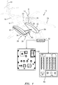
- FIG. 1 schematically illustrates a rotary- wing aircraft 10 having a main rotor system 12.
- the aircraft 10 includes an airframe 14 having an extending tail 16 which mounts a tail rotor system 18, such as an anti-torque system.
- the main rotor assembly 12 is driven about an axis of rotation R through a main gearbox (illustrated schematically at 20) by one or more engines 22.
- the main rotor system 12 includes a multiple of rotor blades 24 mounted to a rotor hub 26.
- helicopter configuration is illustrated and described in the disclosed embodiment, other configurations and/or machines, such as high speed compound rotary wing aircraft with supplemental translational thrust systems, dual contra-rotating, coaxial rotor system aircraft, turbo-props, tilt-rotors and tilt-wing aircraft, will also benefit from the present invention.
- the aircraft 10 includes a fuel system 28.
- the fuel system 28 generally includes a fuel management control system 30, a port main fuel tank 32 and a starboard main fuel tank 34 which communicate fuel to the engines 22.
- each fuel tank 32, 34 may generally contain a pressure refuel/defuel valve, fuel quantity and low-level sensors, high-level shutoff valves, low-level shutoff valves, check valve sump drains, as well as other fuel communication components (illustrated somewhat schematically at F in Figure 2 ) which need not be further described herein as such components are directed to communication of fuel to the engines 22.
- the port main fuel tank 32 and the starboard main fuel tank 34 are preferably located in sponsons 36, 38 mounted to a port and starboard side of the airframe 14. Both main fuel tanks are crashworthy, self-sealing and interchangeable. It should be understood that other fuel tank arrangements will benefit from the present invention, however, the illustrated arrangement is typical of a rotary wing aircraft.
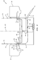
- the fuel system 28 further includes a fuel jettison system 40 ( Figure 2 ) to selectively jettison fuel from the main fuel tanks 32, 34 to a safe overboard location in response to the fuel management control system 30.
- a fuel jettison system 40 ( Figure 2 ) to selectively jettison fuel from the main fuel tanks 32, 34 to a safe overboard location in response to the fuel management control system 30.
- the fuel jettison system 40 is preferably independent of a fuel communication path from the main fuel tanks 32, 34 to the engines 22 to minimize unintentional fuel loss.
- each fuel tank within the fuel system 28 will include similar components.
- the fuel jettison system 40 generally includes an overboard fuel jettison conduit 42, a fuel pump 44, a fuel jettison conduit 46, a shutoff valve 48, a flex joint 50, a self sealing break away valve 52, a check valve 54 and a dip conduit 56.
- the overboard fuel jettison conduit 42 communicates jettisoned fuel from the fuel pump 44 to an overboard 58 location typically from an aft section of one of the sponsons 36, 38, here illustrated as the starboard sponson 38 ( Figure 2 ).
- the overboard fuel jettison conduit 42 penetrates a tub outer mold line 60 (illustrated schematically) of the airframe 14.
- the overboard fuel jettison conduit 42 includes a pressure sensor 62 which communicates with the fuel management control system 30 for confirmation of fuel pump 44 "on" operation.
- a condensation drain 64 may also be located within the overboard fuel jettison conduit 42 outboard of the tub outer mold line 60.
- the fuel pump 44 is preferably a 600 lb/min minimum pump 3-phase, 400 hz 5-hr run dry capability pump in communication with the fuel management control system 30.
- the fuel pump 44 is in communication with the overboard fuel jettison conduit 42 and the fuel jettison conduit 46.
- the fuel jettison conduit 46 communicates with an input to the fuel pump 44 at a fitting 66 such as the illustrated "Y" fitting which provides communication with each main fuel tanks 32, 34 through each of the respective fuel jettison conduits 46. It should be understood that any number of fuel jettison conduits 46 - one for each fuel tank - communicate with the fuel pump 44.
- the fuel pump 44 is preferably located below an aircraft cabin floor 68 generally along an aircraft centerline BL 0.0 such that the fuel jettison path from each main fuel tanks 32, 34 is generally of the same length.
- Each fuel jettison conduit 46 communicates between the fuel pump 44 and the respective fuel tank 32.
- the fuel jettison conduit 46 may pass through the aircraft cabin floor 68 and an aircraft cabin sidewall 70.
- the flex joint 50 is thereby located intermediate a cabin to sponson interface 72 adjacent the cabin sidewall 70 such that relevant movement of the sponsons 36, 38 relative the airframe 14 is accommodated thereby.
- the self sealing break away valve 52 is preferably located in the fuel jettison conduit 46 intermediate a frangible plane 74 which forms a portion of the cabin sidewall 70 such that the fuel jettison conduit 46 becomes sealed should the sponsons 36, 38 break away from the airframe 14.
- the shutoff valve 48 is preferably positioned within the aircraft cabin sidewall 70 and is in communication with the fuel management control system 30 for selective operation thereby.
- the shutoff valve 48 is powered open by an actuator 76 such as a solenoid and is closed in response to a mechanical spring bias. Should power be lost, the shutoff valve 48 is biased toward the closed position. That is, the shutoff valve 48 is biased to a closed position and requires power application such as application of 28V DC current controlled by the fuel management control system 30 to open.
- electrically powered components need not be located within the fuel tank with the fuel jettison system 40.
- a manual actuator 78 such as a lever accessible from within the aircraft cabin may also be operated to manually open the shutoff valve 48. Since the shutoff valves 48 are located in the cabin sidewalls 70, they are accessible to crew should such a need arise.
- the shutoff valve 48 also includes an inward venting feature which vents the fuel jettison conduit 46 to operate the fuel pump 44 after the shutoff valve 48 has closed to purge fuel from the fuel jettison conduit 46 at the completion of a fuel jettison event. This assures that all fuel downstream of the shutoff valve 48 is purged from the fuel jettison system 40.
- the inward venting feature also facilitates ground support fuel pump checkout without having to actually jettison fuel. This may be advantageous in a shipboard environment.
- the fuel jettison conduit 46 communicates with the dip conduit 56 located within the fuel tank 32.
- the dip conduit 56 includes a bellmouth opening 57 thereto at a minimum useable fuel remaining level which is preferably a twenty (20) minute useable fuel remaining level.
- the fuel jettison conduit 46 penetrates the fuel tank 32 at a relatively low waterline so as to minimize priming times (and total fuel jettison times).
- the dip conduit 56 penetrates into the fuel tank 32 at a level greater than the minimum useable fuel remaining level, for example, a sixty (60) minute useable fuel remaining level. It should be understood, however, that any useable fuel remaining levels may be utilized with the present invention and that the 20 minute and 60 minute time is for example only.
- the check valve 54 located within the dip conduit 56 assures that fuel will not be inadvertently jettisoned while the fuel pump 44 is in an "off' position.
- the fuel management control system 30 typically includes a processing module, such as a microprocessor and a memory device in communication therewith.
- the fuel management control system 30 stores data and control algorithms in the memory device or other suitable memory location.
- the control algorithms are the scheme by which the shut off valve 48 operational decisions are made.
- the fuel management control system 30 preferably utilizes the existing aircraft fuel quantity gauging system (FQGS) 80 ( Figure 1 ).
- the fuel jettison system 40 provides pilot-initiated automatic operation to jettison fuel down to the sixty (60) minute useable fuel remaining level.
- the fuel management control system 30 communicates with fuel level probes of the existing FQGS 80 to independently operate the shutoff valve 48 such that aircraft balance is maintained. That is, the fuel jettison system 40 includes control algorithms which will independently operate each shutoff valve 48 such that when each fuel tank 32, 34 reaches the sixty (60) minute useable fuel remaining level, the fuel management control system 30 shuts the shutoff valve 48 then purges that fuel jettison conduit 46.
- the pilot-initiated automatic operation is initiated by actuation of a fuel jettison switch 82 ( Figure 1 ).
- the fuel jettison system 40 requires pilot-initiated manual operation to jettison further fuel down to the minimum twenty (20) minute useable fuel remaining level.
- this operation is achieved by holding the fuel jettison switch 82 throughout the jettisoning operation from the sixty (60) minute useable fuel remaining level to the minimum twenty (20) minute useable fuel remaining level. Since the bellmouth opening 57 of the dip conduit is located at the minimum twenty (20) minute useable fuel remaining level, under no situation will the fuel jettison system 40 jettison a quantity of fuel greater than this minimum twenty (20) minute useable fuel remaining level.
- the fuel pump 44 is commanded closed after a time period such as 11 seconds after the FQGS 80 has detected the total fuel remaining quantity equivalent to 60 minute useable fuel remaining level in automatic operation and equivalent to 20 minute useable fuel remaining level in manual operation. That is, the shutoff valve 48 may be closed but the fuel pump may continue to operate until the time limit elapses.
Landscapes
- Engineering & Computer Science (AREA)
- Aviation & Aerospace Engineering (AREA)
- Cooling, Air Intake And Gas Exhaust, And Fuel Tank Arrangements In Propulsion Units (AREA)
Claims (15)
- Luftfahrzeug-Treibstoffablasssystem, umfassend:einen Treibstofftank (32, 34);eine Treibstoffpumpe (44);eine Treibstoffleitung (46), die mit dem Treibstofftank (32, 34) und der Treibstoffpumpe (44) in Verbindung steht;ein Absperrventil (48);und eine über Bord befindliche Treibstoffablassleitung (42), die mit der Treibstoffpumpe (44) in Verbindung steht, dadurch gekennzeichnet, dassdas Absperrventil (48) eine nach innen gerichtete Entlüftung innerhalb der Treibstoffleitung (46) aufweist, um den gesamten Treibstoff stromabwärts des Absperrventils (48) aus dem Treibstoffablasssystem (40) durch Betreiben der Treibstoffpumpe (44)auszustoßen, nachdem das Absperrventil (48) geschlossen wurde.
- System (40) nach Anspruch 1, wobei das Absperrventil (48) zwischen einer offenen Position und einer geschlossenen Position beweglich ist, wobei das Absperrventil (48) in die geschlossene Position vorgespannt ist.
- System (40) nach Anspruch 1 oder 2, ferner umfassend eine Treibstoffablasssteuerung (30), um das Treibstoffabsperrventil (48) als Reaktion auf ein Treibstoffmengenanzeigesystem unabhängig zu betreiben.
- System (40) nach einem der vorstehenden Ansprüche, ferner umfassend eine Tauchleitung (56), die mit der Treibstoffleitung in Verbindung steht, wobei die Tauchleitung (56) eine Öffnung bei einem ersten verwendbaren Treibstoffrestfüllstand innerhalb des Treibstofftanks (32, 34) definiert.
- System (40) nach Anspruch 4, wobei der erste verwendbare Treibstoffrestfüllstand innerhalb des Treibstofftanks (32, 34) ein zwanzigminütiger verwendbarer Treibstoffrestfüllstand ist.
- System (40) nach Anspruch 4 oder 5, wobei die Treibstoffleitung (46) auf einer zweiten Höhe in den Treibstofftank (32, 34) eindringt, die größer ist als der zwanzigminütige verwendbare Treibstoffrestfüllstand und kleiner als ein 120-minütiger verwendbarer Treibstoffrestfüllstand.
- System nach Anspruch 4 bis 6, wobei die Treibstoffleitung (46) bei einem etwa 60-minütigen verwendbaren Treibstoffrest in den Treibstofftank (32, 34) eindringt.
- System (40) nach einem der Ansprüche 4 bis 7, wobei die Tauchleitung (56) mit der Treibstoffleitung über ein selbstdichtendes Abreißventil in Verbindung steht.
- System (40) nach einem der vorstehenden Ansprüche, ferner umfassend eine Treibstoffablasssteuerung (30), die mit der Treibstoffpumpe (44) in Verbindung steht, wobei die Treibstoffablasssteuerung (30) einen vom Piloten initiierten automatischen Betrieb bis zu einem vordefinierten verwendbaren Treibstoffrestfüllstand und einen manuellen Betrieb zum Ablassen von Treibstoff bis zu einem verwendbaren Treibstoffrestfüllstand, der kleiner als der vordefinierte verwendbare Treibstoffrestfüllstand ist, bereitstellt.
- System (40) nach einem der Ansprüche 4, 5, 7, 8, 9, wobei die Treibstoffleitung auf eine zweiten Höhe in den Treibstofftank (32, 34) eindringt, die größer ist als die erste verwendbare Treibstoffrestfüllstand.
- Verfahren zum Ablassen von Treibstoff, umfassend die folgenden Schritte:A:) selektives Ablassen von Treibstoff auf einen vordefinierten verwendbaren Treibstoffrestfüllstand als Reaktion auf einen ersten Befehl; undB:) selektives Ablassen von Treibstoff auf einen verwendbaren Treibstoffrestfüllstand, der kleiner als der vordefinierte verwendbare Treibstoffrestfüllstand ist, als Reaktion auf einen zweiten Befehl,dadurch gekennzeichnet, dass
der Schritt des Ablassens das Schließen eines Absperrventils (48), das eine nach innen gerichtete Entlüftung innerhalb der Treibstoffleitung (46) aufweist, und das Ausstoßen des gesamten Treibstoffs stromabwärts des Absperrventils (48) aus dem Treibstoffablasssystem (40) durch Betreiben einer Treibstoffpumpe (44) umfasst. - Verfahren nach Anspruch 11, wobei der Schritt A ferner Folgendes umfasst: a:) das intermittierende Betätigen eines Schalters als ersten Befehl.
- Verfahren nach Anspruch 11 oder 12, wobei der Schritt B ferner Folgendes umfasst:a:) Halten des Schalters an der ersten Position als zweiter Befehl.
- Verfahren nach einem der Ansprüche 11 bis 13, wobei der Schritt B ferner Folgendes umfasst:
b:) Abschalten einer Treibstoffpumpe (44) als Reaktion auf das Loslassen des Schalters aus der ersten Position. - Verfahren nach Anspruch 14, wobei der Schritt A ferner Folgendes umfasst:a:) Schließen eines ersten Absperrventils in einer Treibstoffleitung zwischen einem ersten Treibstofftank und der Treibstoffpumpe als Reaktion auf das Erreichen des vordefinierten verwendbaren Treibstoffrestfüllstandes im ersten Treibstofftank;b:) Entlüften der ersten Treibstoffleitung nach dem Schritt a:);c:) Schließen eines zweiten Absperrventils in einer zweiten Treibstoffleitung zwischen einem zweiten Treibstofftank und der Treibstoffpumpe als Reaktion auf das Erreichen des vordefinierten verwendbaren Treibstoffrestfüllstandes im zweiten Treibstofftank unabhängig von dem Schritt a:); undd:) Entlüften der zweiten Treibstoffleitung nach dem Schritt c:).
Applications Claiming Priority (1)
| Application Number | Priority Date | Filing Date | Title |
|---|---|---|---|
| PCT/US2008/052149 WO2009096939A1 (en) | 2008-01-28 | 2008-01-28 | Fuel jettison system |
Publications (3)
| Publication Number | Publication Date |
|---|---|
| EP2293982A1 EP2293982A1 (de) | 2011-03-16 |
| EP2293982A4 EP2293982A4 (de) | 2013-09-11 |
| EP2293982B1 true EP2293982B1 (de) | 2018-12-12 |
Family
ID=40913075
Family Applications (1)
| Application Number | Title | Priority Date | Filing Date |
|---|---|---|---|
| EP08768873.5A Not-in-force EP2293982B1 (de) | 2008-01-28 | 2008-01-28 | Treibstoffablasssystem |
Country Status (2)
| Country | Link |
|---|---|
| EP (1) | EP2293982B1 (de) |
| WO (1) | WO2009096939A1 (de) |
Families Citing this family (2)
| Publication number | Priority date | Publication date | Assignee | Title |
|---|---|---|---|---|
| CN102673794B (zh) * | 2012-06-08 | 2015-08-26 | 中国航空工业集团公司西安飞机设计研究所 | 一种采用供油泵作为动力的空中放油装置 |
| CN111806706B (zh) * | 2020-07-07 | 2022-08-02 | 中国商用飞机有限责任公司 | 一种适用于飞机的储油系统以及该系统的应急放油方法 |
Family Cites Families (6)
| Publication number | Priority date | Publication date | Assignee | Title |
|---|---|---|---|---|
| GB417350A (en) * | 1933-07-11 | 1934-10-03 | Blackburn Aeroplane & Motor Co | Fuel jettisoning valve arrangement for aircraft |
| US4725022A (en) * | 1987-03-02 | 1988-02-16 | Wilform Jr Robert D | Fuel discarding device |
| US5746397A (en) * | 1996-06-14 | 1998-05-05 | Defield; Topper | Aircraft defueling system |
| US7111809B1 (en) * | 2004-06-18 | 2006-09-26 | The United States Of America As Represented By The Secretary Of The Navy | Aircraft excessive fuel dumping ejection parallel to flight direction |
| US7458543B2 (en) * | 2005-06-10 | 2008-12-02 | The Boeing Company | Aerial refueling system |
| KR100682396B1 (ko) * | 2006-11-23 | 2007-02-16 | 주식회사 뉴테크특장 | 항공기 급유차의 전자식 연료제어 시스템 |
-
2008
- 2008-01-28 EP EP08768873.5A patent/EP2293982B1/de not_active Not-in-force
- 2008-01-28 WO PCT/US2008/052149 patent/WO2009096939A1/en not_active Ceased
Non-Patent Citations (1)
| Title |
|---|
| None * |
Also Published As
| Publication number | Publication date |
|---|---|
| WO2009096939A1 (en) | 2009-08-06 |
| EP2293982A4 (de) | 2013-09-11 |
| EP2293982A1 (de) | 2011-03-16 |
Similar Documents
| Publication | Publication Date | Title |
|---|---|---|
| US7857260B2 (en) | Fuel jettison system | |
| US8226040B2 (en) | Continuous fuel management system for automatic control of aircraft center of gravity | |
| CN101140004B (zh) | 飞机动力系统和用于控制飞机系统的方法 | |
| US7337795B2 (en) | Fuel balancing system | |
| EP1765670B1 (de) | System zum betanken während des fluges und verfahren zur nottrennung von komponenten eines systems zum betanken während des fluges | |
| US9248912B2 (en) | Method and system for emergency ventilation of an aircraft cabin | |
| US20120064813A1 (en) | Cabin pressure thrust recovery outflow valve with single door | |
| EP4296158A1 (de) | Variable verkleidung für ein wasserstoff-kanalsystem und verwendungen desselben | |
| EP2517957B1 (de) | Luftbetankungssystem | |
| EP2074027B1 (de) | Treibstoffausgleichssystem | |
| US9487082B2 (en) | Aircraft fuel tank system | |
| EP2293982B1 (de) | Treibstoffablasssystem | |
| EP2877400B1 (de) | Durch schwimmerventile gesteuertes brennstofftransfersystem | |
| US8231082B2 (en) | Method and device for correcting the lateral dissymmetry of an aircraft | |
| EP3712069B1 (de) | Kabinendrucksteuerungssystem mit vollelektrischem ofv unter verwendung einer unterschiedlichen manuellen steuerung, die eine kabinenhöhenhaltefunktion ausführt | |
| US12291322B2 (en) | Drive system of an aircraft, aircraft and method for operating an aircraft | |
| US20250122839A1 (en) | Over-pressure vent system for an aircraft fuel tank | |
| US20120036866A1 (en) | Auxiliary power unit with multiple fuel sources | |
| US10472085B2 (en) | Differential pressure sensor system, aircraft equipped with a differential pressure sensor system and method for operating a differential pressure sensor system | |
| EP2565121B1 (de) | Kabinendruckablassventil mit Schubrückgewinnung und Verfahren zur RAM-Luftgewinnung | |
| Bruemmer et al. | Autonomous navigation system and method | |
| EP3623661B1 (de) | Schmiersystem | |
| US20200166120A1 (en) | Chemically Pressurized Emergency Lubrication System | |
| US20200166119A1 (en) | Emergency Lubrication System for Tiltrotor Aircraft | |
| EP4596420A1 (de) | Überdruckschutzsystem für ein flugzeug inline in einem sauerstoffarmen luftverteilungssystem |
Legal Events
| Date | Code | Title | Description |
|---|---|---|---|
| PUAI | Public reference made under article 153(3) epc to a published international application that has entered the european phase |
Free format text: ORIGINAL CODE: 0009012 |
|
| 17P | Request for examination filed |
Effective date: 20101214 |
|
| AK | Designated contracting states |
Kind code of ref document: A1 Designated state(s): AT BE BG CH CY CZ DE DK EE ES FI FR GB GR HR HU IE IS IT LI LT LU LV MC MT NL NO PL PT RO SE SI SK TR |
|
| AX | Request for extension of the european patent |
Extension state: AL BA MK RS |
|
| DAX | Request for extension of the european patent (deleted) | ||
| A4 | Supplementary search report drawn up and despatched |
Effective date: 20130814 |
|
| RIC1 | Information provided on ipc code assigned before grant |
Ipc: B64D 37/26 20060101AFI20130808BHEP Ipc: B64D 37/12 20060101ALI20130808BHEP |
|
| STAA | Information on the status of an ep patent application or granted ep patent |
Free format text: STATUS: EXAMINATION IS IN PROGRESS |
|
| 17Q | First examination report despatched |
Effective date: 20171013 |
|
| GRAP | Despatch of communication of intention to grant a patent |
Free format text: ORIGINAL CODE: EPIDOSNIGR1 |
|
| STAA | Information on the status of an ep patent application or granted ep patent |
Free format text: STATUS: GRANT OF PATENT IS INTENDED |
|
| INTG | Intention to grant announced |
Effective date: 20180629 |
|
| GRAS | Grant fee paid |
Free format text: ORIGINAL CODE: EPIDOSNIGR3 |
|
| GRAA | (expected) grant |
Free format text: ORIGINAL CODE: 0009210 |
|
| STAA | Information on the status of an ep patent application or granted ep patent |
Free format text: STATUS: THE PATENT HAS BEEN GRANTED |
|
| AK | Designated contracting states |
Kind code of ref document: B1 Designated state(s): AT BE BG CH CY CZ DE DK EE ES FI FR GB GR HR HU IE IS IT LI LT LU LV MC MT NL NO PL PT RO SE SI SK TR |
|
| REG | Reference to a national code |
Ref country code: GB Ref legal event code: FG4D |
|
| REG | Reference to a national code |
Ref country code: CH Ref legal event code: EP |
|
| REG | Reference to a national code |
Ref country code: AT Ref legal event code: REF Ref document number: 1075651 Country of ref document: AT Kind code of ref document: T Effective date: 20181215 |
|
| REG | Reference to a national code |
Ref country code: DE Ref legal event code: R096 Ref document number: 602008058316 Country of ref document: DE |
|
| REG | Reference to a national code |
Ref country code: IE Ref legal event code: FG4D |
|
| REG | Reference to a national code |
Ref country code: NL Ref legal event code: MP Effective date: 20181212 |
|
| REG | Reference to a national code |
Ref country code: LT Ref legal event code: MG4D |
|
| PG25 | Lapsed in a contracting state [announced via postgrant information from national office to epo] |
Ref country code: FI Free format text: LAPSE BECAUSE OF FAILURE TO SUBMIT A TRANSLATION OF THE DESCRIPTION OR TO PAY THE FEE WITHIN THE PRESCRIBED TIME-LIMIT Effective date: 20181212 Ref country code: LV Free format text: LAPSE BECAUSE OF FAILURE TO SUBMIT A TRANSLATION OF THE DESCRIPTION OR TO PAY THE FEE WITHIN THE PRESCRIBED TIME-LIMIT Effective date: 20181212 Ref country code: HR Free format text: LAPSE BECAUSE OF FAILURE TO SUBMIT A TRANSLATION OF THE DESCRIPTION OR TO PAY THE FEE WITHIN THE PRESCRIBED TIME-LIMIT Effective date: 20181212 Ref country code: NO Free format text: LAPSE BECAUSE OF FAILURE TO SUBMIT A TRANSLATION OF THE DESCRIPTION OR TO PAY THE FEE WITHIN THE PRESCRIBED TIME-LIMIT Effective date: 20190312 Ref country code: BG Free format text: LAPSE BECAUSE OF FAILURE TO SUBMIT A TRANSLATION OF THE DESCRIPTION OR TO PAY THE FEE WITHIN THE PRESCRIBED TIME-LIMIT Effective date: 20190312 Ref country code: LT Free format text: LAPSE BECAUSE OF FAILURE TO SUBMIT A TRANSLATION OF THE DESCRIPTION OR TO PAY THE FEE WITHIN THE PRESCRIBED TIME-LIMIT Effective date: 20181212 Ref country code: ES Free format text: LAPSE BECAUSE OF FAILURE TO SUBMIT A TRANSLATION OF THE DESCRIPTION OR TO PAY THE FEE WITHIN THE PRESCRIBED TIME-LIMIT Effective date: 20181212 |
|
| REG | Reference to a national code |
Ref country code: AT Ref legal event code: MK05 Ref document number: 1075651 Country of ref document: AT Kind code of ref document: T Effective date: 20181212 |
|
| PG25 | Lapsed in a contracting state [announced via postgrant information from national office to epo] |
Ref country code: SE Free format text: LAPSE BECAUSE OF FAILURE TO SUBMIT A TRANSLATION OF THE DESCRIPTION OR TO PAY THE FEE WITHIN THE PRESCRIBED TIME-LIMIT Effective date: 20181212 Ref country code: GR Free format text: LAPSE BECAUSE OF FAILURE TO SUBMIT A TRANSLATION OF THE DESCRIPTION OR TO PAY THE FEE WITHIN THE PRESCRIBED TIME-LIMIT Effective date: 20190313 |
|
| PG25 | Lapsed in a contracting state [announced via postgrant information from national office to epo] |
Ref country code: NL Free format text: LAPSE BECAUSE OF FAILURE TO SUBMIT A TRANSLATION OF THE DESCRIPTION OR TO PAY THE FEE WITHIN THE PRESCRIBED TIME-LIMIT Effective date: 20181212 |
|
| PG25 | Lapsed in a contracting state [announced via postgrant information from national office to epo] |
Ref country code: IT Free format text: LAPSE BECAUSE OF FAILURE TO SUBMIT A TRANSLATION OF THE DESCRIPTION OR TO PAY THE FEE WITHIN THE PRESCRIBED TIME-LIMIT Effective date: 20181212 Ref country code: PT Free format text: LAPSE BECAUSE OF FAILURE TO SUBMIT A TRANSLATION OF THE DESCRIPTION OR TO PAY THE FEE WITHIN THE PRESCRIBED TIME-LIMIT Effective date: 20190412 Ref country code: PL Free format text: LAPSE BECAUSE OF FAILURE TO SUBMIT A TRANSLATION OF THE DESCRIPTION OR TO PAY THE FEE WITHIN THE PRESCRIBED TIME-LIMIT Effective date: 20181212 Ref country code: CZ Free format text: LAPSE BECAUSE OF FAILURE TO SUBMIT A TRANSLATION OF THE DESCRIPTION OR TO PAY THE FEE WITHIN THE PRESCRIBED TIME-LIMIT Effective date: 20181212 |
|
| PG25 | Lapsed in a contracting state [announced via postgrant information from national office to epo] |
Ref country code: EE Free format text: LAPSE BECAUSE OF FAILURE TO SUBMIT A TRANSLATION OF THE DESCRIPTION OR TO PAY THE FEE WITHIN THE PRESCRIBED TIME-LIMIT Effective date: 20181212 Ref country code: RO Free format text: LAPSE BECAUSE OF FAILURE TO SUBMIT A TRANSLATION OF THE DESCRIPTION OR TO PAY THE FEE WITHIN THE PRESCRIBED TIME-LIMIT Effective date: 20181212 Ref country code: IS Free format text: LAPSE BECAUSE OF FAILURE TO SUBMIT A TRANSLATION OF THE DESCRIPTION OR TO PAY THE FEE WITHIN THE PRESCRIBED TIME-LIMIT Effective date: 20190412 Ref country code: SK Free format text: LAPSE BECAUSE OF FAILURE TO SUBMIT A TRANSLATION OF THE DESCRIPTION OR TO PAY THE FEE WITHIN THE PRESCRIBED TIME-LIMIT Effective date: 20181212 |
|
| REG | Reference to a national code |
Ref country code: CH Ref legal event code: PL |
|
| REG | Reference to a national code |
Ref country code: DE Ref legal event code: R097 Ref document number: 602008058316 Country of ref document: DE |
|
| PG25 | Lapsed in a contracting state [announced via postgrant information from national office to epo] |
Ref country code: LU Free format text: LAPSE BECAUSE OF NON-PAYMENT OF DUE FEES Effective date: 20190128 |
|
| REG | Reference to a national code |
Ref country code: BE Ref legal event code: MM Effective date: 20190131 |
|
| PLBE | No opposition filed within time limit |
Free format text: ORIGINAL CODE: 0009261 |
|
| STAA | Information on the status of an ep patent application or granted ep patent |
Free format text: STATUS: NO OPPOSITION FILED WITHIN TIME LIMIT |
|
| REG | Reference to a national code |
Ref country code: IE Ref legal event code: MM4A |
|
| PG25 | Lapsed in a contracting state [announced via postgrant information from national office to epo] |
Ref country code: AT Free format text: LAPSE BECAUSE OF FAILURE TO SUBMIT A TRANSLATION OF THE DESCRIPTION OR TO PAY THE FEE WITHIN THE PRESCRIBED TIME-LIMIT Effective date: 20181212 Ref country code: DK Free format text: LAPSE BECAUSE OF FAILURE TO SUBMIT A TRANSLATION OF THE DESCRIPTION OR TO PAY THE FEE WITHIN THE PRESCRIBED TIME-LIMIT Effective date: 20181212 Ref country code: MC Free format text: LAPSE BECAUSE OF FAILURE TO SUBMIT A TRANSLATION OF THE DESCRIPTION OR TO PAY THE FEE WITHIN THE PRESCRIBED TIME-LIMIT Effective date: 20181212 Ref country code: SI Free format text: LAPSE BECAUSE OF FAILURE TO SUBMIT A TRANSLATION OF THE DESCRIPTION OR TO PAY THE FEE WITHIN THE PRESCRIBED TIME-LIMIT Effective date: 20181212 |
|
| 26N | No opposition filed |
Effective date: 20190913 |
|
| PG25 | Lapsed in a contracting state [announced via postgrant information from national office to epo] |
Ref country code: BE Free format text: LAPSE BECAUSE OF NON-PAYMENT OF DUE FEES Effective date: 20190131 |
|
| PG25 | Lapsed in a contracting state [announced via postgrant information from national office to epo] |
Ref country code: CH Free format text: LAPSE BECAUSE OF NON-PAYMENT OF DUE FEES Effective date: 20190131 Ref country code: LI Free format text: LAPSE BECAUSE OF NON-PAYMENT OF DUE FEES Effective date: 20190131 |
|
| PG25 | Lapsed in a contracting state [announced via postgrant information from national office to epo] |
Ref country code: IE Free format text: LAPSE BECAUSE OF NON-PAYMENT OF DUE FEES Effective date: 20190128 |
|
| PG25 | Lapsed in a contracting state [announced via postgrant information from national office to epo] |
Ref country code: TR Free format text: LAPSE BECAUSE OF FAILURE TO SUBMIT A TRANSLATION OF THE DESCRIPTION OR TO PAY THE FEE WITHIN THE PRESCRIBED TIME-LIMIT Effective date: 20181212 |
|
| PG25 | Lapsed in a contracting state [announced via postgrant information from national office to epo] |
Ref country code: MT Free format text: LAPSE BECAUSE OF NON-PAYMENT OF DUE FEES Effective date: 20190128 |
|
| PG25 | Lapsed in a contracting state [announced via postgrant information from national office to epo] |
Ref country code: CY Free format text: LAPSE BECAUSE OF FAILURE TO SUBMIT A TRANSLATION OF THE DESCRIPTION OR TO PAY THE FEE WITHIN THE PRESCRIBED TIME-LIMIT Effective date: 20181212 |
|
| PG25 | Lapsed in a contracting state [announced via postgrant information from national office to epo] |
Ref country code: HU Free format text: LAPSE BECAUSE OF FAILURE TO SUBMIT A TRANSLATION OF THE DESCRIPTION OR TO PAY THE FEE WITHIN THE PRESCRIBED TIME-LIMIT; INVALID AB INITIO Effective date: 20080128 |
|
| PGFP | Annual fee paid to national office [announced via postgrant information from national office to epo] |
Ref country code: GB Payment date: 20220127 Year of fee payment: 15 Ref country code: DE Payment date: 20220127 Year of fee payment: 15 |
|
| PGFP | Annual fee paid to national office [announced via postgrant information from national office to epo] |
Ref country code: FR Payment date: 20220125 Year of fee payment: 15 |
|
| REG | Reference to a national code |
Ref country code: DE Ref legal event code: R119 Ref document number: 602008058316 Country of ref document: DE |
|
| GBPC | Gb: european patent ceased through non-payment of renewal fee |
Effective date: 20230128 |
|
| PG25 | Lapsed in a contracting state [announced via postgrant information from national office to epo] |
Ref country code: GB Free format text: LAPSE BECAUSE OF NON-PAYMENT OF DUE FEES Effective date: 20230128 Ref country code: DE Free format text: LAPSE BECAUSE OF NON-PAYMENT OF DUE FEES Effective date: 20230801 |
|
| PG25 | Lapsed in a contracting state [announced via postgrant information from national office to epo] |
Ref country code: FR Free format text: LAPSE BECAUSE OF NON-PAYMENT OF DUE FEES Effective date: 20230131 |