EP2294440B1 - Richtungsfindungsverfahren und -vorrichtung - Google Patents
Richtungsfindungsverfahren und -vorrichtung Download PDFInfo
- Publication number
- EP2294440B1 EP2294440B1 EP09758006.2A EP09758006A EP2294440B1 EP 2294440 B1 EP2294440 B1 EP 2294440B1 EP 09758006 A EP09758006 A EP 09758006A EP 2294440 B1 EP2294440 B1 EP 2294440B1
- Authority
- EP
- European Patent Office
- Prior art keywords
- wireless communication
- target
- direction finder
- antennas
- phase
- Prior art date
- Legal status (The legal status is an assumption and is not a legal conclusion. Google has not performed a legal analysis and makes no representation as to the accuracy of the status listed.)
- Not-in-force
Links
Images





Classifications
-
- G—PHYSICS
- G01—MEASURING; TESTING
- G01S—RADIO DIRECTION-FINDING; RADIO NAVIGATION; DETERMINING DISTANCE OR VELOCITY BY USE OF RADIO WAVES; LOCATING OR PRESENCE-DETECTING BY USE OF THE REFLECTION OR RERADIATION OF RADIO WAVES; ANALOGOUS ARRANGEMENTS USING OTHER WAVES
- G01S3/00—Direction-finders for determining the direction from which infrasonic, sonic, ultrasonic or electromagnetic waves, or particle emission, not having a directional significance, are being received
- G01S3/02—Direction-finders for determining the direction from which infrasonic, sonic, ultrasonic or electromagnetic waves, or particle emission, not having a directional significance, are being received using radio waves
- G01S3/14—Systems for determining direction or deviation from predetermined direction
- G01S3/16—Systems for determining direction or deviation from predetermined direction using amplitude comparison of signals derived sequentially from receiving antennas or antenna systems having differently-oriented directivity characteristics or from an antenna system having periodically-varied orientation of directivity characteristic
- G01S3/20—Systems for determining direction or deviation from predetermined direction using amplitude comparison of signals derived sequentially from receiving antennas or antenna systems having differently-oriented directivity characteristics or from an antenna system having periodically-varied orientation of directivity characteristic derived by sampling signal received by an antenna system having periodically-varied orientation of directivity characteristic
-
- G—PHYSICS
- G01—MEASURING; TESTING
- G01S—RADIO DIRECTION-FINDING; RADIO NAVIGATION; DETERMINING DISTANCE OR VELOCITY BY USE OF RADIO WAVES; LOCATING OR PRESENCE-DETECTING BY USE OF THE REFLECTION OR RERADIATION OF RADIO WAVES; ANALOGOUS ARRANGEMENTS USING OTHER WAVES
- G01S3/00—Direction-finders for determining the direction from which infrasonic, sonic, ultrasonic or electromagnetic waves, or particle emission, not having a directional significance, are being received
- G01S3/02—Direction-finders for determining the direction from which infrasonic, sonic, ultrasonic or electromagnetic waves, or particle emission, not having a directional significance, are being received using radio waves
- G01S3/04—Details
- G01S3/043—Receivers
-
- H—ELECTRICITY
- H01—ELECTRIC ELEMENTS
- H01Q—ANTENNAS, i.e. RADIO AERIALS
- H01Q25/00—Antennas or antenna systems providing at least two radiating patterns
- H01Q25/02—Antennas or antenna systems providing at least two radiating patterns providing sum and difference patterns
Definitions
- the present invention relates to the field of determining the direction to a wireless communication source. More particularly, the invention relates to a system and method for finding the direction to one or more wireless communication sources by aiming and pointing a direction finder or by scanning various directions relative to the pointing direction of the direction-finding device.
- the art has provided many ways for a direction finder (DF) to determine the direction to an RF source (target), mainly by various wave analysis procedures.
- DF direction finder
- Direction finding techniques can be categorized in groups, those which find the direction of the target based on the received signal amplitude, based on the received signal phase, based on received signal timing, or those which are based on several of said attributes of the received signal.
- Multipath reflections can cause false indications regarding the direction of the targeted RF source.
- Reflection of waves is expected from nearby objects, such as walls, or metallic objects. Waves transmitted from a target may be scattered and reflected from nearby objects such as wall, and arrive to the direction finder via many waves and from many directions. The reflected waves are weaker due to the following facts: (a) the reflected waves travel a longer path; (b) The reflected waves are scattered to many directions; and (c) the reflected waves from an object suffer from reflection losses. The reflected waves arrive at the DF later than the direct wave due to the longer path.
- Amplitude-based direction finding techniques use one or more antennas.
- An example of a single antenna direction finding is a rotational directional antenna.
- the direction from which the received signal strength (RSS) or received signal strength indication (RSSI), or equivalent thereof is the highest, is the expected direction to the target.
- Amplitude based directional finders that use several antennas measure the RSS/RSSI at each antenna and calculate from these amplitude differences the Angle of Arrival (AOA) of the signal.
- AOA Angle of Arrival
- An example for an amplitude directional finder which uses several antennas is the monopulse system.
- Additional techniques assess the distance to the target, based on the signal strength, and by triangulating several measurements calculate the location or the direction to the target.
- Phase-based direction finding techniques use two or more antennas and measure the phase difference of the arrival of a signal in plurality of antennas and calculate from these phase differences the AOA of the signal.
- This group includes, for example, interferometer direction finder, correlative interferometer direction finder, phased array systems, etc.
- Time-based directional finder techniques These directional finders are also known as TOA (Time of Arrival) type directional finders. They use two or more antennas and measure the time difference of the arrival of a signal to plurality of antennas and calculate from these differences the AOA of the signal. This group includes, for example short and long base TOA, DTOA (Differential Time of Arrival) etc.
- TOA Time of Arrival
- DTOA Different Time of Arrival
- Monopulse DF techniques This technique is mainly used in ELINT (Electronic Intelligence) systems and radars, to find the direction from which a pulsed radar signal or echo is received.
- the signal is received in two or more directional antennas.
- the signals in the antennas usually highly directional antennas, are added in phase to create a sum ( ⁇ ) signal, and added in opposite phase to create a Difference ( ⁇ ) signal, in one or two dimensions, azimuth, elevation or both. Based on the ⁇ and ⁇ signal strengths, the direction of the target is determined.
- US 2007/0293150 A1 discloses a compact antenna system for polarization sensitive null steering and direction finding.
- EP1610258A1 discloses a tag reader/writer for communicating radio frequency identification tags through radio wave that includes position calculating section which calculates position of RFID tag based on estimated incoming direction of radio wave from RFID tag.
- the incoming direction of the radio wave is estimated by a direction estimation section, as the radio wave travels from the RFID tag to at least one antenna.
- this tag reader/writer also uses signal strength and is therefore limited to RSSI protocols.
- US 5,617,102 discloses a directionally adaptive antenna system for use with a portable communications transceiver for communicating with a base station in a communications network, said system comprising: (a) at least two antennae, connected to said transceiver, for receiving a first signal from said base station; (b) circuitry coupled to one of said antennae to enable said antennae to generate together a plurality of antenna patterns having mutually exclusive directionality; (c) a switch, operable with said transceiver, for selecting one of said plurality of antenna patterns which provides a maximum signal strength of said first signal received from said base station; and (d) a switch operator for operating the switch to select the one of said plurality of antenna patterns, wherein said switch operator operates the switch to periodically select each of said antenna patterns to determine which one of said antenna patterns provides said maximum signal strength of said first signal received from said base station.
- the invention relates to a method for determining whether a target is within a direction sector of interest of a direction finder, which comprises: (a) predefining said sector of interest as a specific threshold difference between an R reference value and an N null value; (b) providing at least two antennas arranged in a broad-side configuration within the direction finder; (c) generating an in-phase reference pattern using at least one of said antennas, and establishing wireless communication between the direction finder and said target; (d) attenuating the wireless communication signal between the direction finder and said target until the wireless communication is lost, and recording the attenuation value which corresponds to said loss of wireless communication as the R reference value; (e) generating an out-of-phase null pattern using at least two of said antennas, and re-establishing wireless communication between the direction finder and said target; (f) attenuating the wireless communication signal between the direction finder and said target until the wireless communication is lost, and recording the attenuation value which corresponds to said loss of wireless communication as the N null
- a loss of wireless communication is a loss of handshake between the direction finder and the target.
- a larger difference R-N is an indication that the direction to the target is closer to a central axis of said direction sector of interest.
- the order of generation of the reference and null patterns, including said corresponding attenuations and recordings is replaceable.
- the attenuated signal is the received signal at the direction finder. In another embodiment of the invention the attenuated signal is the transmitted signal from the direction finder or a combination of both received and transmitted signal.
- said attenuations begin from OdB attenuation, and the attenuation values are measured in dB. According to one embodiment of the invention, the attenuations are performed gradually. According to another embodiment of the invention, said attenuations are performed according to a specific selected procedure until said loss of wireless communication.
- the order of determination of N and R respectively is replaceable.
- the method of the invention further provides a back vs. front discrimination, by further comprising: (a) providing at least two antennas that are arranged in an end-fire configuration within the direction finder; (b) generating a quadrature phase cardioid reference pattern using at least two of said antennas that are arranged in an end-fire configuration, and establishing wireless communication between the direction finder and said target; (c) attenuating the wireless communication signal between the direction finder and said target until the wireless communication is lost, and recording the attenuation value which corresponds to said loss of wireless communication as the R c reference value; (d) generating another quadrature phase cardioid null pattern using at least two of said antennas that are arranged in an end-fire configuration, and re-establishing wireless communication between the direction finder and said target; (e) attenuating the wireless communication signal between the direction finder and said target until the wireless communication is lost, and recording the attenuation value which corresponds to said loss of wireless communication as the N c null value;
- said reference and null cardioid patterns are generated while introducing a 90° phase shift at a front and back of said end-fire antennas, respectively.
- the generation of the in-phase reference pattern and of the out of phase null pattern, as well as the respective attenuations of the signals are performed digitally by a processing unit.
- the generation of the quadrature phase cardioid reference pattern and of the another quadrature phase cardioid null pattern, as well as the respective attenuations of the signals are performed digitally by a processing unit.
- said processing unit receives I 1 and Q 1 from a first receiver which in turn receives the signal via a first of said two antennas, and I 2 and Q 2 from a second receiver which in turn receives the signal from a second of said two antennas, and said processing unit outputs a newly calculated corresponding I and Q to a baseband component.
- the invention also relates to a direction finder for determining whether a target is within a predefined direction sector of interest, which comprises: (a) at least two antennas that are arranged in a broad-side configuration; (b) a wireless communication unit for establishing communication with a target via a wireless communication signal; (c) a variable attenuator for attenuating said wireless communication signal; (d) a hybrid junction of preferably 180° for enabling wireless communication of said signal via said antennas in a generated in-phase or out-of phase patterns; and (e) a processing unit for: (e.1) switching at a stage 1 the hybrid junction to generate an in-phase pattern, attenuating the signal until the wireless communication is lost, and recording the attenuation value which corresponds to said loss of wireless communication as an R reference value; (e.2) switching at a stage 2 the hybrid junction to generate an out-of-phase pattern, attenuating the signal until the wireless communication is lost, and recording the attenuation value which corresponds to said loss of wireless communication as
- the direction finder also discriminates between targets that are in the front or back of the direction finder, by further comprising: (f) a phase shifter for preferably 90°; (g) at least two antennas that are arranged in an end-fire configuration; (h) and wherein said processing unit is further used for: (h.1) switching at a stage 3 the phase shifter to generate a quadrature phase cardioid reference pattern at said two antennas that are arranged in an end-fire configuration, attenuating the signal until the wireless communication is lost, and recording the attenuation value which corresponds to said loss of wireless communication as an R c cardioid reference value; (h.2) switching at a stage 4 the phase shifter to generate another quadrature phase cardioid null pattern at said two antennas that are arranged in an end-fire configuration, attenuating the signal until the wireless communication is lost, and recording the attenuation value which corresponds to said loss of wireless communication as an N c cardioid null value; (h.3)
- the present invention relates to method and system for detecting by a direction finder device (hereinafter referred to as DF) the direction to one or more wireless communication sources, hereinafter referred to as "targets". More specifically, the present invention provides means for determining whether one or more targets are located within a sector of interest. In contrast to conventional methods of the prior art, the invention does not consider, or depends on the received signal or wave attributes, such as amplitude, phase, time of arrival, or any other technical attribute. In other terms, the present invention obtains said direction finding without performing any wave analysis. Rather than that, the present invention is based on wireless communication existence or no existence, and induced wireless communication loss between the DF and the target.
- DF direction finder device
- Fig. 1 shows a direction finder 10 according to an embodiment of the present invention, whose object is to determine those targets 100a, 100b, 100c...etc. that are located within a sector of interest 20, and optionally also to provide indication as to the proximity of each target to the central axis 21 of the direction sector of interest 20.
- Each of the targets is a wireless communication source which is an RF transmitter or transceiver, repeater or transponder or a tag whose existence and/or ID and or direction has to be found by the DF.
- the present invention performs said tasks without relying on any of the wave or signal properties.
- Fig. 2 shows a direction finder 10 according to one embodiment of the invention.
- the direction finder 10 comprises two antennas 50a and 50b that are arranged in a broad-side configuration, i.e., the central axis of the sector of interest is perpendicular to the line connecting the two antennas.
- Typical distance between the antennas is a quarter of the wavelength ⁇ , and usually not more than half the wavelength ⁇ .
- the direction finding of this invention is based on the use of two antenna patterns, which will be referred herein as "reference” and “null” patterns (R and N respectively).
- the direction finding is performed in three major stages. The first stage (“stage 1") is performed while the reference pattern is generated, and the second stage (“stage 2”) is performed while the null pattern is generated. In a third stage, a comparison between the previous patterns is made to infer if the target is within the sector of interest.
- Fig. 3 shows the general form of the reference pattern.
- the reference pattern 60 is generated by an in-phase combination of the signals of the two antennas 50a and 50b, which forms an "8-shaped" pattern that comprises a front lobe 60a, and back lobe 60b.
- the front lobe 60a is directed toward central axis 21.
- Fig. 4 shows the general form of the null pattern.
- the null pattern 160 is generated by an out-of-phase combination of the signals of the two antennas 50a and 50b, which also forms an "8-shaped" pattern which is rotated by 90° with respect to the reference pattern of Fig. 3 .
- the null pattern also comprises upper lobe 160a, and lower lobe 160b. The null between said two lobes is directed towards the central axis 21.
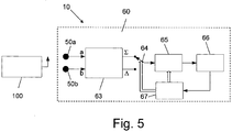
- Fig. 5 illustrates the general structure of the direction finder 10, according to a first hardware embodiment of the invention.
- the direction finder comprises a conventional wireless communication unit 66 that communicates with a similar wireless communication unit (not shown) of the target 100.
- the 180° hybrid junction 63 is used to generate the reference and null patterns 60 and 160 (of Figs. 3 and 4 ) respectively.
- the hybrid junction 63 is connected at its port a to antenna 50a, and at its port b to antenna 50b.
- the reference (i.e., in-phase) pattern 60 is generated at the ⁇ (sum) port and the null (i.e., out-of-phase) pattern 160 is generated at the ⁇ (difference) port.
- Controlled attenuator 65 which is an essential element of the invention, is used for indirect measurement of the relevant antenna pattern value at the direction of the target, using a communication yes/no principle. More specifically, the communication yes/no principle operates as follows: Processing unit 67 accepts from the wireless communication unit 66 the information whether communication with target 100 exists or not. The processing unit controls switch 64, and controlled attenuator according to the following DF procedure. First, in stage 1 the attenuation of attenuator 65 is set to OdB, and a communication between the wireless communication units of the direction finder 66 and the target is established.
- Establishment of communication is regarded as "yes” when data handshake between the two wireless communication units is acquired.
- Loss of communication i.e., "no" communication is regarded when data transfer between the two wireless communication does not exist, for example, due to loss of handshake.
- Attenuation in the wireless communication pass is deliberately introduced by controlled attenuator 65 until communication is lost. More specifically, the attenuation is gradually increased, until loss of communication.
- stage 1 i.e., when the reference pattern is used, the minimal attenuation required to lose communication is recorded, and noted R in dB units.
- the minimal attenuation required to lose communication is recorded also, and noted N in dB units.
- the values of R and N directly depend on the direction to the target, and on the active pattern (i.e., the pattern which is used at that time).
- Fig. 6a shows a situation in which target 100 is positioned off the central axis 21.
- the vector 163 represents the R attenuation required to lose communication in stage 1.
- vector 164 represents the N attenuation required to lose communication in stage 2.
- R becomes maximal, and N becomes minimal.
- N becomes minimal.
- Fig. 6b shows the sector 70 in which (R-N ⁇ 0).
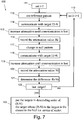
- Fig. 7 is a flow diagram illustrating a procedure 100 for determining the direction when several targets are present (i.e., having wireless communication directly with the DF).
- an index i which represents a number which is assigned to each target ID, is set to 1.
- the reference pattern is activated in step 112, by switching switch 64 ( Fig. 5 ) to the ⁇ position.
- a communication is established with a target #i.
- step 115 the attenuation is increased until loss of communication
- step 116 the attenuation value R corresponding to the point of loss of wireless communication is recorded.
- step 117 switch 64 is turned to the ⁇ position, the attenuation is zeroed, and again communication is established in step 118 with target #i using a null pattern.
- step 119 the attenuation is again increased until loss of communication.
- step 120 the attenuation value N corresponding to the point of loss of wireless communication is recorded.
- step 121 the value of Ri-Ni is determined, and recorded.
- step 122 the procedure checks whether all targets have been treated.
- step 113 the index i is increased by 1 in step 113, and the procedure repeats from step 112 for the new target corresponding to the present I (of step 113). If, however, the answer in step 122 is yes, an analysis of all recorded values of Ri-Ni is performed in step 123. More specifically, in step 123 the targets are arranged in descending order according to their determined Ri-Ni values. Furthermore, it can be concluded that the target with index i whose Ri-Ni value is largest, is the closest to the sector central axis 21.
- the signals at antennas 50a and 50b are not necessarily equal in amplitude and phase when communicating along axis 21.
- cables from the antennas are not necessarily equal, and the 180° hybrid junction 63 is not perfect. This may result in null pattern whose null shifted off the axis 21, and/or the null depth is not maximized.
- the null depth is the difference in dB between the highest and the lowest values in a antenna pattern.
- Fig. 10a shows the general form of the cardioid reference pattern 260a.
- the cardioid reference pattern is generated by an additional 90°-phase shift to the front antenna 250a.
- the cardioid pattern comprises a lobe, which is directed toward central axis 21, and a null directed to the back axis 22.
- Fig. 10b shows the general form of the cardioid null pattern 260b.
- the cardioid null pattern is generated by an additional 90°-phase shift to the back antenna 250b.
- the cardioid pattern comprises a lobe, which is directed toward back axis 22, and a null directed to the front axis 21.
- the procedure as above described with respect to the generation of the vectors R and N is repeated in the cardioid stages 3 and 4.
- stage 3 i.e., when the cardioid reference pattern 260a is generated, the minimal attenuation required to lose communication is recorded, and denoted R c in dB units.
- the cardioid null pattern when the cardioid null pattern is generated, the minimal attenuation required to lose communication is also recorded, and denoted N c in dB units.
- R c and N c directly depend on whether the direction to the target is in the front or the back (i.e., to the direction of axis 21 or axis 22). If R c >N c , it is concluded that the target is in the front of the DF 10. Otherwise, If R c ⁇ N c , it is concluded that the target is in the back of the DF 10.
- Fig. 11 illustrates in a block diagram form the general structure of a directional finder having a front and back discrimination, as described with respect to Figs. 9 , 10a and 10b .
- switch 380 is connected in the position as shown in the figure, thus introducing an additional 90° phase shifter 381 in the path of the front antenna 250a, thereby to generate the cardioid shown in Fig. 10a .
- switch 380 is turned to the lower position shown in the figure, thus introducing the additional 90° phase shifter 381 in the path of the back antenna 250b, thereby to generate the cardioid of Fig. 10b .
- Processing unit 367 in addition to controlling the switch 364 and controlled attenuator 365, controls the switch 380 according to procedure described above.
- the rest of the elements in the figure, i.e., elements 363, 364, 365, 366, 368, and 369 are essentially the same elements 63, 64, 65, 66, 68, and 69 as discussed above.
- Alternate embodiments for acquiring the 90° phase shift are: (a) including a 90° phase shift for stage 3 and 270° phase shift for stage 4 as part of phase shifter 368; and (b) using a quadrature, i.e., 90° hybrid junction instead of the 180° hybrid junction 363.
- reflection of waves is expected from nearby objects, such as walls, or metallic objects.
- waves transmitted from target 100 may be scattered and reflected from nearby object such as wall 93, and arrive the direction finder 10 via many waves two of which 94 and 95 are shown in the figure.
- the reflected waves are much weaker due to the following facts: (a) the reflected waves travel a loner path; (b) The reflected waves are scattered to many directions; and (c) the reflected waves from an object suffer from reflection losses.
- the reflected waves arrive at the DF later than the direct wave due to the longer path.
- a key novel feature of the invention is its ability to overcome multi-path reflections because the direction finding is based on the deliberate loss of communication concept, rather than measuring these signal attributes.
- the existence or non-existence of communication is the basis of the present invention, rather than any specific characteristic of the arrived signal.
- the DF procedure of the present invention is based on the difference R-N rather than absolute values of received signal levels, and therefore the procedure of the present invention is also not affected by the distance between the target and the DF, as long as they can communicate.
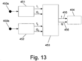
- Fig. 13 generally illustrates in block diagram form the structure of the software based implementation.
- the first antenna 450a is connected to a first RF channel (radio receiver) 451.
- the second antenna 450b is connected to a second RF channel (radio receiver) 452.
- the ADC Analogue to Digital Converter-not shown
- I/Q In-phase/Quadrature
- the first RF channel 451 outputs are denoted I 1 and Q 1 .
- the second RF channel 452 outputs are denoted I 2 and Q 2 .
- Processing unit 453 receives I 1 and I 2 and Q 1 and Q 2 inputs, performs the direction finding technique by calculating new I and Q based on said inputs, and conveys over lines 455 and 456 respectively the newly calculated I and Q to the base-band component 454.
- the deliberate attenuation which is performed in the hardware embodiment by the controlled attenuator 65, is replaced herein by a digital attenuation of the received signals represented by I 1 , Q 1 , and I 2 , Q 2 .
- stage 1 the values of I R and Q R are reduced simultaneously, and in stage 2 the values of I N and Q N are reduced simultaneously.
- stage 3 the values of I Rc and Q Rc are reduced simultaneously, and in stage 4, the values of I Nc and Q Nc are reduced simultaneously.
- the compensation for any amplitude and phase difference which was performed in the hardware implementation by VVA 69 and phase shifter 68, is performed in the software implementation digitally by adding correction factors I', Q', I", and Q", where the correction factors are digital values, that are either positive or negative.
- Q N Q 1 -Q 2 +Q".
- the novelty of the hardware implementation generally resides in all the elements of Figs. 5 , and 8 , excluding the wireless communication unit 66.
- the novelty of the hardware implementation of Fig. 11 generally resides in all the elements shown in the figure, excluding the wireless communication unit 366.
- the novelty of the software implementation of Fig. 13 essentially resides in the processing unit 453.
- the present invention provides a procedure for finding the direction to one or more targets, which is based on yes/no communication.
- the type of communication used between the direction finder and the target is generally irrelevant to the invention, as long as a wireless communication is maintained during a "yes" communications state, and a loss of wireless communication occurs during a "no" communication state.
- the procedure uses an attenuator which intentionally causes loss of communication, wherein the attenuator may attenuate the received signal, the transmitted signal or both.
- the invention determines the difference between the reference pattern and the null pattern in order to find if a target is within a sector of interest.
- the reference pattern may be directional or omni-directional.
- the invention uses at least two antennas, typically omni-directional but also may be directional, for finding the direction.
- a single antenna may be used.
- the deliberately induced attenuation (either by the controlled attenuators 65 or 365 in the hardware embodiments, or digital attenuation in the software embodiments) may be performed gradually, or according to a search algorithm.
- the order by which the reference and null patterns are generated is replaceable.
- the attenuation may start with the highest value where communication does not exist, towards communication existence.
- the target is not required to be equipped with direction finding, but it may include such a feature.
Landscapes
- Physics & Mathematics (AREA)
- Engineering & Computer Science (AREA)
- General Physics & Mathematics (AREA)
- Radar, Positioning & Navigation (AREA)
- Remote Sensing (AREA)
- Radio Transmission System (AREA)
- Position Fixing By Use Of Radio Waves (AREA)
Claims (20)
- Verfahren zum Bestimmen, ob sich ein Zielobjekt (100) innerhalb eines interessierenden Richtungssektors (20) eines Peilers (10) befindet, umfassend:a. Vordefinieren des interessierenden Richtungssektors als eine spezielle Schwellwertdifferenz zwischen einem R-Referenzwert und einem N-Nullwert;b. Vorsehen von mindestens zwei Antennen (50a, 50b), die in einer Breitseitenkonfiguration innerhalb des Peilers angeordnet sind;c. Erzeugen eines phasengleichen Referenzmusters unter Verwendung von mindestens einer der Antennen und Aufbauen einer drahtlosen Kommunikation zwischen dem Peiler und dem Zielobjekt;d. Dämpfen des drahtlosen Kommunikationssignals zwischen dem Peiler und dem Zielobjekt, bis die drahtlose Kommunikation verloren ist, und Aufzeichnen des Dämpfungswertes, der dem Verlust an drahtloser Kommunikation entspricht, als den R-Referenzwert;e. Erzeugen eines phasenverschobenen Nullmusters unter Verwendung von mindestens zwei der Antennen und Wiederaufbauen der drahtlosen Kommunikation zwischen dem Peiler und dem Zielobjekt;f. Dämpfen des drahtlosen Kommunikationssignals zwischen dem Peiler und dem Zielobjekt, bis die drahtlose Kommunikation verloren ist, und Aufzeichnen des Dämpfungswertes, der dem Verlust an drahtloser Kommunikation entspricht, als den N-Nullwert;g. Bestimmen, ob die Differenz R-N oberhalb oder unterhalb der speziellen Schwellwertdifferenz liegt, wobei eine Differenz R-N oberhalb der speziellen Schwellwertdifferenz anzeigt, dass sich das Zielobjekt innerhalb des interessierenden Richtungssektors befindet, und wobei eine Differenz R-N unterhalb der speziellen Schwellwertdifferenz anzeigt, dass sich das Zielobjekt außerhalb des interessierenden Richtungssektors befindet.
- Verfahren nach Anspruch 1, wobei ein Verlust an drahtloser Kommunikation ein Verlust an "Handshake" (Übergabe) zwischen dem Peiler und dem Zielobjekt ist.
- Verfahren nach Anspruch 1, wobei eine größere Differenz R-N anzeigt, dass sich die Richtung zu dem Zielobjekt näher an einer Mittelachse des interessierenden Richtungssektors befindet.
- Verfahren nach Anspruch 1, wobei der interessierende Richtungssektor umso kleiner wird, je kleiner die vordefinierte spezielle Schwellwertdifferenz ist, und umgekehrt der interessierende Richtungssektor umso breiter wird, je größer die vordefinierte spezielle Schwellwertdifferenz ist.
- Verfahren nach Anspruch 1, wobei die Reihenfolge der Erzeugung der Referenz- und Nullmuster, die entsprechenden Dämpfungen und Aufzeichnungen einschließend, austauschbar ist.
- Verfahren nach Anspruch 1, wobei das drahtlose Kommunikationssignal, das gedämpft ist, das bei dem Peiler empfangene Signal ist.
- Verfahren nach Anspruch 1, wobei das drahtlose Kommunikationssignal, das gedämpft ist, das von dem Peiler abgestrahlte Signal ist.
- Verfahren nach Anspruch 1, wobei die Dämpfungen schrittweise durchgeführt werden.
- Verfahren nach Anspruch 1, wobei die Dämpfungen gemäß einem spezifisch ausgewählten Verfahren bis zum Verlust der drahtlosen Kommunikation durchgeführt werden.
- Verfahren nach Anspruch 1, wobei die Dämpfungen mit einer Dämpfung von 0dB beginnen und die Dämpfungswerte in dB gemessen werden.
- Verfahren nach Anspruch 1, wobei die Reihenfolge der Bestimmung von N bzw. R austauschbar ist.
- Verfahren nach Anspruch 1, ferner mit einem Vorsehen einer Unterscheidung zwischen Vorne und Hinten, ferner umfassend:a. Vorsehen von mindestens zwei Antennen (250a, 250b), die in einer Heckabstrahlkonfiguration innerhalb des Peilers angeordnet sind;b. Erzeugen eines Quadraturphasen-Nierenreferenzmusters unter Verwendung von mindestens zwei der Antennen, die in einer Heckabstrahlkonfiguration angeordnet sind, und Aufbauen einer drahtlosen Kommunikation zwischen dem Peiler und dem Zielobjekt;c. Dämpfen des drahtlosen Kommunikationssignals zwischen dem Peiler und dem Zielobjekt, bis die drahtlose Kommunikation verloren ist, und Aufzeichnen des Dämpfungswertes, der dem Verlust an drahtloser Kommunikation entspricht, als den Rc-Referenzwert ;d. Erzeugen eines weiteren Quadraturphasen-Nierennullmusters unter Verwendung von mindestens zwei der Antennen, die in einer Heckabstrahlkonfiguration angeordnet sind, und Wiederaufbauen der drahtlosen Kommunikation zwischen dem Peiler und dem Zielobjekt;e. Dämpfen des drahtlosen Kommunikationssignals zwischen dem Peiler und dem Zielobjekt, bis die drahtlose Kommunikation verloren ist, und Aufzeichnen des Dämpfungswertes, der dem Verlust an drahtloser Kommunikation entspricht, als den Nc-Nullwert;f. Bestimmen, ob die Differenz Rc-Nc positiv oder negativ ist, wobei ein positives Rc-Nc anzeigt, dass sich das Zielobjekt vor dem Peiler befindet, und wobei ein negatives Rc-Nc anzeigt, dass sich das Zielobjekt hinter dem Peiler befindet.
- Verfahren nach Anspruch 12, wobei die Referenz- und Null-Nierenmuster während des Einführens einer 90° Phasenverschiebung an der Vorderseite bzw. der Rückseite der Heckabstrahlantennen erzeugt werden.
- Verfahren nach Anspruch 1, wobei die Erzeugung des phasengleichen Referenzmusters und des phasenverschobenen Nullmusters sowie der entsprechenden Dämpfungen der Signale digital durch eine Verarbeitungseinheit durchgeführt werden.
- Verfahren nach Anspruch 12, wobei die Erzeugung des Quadraturphasen-Nierenreferenzmusters und des weiteren Quadraturphasen-Nierennullmusters sowie die entsprechenden Dämpfungen der Signale digital durch eine Verarbeitungseinheit durchgeführt werden.
- Verfahren nach Anspruch 14 oder 15, wobei die Prozessoreinheit I1 und Q1 von einem ersten Empfänger, der seinerseits das Signal über eine erste der beiden Antennen empfängt, und I2 und Q2 von einem zweiten Empfänger empfängt, der seinerseits das Signal von einer zweiten der beiden Antennen empfängt, und wobei die Prozessoreinheit ein neu berechnetes entsprechendes I und Q an eine Basisbandkomponente ausgibt.
- Peiler (10) zum Bestimmen, ob sich ein Zielobjekt (100) innerhalb eines vordefinierten interessierenden Richtungssektors (20) befindet, der als eine spezielle Schwellwertdifferenz zwischen einem R-Referenzwert und einem N-Nullwert vordefiniert ist, wobei der Peiler aufweist:a. mindestens zwei Antennen (50a, 50b), die in einer Breitseitenkonfiguration angeordnet sind;b. eine drahtlose Kommunikationseinheit (66) zum Aufbauen einer Kommunikation mit einem Zielobjekt über ein drahtloses Kommunikationssignal;c. ein variables Dämpfungsglied (65) zum Dämpfen des drahtlosen Kommunikationssignals;d. eine Hybridverbindung (63) zur Ermöglichung einer drahtlosen Kommunikation des Signals über die Antennen in einem erzeugten phasengleichen oder phasenverschobenen Muster; unde. eine Verarbeitungseinheit (67), die für Folgendes ausgelegt ist:e.1. Schalten der Hybridverbindung bei einer Stufe 1, um ein phasengleiches Muster zu erzeugen, Dämpfen des Signals, bis die drahtlose Kommunikation verloren ist, und Aufzeichnen des Dämpfungswertes, der dem Verlust an drahtloser Kommunikation entspricht, als einen R-Referenzwert;e.2. Schalten der Hybridverbindung bei einer Stufe 2, um ein phasenverschobenes Muster zu erzeugen, Dämpfen des Signals, bis die drahtlose Kommunikation verloren ist, und Aufzeichnen des Dämpfungswertes, der dem Verlust an drahtloser Kommunikation entspricht, als einen N-Nullwert;e.3. Bestimmen der Differenz R-N, wobei eine Differenz oberhalb der vordefinierten speziellen Schwellwertdifferenz bedeutet, dass sich das Zielobjekt innerhalb des interessierenden Richtungssektors befindet, und eine Differenz unterhalb der vordefinierten speziellen Schwellwertdifferenz bedeutet, dass sich das Zielobjekt außerhalb des interessierenden Richtungssektors befindet.
- Peiler nach Anspruch 17, der zusätzlich zwischen Zielobjekten unterscheidet, die sich vor oder hinter dem Peiler befinden, ferner aufweisend:f. einen Phasenschieber (381);g. mindestens zwei Antennen (250a, 250b), die in einer Heckabstrahlkonfiguration angeordnet sind;h. und wobei die Prozessoreinheit (67) außerdem für Folgendes ausgelegt ist:h.1. Schalten des Phasenschiebers bei einer Stufe 3, um ein Quadraturphasen-Nierenreferenzmuster an den zwei Antennen zu erzeugen, die in einer Heckabstrahlkonfiguration angeordnet sind, Dämpfen des Signals, bis die drahtlose Kommunikation verloren ist, und Aufzeichnen des Dämpfungswertes, der dem Verlust an drahtloser Kommunikation entspricht, als einen Rc-Nierenreferenzwert;h.2. Schalten des Phasenschiebers bei einer Stufe 4, um ein weiteres Quadraturphasen-Nierennullmuster an den zwei Antennen zu erzeugen, die in einer Heckabstrahlkonfiguration angeordnet sind, Dämpfen des Signals, bis die drahtlose Kommunikation verloren ist, und Aufzeichnen des Dämpfungswertes, der dem Verlust an drahtloser Kommunikation entspricht, als einen Nc-Nierennullwert;h.3. Ermitteln der Differenz Rc-Nc, wobei eine positive Differenz anzeigt, dass sich das Zielobjekt vor dem Peiler befindet, und wobei eine negative Differenz anzeigt, dass sich das Zielobjekt hinter dem Peiler befindet.
- Peiler nach Anspruch 17, wobei die Hybridverbindung eine 180° Hybridverbindung ist.
- Peiler nach Anspruch 18, wobei der Phasenschieber ein 90° Phasenschieber ist.
Applications Claiming Priority (3)
| Application Number | Priority Date | Filing Date | Title |
|---|---|---|---|
| US5822308P | 2008-06-03 | 2008-06-03 | |
| US16304709P | 2009-03-25 | 2009-03-25 | |
| PCT/IL2009/000542 WO2009147662A1 (en) | 2008-06-03 | 2009-06-01 | Direction finding method and device |
Publications (2)
| Publication Number | Publication Date |
|---|---|
| EP2294440A1 EP2294440A1 (de) | 2011-03-16 |
| EP2294440B1 true EP2294440B1 (de) | 2019-02-20 |
Family
ID=41170989
Family Applications (1)
| Application Number | Title | Priority Date | Filing Date |
|---|---|---|---|
| EP09758006.2A Not-in-force EP2294440B1 (de) | 2008-06-03 | 2009-06-01 | Richtungsfindungsverfahren und -vorrichtung |
Country Status (4)
| Country | Link |
|---|---|
| US (1) | US8405549B2 (de) |
| EP (1) | EP2294440B1 (de) |
| CN (1) | CN102016623A (de) |
| WO (1) | WO2009147662A1 (de) |
Cited By (1)
| Publication number | Priority date | Publication date | Assignee | Title |
|---|---|---|---|---|
| US11398685B2 (en) | 2019-10-18 | 2022-07-26 | Rohde & Schwarz Gmbh & Co. Kg | Antenna system and antenna controlling method |
Families Citing this family (16)
| Publication number | Priority date | Publication date | Assignee | Title |
|---|---|---|---|---|
| US8797213B2 (en) * | 2009-09-30 | 2014-08-05 | Broadcom Corporation | Methods and systems for estimating angle of arrival |
| KR100971773B1 (ko) * | 2009-11-13 | 2010-07-21 | 엘아이지넥스원 주식회사 | 전자 정보 수신기의 신호 식별 방법 |
| DE202010016472U1 (de) | 2009-12-15 | 2011-03-24 | Isensee, Gerrit Ragnar Ulrich Friedrich, Maspalomas | Modul zur Simulation einer belegten Sitzkontaktmatte in Fahrzeugen |
| US8988283B2 (en) | 2010-03-17 | 2015-03-24 | Hisep Technology Ltd. | Direction finding system device and method |
| US9215535B2 (en) | 2010-11-24 | 2015-12-15 | Sonova Ag | Hearing assistance system and method |
| US9151819B2 (en) * | 2011-07-08 | 2015-10-06 | Psion Inc. | Antenna apparatus for determining the position of a radio-frequency transponder |
| US10591575B2 (en) | 2015-04-22 | 2020-03-17 | Hisep Technology Ltd. | Direction finding system device and method |
| US10422851B2 (en) * | 2015-12-02 | 2019-09-24 | Hisep Technology Ltd. | Directional awareness for wireless sensor nodes |
| DE102016213240A1 (de) * | 2016-02-12 | 2017-08-17 | Fraunhofer-Gesellschaft zur Förderung der angewandten Forschung e.V. | Vorrichtung und Verfahren zur Positionsbestimmung eines Senders relativ zu einem Detektionsbereich |
| DE102016213229A1 (de) | 2016-02-12 | 2017-08-17 | Fraunhofer-Gesellschaft zur Förderung der angewandten Forschung e.V. | Vorrichtung und Verfahren zur Bestimmung einer Position eines Senders |
| RU2634299C1 (ru) * | 2016-12-08 | 2017-10-26 | Федеральное государственное бюджетное образовательное учреждение высшего образования "Московский технологический университет" | Фазовый радиопеленгатор |
| US10568132B2 (en) | 2017-01-13 | 2020-02-18 | Sony Corporation | Contention-based random access with receive beamforming in wireless networks |
| US11039370B2 (en) | 2017-07-19 | 2021-06-15 | Hewlett-Packard Development Company, L.P. | Automatic routing based on dual-capability Wi-Fi systems |
| FR3078599B1 (fr) * | 2018-03-01 | 2021-03-05 | Airbus Helicopters | Systeme de geolocalisation, aeronef et procede de geolocalisation associe |
| US12298426B2 (en) * | 2021-04-28 | 2025-05-13 | Raytheon Company | Low swap aperture for direction finding across extreme wide band |
| JP7632958B2 (ja) * | 2021-09-01 | 2025-02-19 | パナソニックオートモーティブシステムズ株式会社 | 測定装置、測定方法、及び測定プログラム |
Family Cites Families (4)
| Publication number | Priority date | Publication date | Assignee | Title |
|---|---|---|---|---|
| US5402132A (en) * | 1992-05-29 | 1995-03-28 | Mcdonnell Douglas Corporation | Monopole/crossed slot single antenna direction finding system |
| US5617102A (en) * | 1994-11-18 | 1997-04-01 | At&T Global Information Solutions Company | Communications transceiver using an adaptive directional antenna |
| US7577464B2 (en) * | 2004-06-18 | 2009-08-18 | Toyon Research Corporation | Compact antenna system for polarization sensitive null steering and direction-finding |
| JP4123195B2 (ja) | 2004-06-22 | 2008-07-23 | オムロン株式会社 | タグ通信装置、タグ通信装置の制御方法、タグ通信制御プログラム、および、タグ通信管理システム |
-
2009
- 2009-06-01 US US12/993,118 patent/US8405549B2/en active Active
- 2009-06-01 WO PCT/IL2009/000542 patent/WO2009147662A1/en not_active Ceased
- 2009-06-01 CN CN2009801205754A patent/CN102016623A/zh active Pending
- 2009-06-01 EP EP09758006.2A patent/EP2294440B1/de not_active Not-in-force
Non-Patent Citations (1)
| Title |
|---|
| None * |
Cited By (1)
| Publication number | Priority date | Publication date | Assignee | Title |
|---|---|---|---|---|
| US11398685B2 (en) | 2019-10-18 | 2022-07-26 | Rohde & Schwarz Gmbh & Co. Kg | Antenna system and antenna controlling method |
Also Published As
| Publication number | Publication date |
|---|---|
| US20110068980A1 (en) | 2011-03-24 |
| US8405549B2 (en) | 2013-03-26 |
| CN102016623A (zh) | 2011-04-13 |
| WO2009147662A1 (en) | 2009-12-10 |
| EP2294440A1 (de) | 2011-03-16 |
Similar Documents
| Publication | Publication Date | Title |
|---|---|---|
| US8405549B2 (en) | Direction finding method and device | |
| JP6910557B2 (ja) | 第2のデバイスの既知のロケーションに基づいて第1のデバイスのロケーションを求めるミリ波通信システム及び方法 | |
| US8223073B2 (en) | Apparatus and method for a directional finder | |
| EP2789181B1 (de) | Verfahren, vorrichtung und computerprogrammprodukt für eine auf einer richtungsmessung basierende abgrenzung in sicherer distanz | |
| US5739788A (en) | Adaptive receiving antenna for beam repositioning | |
| US10591575B2 (en) | Direction finding system device and method | |
| US20130265196A1 (en) | Methods and systems useful in connection with multipath | |
| KR20200125524A (ko) | 위치 측정 장치 | |
| EP3120417B1 (de) | Verfahren zum finden der signalrichtung mit einer modalen antenne | |
| US11841451B2 (en) | Communication device and method | |
| GB2367455A (en) | Interference reduction in a cellular communication system having a beamed downlink | |
| US12155440B2 (en) | Communication device, control device, storage medium, and system for estimating a positional relation between devices | |
| EP1780909A1 (de) | Basisstation und mobileinheit eines mobilkommunikationssystems und azimut-bestimmungsverfahren | |
| CN119738806A (zh) | 具有基于自干扰的补偿的雷达装置 | |
| He | A novel wireless sensor networks multilateration positioning method based on quartic double-well bistable stochastic resonance technique | |
| CN105589063A (zh) | 基于偏度的脉冲无线电60GHz测距方法 | |
| Sharma et al. | A multi-cell UWB-IR localization system for robot navigation | |
| KR20200107387A (ko) | 위치 측정 장치 | |
| WO2024199623A1 (en) | Devices and methods for localization of a wi-fi station | |
| Subramanian et al. | A scalable uwb based scheme for localization in wireless networks | |
| KR20170073530A (ko) | 단말 이동시 빔 트래킹 방법 및 이를 포함하는 단말 | |
| Kitamura et al. | RSSI-ranging method using pattern diversity and distance-based reliability function. | |
| JP2004297664A (ja) | 移動局、通信制御方法 | |
| JP2013020408A (ja) | 侵入検知システム、侵入検知装置、侵入検知方法および侵入検知プログラム |
Legal Events
| Date | Code | Title | Description |
|---|---|---|---|
| PUAI | Public reference made under article 153(3) epc to a published international application that has entered the european phase |
Free format text: ORIGINAL CODE: 0009012 |
|
| 17P | Request for examination filed |
Effective date: 20101118 |
|
| AK | Designated contracting states |
Kind code of ref document: A1 Designated state(s): AT BE BG CH CY CZ DE DK EE ES FI FR GB GR HR HU IE IS IT LI LT LU LV MC MK MT NL NO PL PT RO SE SI SK TR |
|
| AX | Request for extension of the european patent |
Extension state: AL BA RS |
|
| DAX | Request for extension of the european patent (deleted) | ||
| GRAP | Despatch of communication of intention to grant a patent |
Free format text: ORIGINAL CODE: EPIDOSNIGR1 |
|
| STAA | Information on the status of an ep patent application or granted ep patent |
Free format text: STATUS: GRANT OF PATENT IS INTENDED |
|
| INTG | Intention to grant announced |
Effective date: 20180831 |
|
| GRAS | Grant fee paid |
Free format text: ORIGINAL CODE: EPIDOSNIGR3 |
|
| GRAA | (expected) grant |
Free format text: ORIGINAL CODE: 0009210 |
|
| STAA | Information on the status of an ep patent application or granted ep patent |
Free format text: STATUS: THE PATENT HAS BEEN GRANTED |
|
| AK | Designated contracting states |
Kind code of ref document: B1 Designated state(s): AT BE BG CH CY CZ DE DK EE ES FI FR GB GR HR HU IE IS IT LI LT LU LV MC MK MT NL NO PL PT RO SE SI SK TR |
|
| REG | Reference to a national code |
Ref country code: GB Ref legal event code: FG4D |
|
| REG | Reference to a national code |
Ref country code: CH Ref legal event code: EP |
|
| REG | Reference to a national code |
Ref country code: DE Ref legal event code: R096 Ref document number: 602009057061 Country of ref document: DE |
|
| REG | Reference to a national code |
Ref country code: AT Ref legal event code: REF Ref document number: 1098921 Country of ref document: AT Kind code of ref document: T Effective date: 20190315 |
|
| REG | Reference to a national code |
Ref country code: IE Ref legal event code: FG4D |
|
| REG | Reference to a national code |
Ref country code: LT Ref legal event code: MG4D |
|
| REG | Reference to a national code |
Ref country code: NL Ref legal event code: MP Effective date: 20190220 |
|
| PG25 | Lapsed in a contracting state [announced via postgrant information from national office to epo] |
Ref country code: NO Free format text: LAPSE BECAUSE OF FAILURE TO SUBMIT A TRANSLATION OF THE DESCRIPTION OR TO PAY THE FEE WITHIN THE PRESCRIBED TIME-LIMIT Effective date: 20190520 Ref country code: PT Free format text: LAPSE BECAUSE OF FAILURE TO SUBMIT A TRANSLATION OF THE DESCRIPTION OR TO PAY THE FEE WITHIN THE PRESCRIBED TIME-LIMIT Effective date: 20190620 Ref country code: FI Free format text: LAPSE BECAUSE OF FAILURE TO SUBMIT A TRANSLATION OF THE DESCRIPTION OR TO PAY THE FEE WITHIN THE PRESCRIBED TIME-LIMIT Effective date: 20190220 Ref country code: SE Free format text: LAPSE BECAUSE OF FAILURE TO SUBMIT A TRANSLATION OF THE DESCRIPTION OR TO PAY THE FEE WITHIN THE PRESCRIBED TIME-LIMIT Effective date: 20190220 Ref country code: LT Free format text: LAPSE BECAUSE OF FAILURE TO SUBMIT A TRANSLATION OF THE DESCRIPTION OR TO PAY THE FEE WITHIN THE PRESCRIBED TIME-LIMIT Effective date: 20190220 |
|
| PG25 | Lapsed in a contracting state [announced via postgrant information from national office to epo] |
Ref country code: HR Free format text: LAPSE BECAUSE OF FAILURE TO SUBMIT A TRANSLATION OF THE DESCRIPTION OR TO PAY THE FEE WITHIN THE PRESCRIBED TIME-LIMIT Effective date: 20190220 Ref country code: NL Free format text: LAPSE BECAUSE OF FAILURE TO SUBMIT A TRANSLATION OF THE DESCRIPTION OR TO PAY THE FEE WITHIN THE PRESCRIBED TIME-LIMIT Effective date: 20190220 Ref country code: BG Free format text: LAPSE BECAUSE OF FAILURE TO SUBMIT A TRANSLATION OF THE DESCRIPTION OR TO PAY THE FEE WITHIN THE PRESCRIBED TIME-LIMIT Effective date: 20190520 Ref country code: GR Free format text: LAPSE BECAUSE OF FAILURE TO SUBMIT A TRANSLATION OF THE DESCRIPTION OR TO PAY THE FEE WITHIN THE PRESCRIBED TIME-LIMIT Effective date: 20190521 Ref country code: LV Free format text: LAPSE BECAUSE OF FAILURE TO SUBMIT A TRANSLATION OF THE DESCRIPTION OR TO PAY THE FEE WITHIN THE PRESCRIBED TIME-LIMIT Effective date: 20190220 Ref country code: IS Free format text: LAPSE BECAUSE OF FAILURE TO SUBMIT A TRANSLATION OF THE DESCRIPTION OR TO PAY THE FEE WITHIN THE PRESCRIBED TIME-LIMIT Effective date: 20190620 |
|
| REG | Reference to a national code |
Ref country code: AT Ref legal event code: MK05 Ref document number: 1098921 Country of ref document: AT Kind code of ref document: T Effective date: 20190220 |
|
| PG25 | Lapsed in a contracting state [announced via postgrant information from national office to epo] |
Ref country code: EE Free format text: LAPSE BECAUSE OF FAILURE TO SUBMIT A TRANSLATION OF THE DESCRIPTION OR TO PAY THE FEE WITHIN THE PRESCRIBED TIME-LIMIT Effective date: 20190220 Ref country code: SK Free format text: LAPSE BECAUSE OF FAILURE TO SUBMIT A TRANSLATION OF THE DESCRIPTION OR TO PAY THE FEE WITHIN THE PRESCRIBED TIME-LIMIT Effective date: 20190220 Ref country code: IT Free format text: LAPSE BECAUSE OF FAILURE TO SUBMIT A TRANSLATION OF THE DESCRIPTION OR TO PAY THE FEE WITHIN THE PRESCRIBED TIME-LIMIT Effective date: 20190220 Ref country code: DK Free format text: LAPSE BECAUSE OF FAILURE TO SUBMIT A TRANSLATION OF THE DESCRIPTION OR TO PAY THE FEE WITHIN THE PRESCRIBED TIME-LIMIT Effective date: 20190220 Ref country code: RO Free format text: LAPSE BECAUSE OF FAILURE TO SUBMIT A TRANSLATION OF THE DESCRIPTION OR TO PAY THE FEE WITHIN THE PRESCRIBED TIME-LIMIT Effective date: 20190220 Ref country code: CZ Free format text: LAPSE BECAUSE OF FAILURE TO SUBMIT A TRANSLATION OF THE DESCRIPTION OR TO PAY THE FEE WITHIN THE PRESCRIBED TIME-LIMIT Effective date: 20190220 Ref country code: ES Free format text: LAPSE BECAUSE OF FAILURE TO SUBMIT A TRANSLATION OF THE DESCRIPTION OR TO PAY THE FEE WITHIN THE PRESCRIBED TIME-LIMIT Effective date: 20190220 |
|
| REG | Reference to a national code |
Ref country code: DE Ref legal event code: R097 Ref document number: 602009057061 Country of ref document: DE |
|
| PG25 | Lapsed in a contracting state [announced via postgrant information from national office to epo] |
Ref country code: PL Free format text: LAPSE BECAUSE OF FAILURE TO SUBMIT A TRANSLATION OF THE DESCRIPTION OR TO PAY THE FEE WITHIN THE PRESCRIBED TIME-LIMIT Effective date: 20190220 |
|
| PLBE | No opposition filed within time limit |
Free format text: ORIGINAL CODE: 0009261 |
|
| STAA | Information on the status of an ep patent application or granted ep patent |
Free format text: STATUS: NO OPPOSITION FILED WITHIN TIME LIMIT |
|
| PG25 | Lapsed in a contracting state [announced via postgrant information from national office to epo] |
Ref country code: AT Free format text: LAPSE BECAUSE OF FAILURE TO SUBMIT A TRANSLATION OF THE DESCRIPTION OR TO PAY THE FEE WITHIN THE PRESCRIBED TIME-LIMIT Effective date: 20190220 |
|
| 26N | No opposition filed |
Effective date: 20191121 |
|
| PG25 | Lapsed in a contracting state [announced via postgrant information from national office to epo] |
Ref country code: MC Free format text: LAPSE BECAUSE OF FAILURE TO SUBMIT A TRANSLATION OF THE DESCRIPTION OR TO PAY THE FEE WITHIN THE PRESCRIBED TIME-LIMIT Effective date: 20190220 |
|
| REG | Reference to a national code |
Ref country code: CH Ref legal event code: PL |
|
| GBPC | Gb: european patent ceased through non-payment of renewal fee |
Effective date: 20190601 |
|
| PG25 | Lapsed in a contracting state [announced via postgrant information from national office to epo] |
Ref country code: SI Free format text: LAPSE BECAUSE OF FAILURE TO SUBMIT A TRANSLATION OF THE DESCRIPTION OR TO PAY THE FEE WITHIN THE PRESCRIBED TIME-LIMIT Effective date: 20190220 |
|
| REG | Reference to a national code |
Ref country code: BE Ref legal event code: MM Effective date: 20190630 |
|
| PG25 | Lapsed in a contracting state [announced via postgrant information from national office to epo] |
Ref country code: TR Free format text: LAPSE BECAUSE OF FAILURE TO SUBMIT A TRANSLATION OF THE DESCRIPTION OR TO PAY THE FEE WITHIN THE PRESCRIBED TIME-LIMIT Effective date: 20190220 |
|
| PG25 | Lapsed in a contracting state [announced via postgrant information from national office to epo] |
Ref country code: GB Free format text: LAPSE BECAUSE OF NON-PAYMENT OF DUE FEES Effective date: 20190601 Ref country code: IE Free format text: LAPSE BECAUSE OF NON-PAYMENT OF DUE FEES Effective date: 20190601 |
|
| PG25 | Lapsed in a contracting state [announced via postgrant information from national office to epo] |
Ref country code: LU Free format text: LAPSE BECAUSE OF NON-PAYMENT OF DUE FEES Effective date: 20190601 Ref country code: BE Free format text: LAPSE BECAUSE OF NON-PAYMENT OF DUE FEES Effective date: 20190630 Ref country code: CH Free format text: LAPSE BECAUSE OF NON-PAYMENT OF DUE FEES Effective date: 20190630 Ref country code: LI Free format text: LAPSE BECAUSE OF NON-PAYMENT OF DUE FEES Effective date: 20190630 |
|
| PG25 | Lapsed in a contracting state [announced via postgrant information from national office to epo] |
Ref country code: FR Free format text: LAPSE BECAUSE OF NON-PAYMENT OF DUE FEES Effective date: 20190630 |
|
| PG25 | Lapsed in a contracting state [announced via postgrant information from national office to epo] |
Ref country code: CY Free format text: LAPSE BECAUSE OF FAILURE TO SUBMIT A TRANSLATION OF THE DESCRIPTION OR TO PAY THE FEE WITHIN THE PRESCRIBED TIME-LIMIT Effective date: 20190220 |
|
| PG25 | Lapsed in a contracting state [announced via postgrant information from national office to epo] |
Ref country code: HU Free format text: LAPSE BECAUSE OF FAILURE TO SUBMIT A TRANSLATION OF THE DESCRIPTION OR TO PAY THE FEE WITHIN THE PRESCRIBED TIME-LIMIT; INVALID AB INITIO Effective date: 20090601 Ref country code: MT Free format text: LAPSE BECAUSE OF FAILURE TO SUBMIT A TRANSLATION OF THE DESCRIPTION OR TO PAY THE FEE WITHIN THE PRESCRIBED TIME-LIMIT Effective date: 20190220 |
|
| PG25 | Lapsed in a contracting state [announced via postgrant information from national office to epo] |
Ref country code: MK Free format text: LAPSE BECAUSE OF FAILURE TO SUBMIT A TRANSLATION OF THE DESCRIPTION OR TO PAY THE FEE WITHIN THE PRESCRIBED TIME-LIMIT Effective date: 20190220 |
|
| PGFP | Annual fee paid to national office [announced via postgrant information from national office to epo] |
Ref country code: DE Payment date: 20220630 Year of fee payment: 14 |
|
| REG | Reference to a national code |
Ref country code: DE Ref legal event code: R119 Ref document number: 602009057061 Country of ref document: DE |
|
| PG25 | Lapsed in a contracting state [announced via postgrant information from national office to epo] |
Ref country code: DE Free format text: LAPSE BECAUSE OF NON-PAYMENT OF DUE FEES Effective date: 20240103 |