EP2294483B1 - Projektionssystem - Google Patents
Projektionssystem Download PDFInfo
- Publication number
- EP2294483B1 EP2294483B1 EP09768979A EP09768979A EP2294483B1 EP 2294483 B1 EP2294483 B1 EP 2294483B1 EP 09768979 A EP09768979 A EP 09768979A EP 09768979 A EP09768979 A EP 09768979A EP 2294483 B1 EP2294483 B1 EP 2294483B1
- Authority
- EP
- European Patent Office
- Prior art keywords
- tilting
- tilting mirror
- modulator
- projection system
- lens
- Prior art date
- Legal status (The legal status is an assumption and is not a legal conclusion. Google has not performed a legal analysis and makes no representation as to the accuracy of the status listed.)
- Active
Links
Images



Classifications
-
- G—PHYSICS
- G03—PHOTOGRAPHY; CINEMATOGRAPHY; ANALOGOUS TECHNIQUES USING WAVES OTHER THAN OPTICAL WAVES; ELECTROGRAPHY; HOLOGRAPHY
- G03B—APPARATUS OR ARRANGEMENTS FOR TAKING PHOTOGRAPHS OR FOR PROJECTING OR VIEWING THEM; APPARATUS OR ARRANGEMENTS EMPLOYING ANALOGOUS TECHNIQUES USING WAVES OTHER THAN OPTICAL WAVES; ACCESSORIES THEREFOR
- G03B21/00—Projectors or projection-type viewers; Accessories therefor
- G03B21/14—Details
- G03B21/28—Reflectors in projection beam
-
- H—ELECTRICITY
- H04—ELECTRIC COMMUNICATION TECHNIQUE
- H04N—PICTORIAL COMMUNICATION, e.g. TELEVISION
- H04N9/00—Details of colour television systems
- H04N9/12—Picture reproducers
- H04N9/31—Projection devices for colour picture display, e.g. using electronic spatial light modulators [ESLM]
- H04N9/3102—Projection devices for colour picture display, e.g. using electronic spatial light modulators [ESLM] using two-dimensional electronic spatial light modulators
- H04N9/312—Driving therefor
- H04N9/3126—Driving therefor for spatial light modulators in series
-
- G—PHYSICS
- G03—PHOTOGRAPHY; CINEMATOGRAPHY; ANALOGOUS TECHNIQUES USING WAVES OTHER THAN OPTICAL WAVES; ELECTROGRAPHY; HOLOGRAPHY
- G03B—APPARATUS OR ARRANGEMENTS FOR TAKING PHOTOGRAPHS OR FOR PROJECTING OR VIEWING THEM; APPARATUS OR ARRANGEMENTS EMPLOYING ANALOGOUS TECHNIQUES USING WAVES OTHER THAN OPTICAL WAVES; ACCESSORIES THEREFOR
- G03B21/00—Projectors or projection-type viewers; Accessories therefor
- G03B21/005—Projectors using an electronic spatial light modulator but not peculiar thereto
- G03B21/008—Projectors using an electronic spatial light modulator but not peculiar thereto using micromirror devices
Definitions
- the present invention relates to a projection system according to the preamble of claim 1.
- a projection system is known for example from EP 1 269 756 and the US 2003 / 0026335A1 known.
- the EP 1 549 056 A2 , the FR 2 899 980A1 , the WO 2004/102973 A1 and the US 2006/055897 A1 each show a projection system in which an imaging optics a first light modulator on a second light modulator imaged.
- the tilted arrangement of the aperture diaphragm, the imaging optics can be designed so that the aberrations can be minimized.
- beam path convolutions are understood as all beam path convolutions which have no imaging property. So this is about optical path folds on flat surfaces. These serve to increase the compactness of the device, but have no influence on the imaging quality of the imaging optics, so that the tilt of the aperture diaphragm is related to the modulator without any ray path folds.
- the tilting mirrors of the two tilting mirror matrices can be switched or brought into a first and a second tilted position.
- the imaging optics By forming the imaging optics e.g. according to claim 1 or 3, it is possible to minimize the aberrations of the imaging optics while reducing the number of elements of the imaging optics.
- the imaging optics may have only the plano-convex lens and the rear-side mirrored lens.
- the rear-side mirrored lens preferably has only spherical interfaces.
- the angle predetermined by the tilted positions are optimally utilized.
- the imaging optics are easier to adjust. It is also easier to adjust a projection optics arranged downstream of the second tilting mirror matrix since the light reflected by the tilting mirrors located in the first tilting position runs perpendicular to the modulator surface of the second tilting mirror matrix.
- the imaging optics can be designed in particular as a 1: 1 imaging optics. However, it can also be designed as magnifying or reducing imaging optics.
- the projection systems according to the invention can in particular be designed in each case as a projector for applications in a planetarium in such a way that the image to be projected is projected onto a curved projection surface.
- the curved projection surface can be part of a planetarium dome.
- the projection is usually done in the dark, so that the black level reduction achieved brings a significant image improvement with it.
- the projection systems can furthermore each be designed as a projector for the front projection or as a projector for the rear projection.
- the projection surface can be part of the projector.
- the imaging optics and / or the deflection optics can use a single material for the material passing through the light.
- the lenses of the imaging optics and the deflecting prisms of the deflection optics can be made of the same material.
- the projection systems may have further, known in the art parts or modules, so that the desired image can be projected.
- the two modulators 3, 5 are each formed as Kippaptrix having n x m tilting mirrors in columns and rows, the tilting mirror can be brought independently of each other in a first and in a second tilted position.
- the imaging optics 4 is formed as a 1: 1 imaging optics with a first plano-convex lens 8 and a second rear-mirrored lens 9 and maps each tilting mirror of the illumination modulator 3 exactly on a tilting mirror of the image modulator 5, so that each tilting mirror (hereinafter also called illumination pixels ) of the illumination modulator 3 is associated with exactly one tilting mirror (also referred to below as an image pixel) of the image modulator 5.
- illumination pixels also called illumination pixels
- an image pixel also referred to below as an image pixel
- Other assignments of picture and illumination pixels are also possible. So z. B. an offset in the row direction can be effected so that each image pixel is illuminated by two illumination pixels (each half).
- the two modulators 3 and 5 are controlled by the control unit 7 based on supplied image data BD so that the illumination modulator 3, which is acted upon by the light (eg white light) of the light source 2, a flat modulated light source for the image modulator 5, with the image to be projected is generated or modulated, which is then projected onto a projection surface 10 by means of the projection optics 6.
- the illumination modulator 3 which is acted upon by the light (eg white light) of the light source 2
- a flat modulated light source for the image modulator 5 with the image to be projected is generated or modulated, which is then projected onto a projection surface 10 by means of the projection optics 6.
- the illumination modulator can be controlled such that only the light reflected from the tilting mirrors of the illumination modulator and associated with a tilting mirror of the image modulator which is intended to produce a non-black pixel in the image is imaged onto the image modulator 5. It can thereby be achieved that image pixels of the image modulator, which are intended to represent black pixels, are not exposed to light (since the associated illumination pixels or the light reflected by them do not impinge on the light source) Image modulator is displayed). This advantageously results in that the black level (ie the unwanted residual brightness of a black pixel in the actual projected image) can be significantly reduced.
- Fig. 2 is representative of each tilting mirror matrix 3, 5 respectively only a single tilting mirror K3, K5 shown in its two possible tilted positions.
- the tilting mirrors K3 and K5 are shown in a sectional view, which is selected such that the respective tilting axis of the two tilting mirrors K3 and K5 runs perpendicular to the plane of the drawing.
- the tilt axes of the tilting mirrors K3 and K5 are in this plane E, which in the sectional view of Fig. 2 is shown as a dashed line.
- the tilting mirror K3 of the modulator 3 can be either in its first tilted position S1 or in a second tilted position S2. Both tilt positions are inclined by 12 ° with respect to the plane E. In Fig. 2 Although both tilt positions S1 and S2 are shown. Of course, the tilting mirror K3 can only ever be in one of the two tilt positions S1, S2 at any one time. The same applies to the tilting mirror K5 of the image modulator 5.
- the tilting mirror K5 can be either in its first position S3 or in its second position S4.
- the tilting mirror K3 is exposed to light L1 of the light source 2 in such a way that the light L1 strikes the tilting mirror K3 perpendicular to the plane E.
- the light since the tilting mirror K3 is tilted counterclockwise by 12 ° relative to the plane E at an angle of 24 ° to the direction of incidence of the light L1 as a so-called off-light L2 reflects a beam trap, not shown. This off-light L2 is not used to illuminate the image modulator 5.
- the tilting mirror K3 when the tilting mirror K3 is in its first position S1, the light is reflected as so-called on-light L3 at an angle of 24 ° relative to the incident direction of the light L1.
- This on-light L3 is, as will be described in more detail below, imaged by the imaging optics 4 on the associated tilting mirror K5 of the image modulator 5.
- the direction of incidence of the on-light L3 on the tilting mirror K5 is chosen so that the reflected light L4, when the tilting mirror K5 is in its first position S3, perpendicular to the plane E extends.
- the light L3 incident on the tilting mirror K5 has an angle of 24 ° to the solder on the plane E on. This results in the first tilted position S3 of the tilting mirror K5 to the desired reflection, so that the light can be projected as a one-light L4 by means of the projection optics 6 on the projection surface 10.
- the second tilting mirror K5 When the second tilting mirror K5 is in its second tilting position S4, the light is reflected at an angle of 48 ° relative to the perpendicular to the plane E as the off-light L5. This off-light is directed into a beam trap (not shown) and is not used in the image projection onto the screen 10.
- the flatly modulated light source can be provided by means of the first tilting mirror matrix 3, in which at least all tilting mirrors of the illumination modulator 3, which are imaged on a tilting mirror of the image modulator 5, which is intended to represent a non-black pixel, are brought into the first tilted position become.
- the illuminated tilting mirrors K5 can then be switched to their first and second tilted positions, which during the duration T of a single image display the desired brightness of the corresponding pixel is generated.
- the brightness can be adjusted by the ratio of the durations during which the tilting mirror K5 is in its first position and during which the tilting mirror K5 is in its second position.
- the control of the two modulators takes place with pulse-width-modulated control data which the control unit 7 generates based on the supplied control data BD.
- the imaging optics 4 which includes the plano-convex lens 8 and the rear-side mirrored lens 9, and the two modulators 3, 5, a beam separation module 11 (which is also referred to as deflection optics) arranged, that of the modulators 3, 5 reflected on-light L3, L4 from the modulators 3, 5 reflected off-light L2, L5 separates.
- the beam separation module 11 comprises a first and second prism 12, 13 for the illumination modulator 3 and a third and fourth prism 14, 15 for the image modulator 5.
- the beam separation module 11 thus comprises a first beam separation unit and a second beam separation unit, each having at least one deflection surface 18th , 19.
- one of the modulators 3, 5 is arranged in each case.
- the tops 16, 17 are in the same plane that the tilting mirror or the tilting axes of the tilting mirror of the two modulators 3, 5 are in the common plane E. Since the tilting axes of the tilting mirrors extend diagonally to the rectangular area in which the tilting mirrors are arranged in rows and columns, the two modulators 3, 5 are arranged in the plane E rotated on the upper sides 16 and 17 such that the tilting axes of the tilting mirrors extend in the z-direction. Further are the two modulators 3, 5 arranged point symmetrically to each other, wherein the point of symmetry in Fig. 4 is designated SP.
- the prisms 12 and 13, which are made of the same material, are separated from each other by a thin air gap (about 3 - 6 microns), so that the on-light L3 from the illumination modulator 3 due to total internal reflection at the interface of the prism 13 to the air gap in the xy plane is reflected to the right side surface 18 of the prism 13 (the one light L3 coming from the illumination modulator 3 and the one light L3 reflected by total internal reflection are in the xy plane).
- the right side surface 18 is mirrored and inclined relative to the incident on them one light L3 by 45 °, so that takes place at the right side 18, a 90 ° deflection in the xz plane in the direction of the imaging optics 4 out.
- the off-light L2 of the illumination modulator 3 is not reflected at the interface of the prism 13 to the air gap, but passes through this, the air gap and the first prism 12 and is then collected by a beam trap, not shown. Thus, a separation of the input and the off-light is effected by the two prisms 12 and 13 and the air gap provided therebetween.
- the third and fourth prisms 14, 15 are formed substantially mirror-symmetrically relative to the yz plane to the first and second prisms 12, 13. Again, in turn, a thin air gap between the two prisms 14, 15 is present.
- the one-light L3 coming from the imaging optics 4 is reflected by 90 ° in the xz-plane on the left-side mirrored side surface 19 of the fourth prism 15 and then due to total internal reflection at the interface of the fourth prism 15 to the air gap in the x-plane xy plane up on the image modulator 5 reflected so that the on-light L3 at an angle of 24 ° relative to the normal to the plane E on the image modulator 5 hits.
- the on-light from the image modulator 5 is perpendicular to the plane E in the y-direction through the two prisms 15 and 14 and the air gap between them and is then by means of in the Fig. 3 to 5 Not shown projection optics 6 projected onto the projection surface 10.
- the off-light L5 is reflected at an angle of 48 ° relative to the perpendicular to the plane E of the modulator 5 and is trapped after passing through the prisms 15 and 14 and air gap of a beam trap, not shown.
- the beam separation module 11 By means of the beam separation module 11, a very compact arrangement of the two modulators 3, 5 is possible. The beam separation of on and off light can be easily realized, so that there is still enough space for example, the projection optics 6 is available.
- the radiation module 11 or at least the prisms 12 and 13 together with the light source 2 ensure that the first modulator 3 is illuminated perpendicular to the light L1 and can therefore also be referred to as a lighting module.
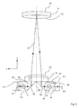
- Fig. 6 is essentially the representation of Fig. 2 corresponds, once again clarified, since in Fig. 6 additionally schematically the prisms 12 - 15 are drawn.
- the same elements are designated by the same reference numerals, wherein in Fig. 6 the tilting mirrors K3 and K5 are shown above the prisms 12-15, as shown in FIG Fig. 3 the case is.
- the on-light L3 is directed by means of the imaging optics 4 on the boundary surface of the prism 15 to the air gap, that the light by total internal reflection on the second tilting mirror matrix and the second image modulator 5 hits.
- the on-light L4 reflected by the second modulator 5 then passes perpendicular to the plane E in the y-direction through the wide prisms 15 and 14 and the gap therebetween, whereas the off-light L5 is at the angle of 48 ° is reflected relative to the Lot on the plane E of the module door 5 and after passing through the prisms 15 and 14 and the air gap therebetween meets a beam trap, not shown.
- the imaging optics 4 is designed so that it does not limit the maximum possible light conductance of the tilting mirror matrices 3, 5.
- the numerical aperture (sine of the maximum opening angle of the beam) in this case is 0.2 and the angle between the main beams of the imaging beam and the modulator normal is 24 °.
- the imaging optics 4 is designed for a usable wavelength range of 400 to 700 nm.
- the plano-convex lens 8 has a plane surface F1, which with the also flat rear surfaces 20, 21 of the prisms 13, 15, as best in Fig. 4 is visible, is cemented, and a convex surface F2.
- x, y and z denote the three Cartesian coordinates of a point lying on the surface F2 in the local area-related coordinate system.
- the local surface coordinate system of the surface F2 and thus the surface F2 is clockwise by 22.4 ° (in Fig. 5 ) is rotated about the x-axis of the local area coordinate system of the back surfaces 20, 21, which is in the Figures 3 - 5 is drawn.
- R, k and the coefficients C m, n are given in Table 1 below. For ease of illustration, in Table 1, the coefficients C m, n are denoted as C (m, n).
- the glass path of the on-light L3 from the top 16 of the second prism 13 or to the surface F2 is exactly as long as the glass path of the reflected on the mirror surface F4 on-light L3 from the surface F2 to the top 17 of the fourth prism 15, namely 102.8 mm.
- the second lens 9 is formed as an off-axis section of a lens having a first and second spherical interface, wherein the surface F3 is a section of the first spherical interface and the surface F4 is a section of the second spherical interface.
- the two spherical interfaces have the same radius of curvature of -375.75 mm and are spaced by 17.5 mm in the axial direction.
- the axial direction here is the z-direction of the local coordinate system of the surface F2 before its rotation by 22.4 °.
- the axial distance of the local coordinate origins of the surfaces F2 and F3 is 252.61 mm.
- the aperture stop of the imaging optics 4 is formed by the optically used region of the mirror surface F4 of the second lens 9.
- the edge of the optically used region of the mirror surface F4 lies here in a plane, which can therefore also be referred to as an aperture diaphragm plane.
- the aperture diaphragm plane encloses the normal of the plane in which the tilting axes of the tilting mirrors of the first modulator 3 lie, without the optical path convolutions through the prism 13, an angle not equal to 90 °.
- the glass lens 9 Since an off-axial section of the lens defined by the two spherical interfaces forms the glass lens 9, the glass lens 9 has a slightly wedge-shaped configuration.
- the two lenses 8, 9 and the prisms 12 to 15 are formed of the same material.
- the material BK7 with an Abbe number of 64.17 and a refractive index of 1.5168 at 587.6 nm is used.
- the position of the center of the surface F4 relative to the local coordinate system of the surface F2 can be indicated. There is a shift in the z-direction by 254.26 mm, in the y-direction by -107.99 mm with a subsequent tilting about the x-axis of the local coordinate system of the surface F2 by 16.7 ° instead.
- the z-axis of the local coordinate system of the surface F4 is thus not parallel to the normal of the modulator surface of the first tilting mirror matrix 3, but includes an angle between 0 and 90 ° with the normal.
- the surface F4 is decentered from the first tilting mirror matrix in the yz plane. This allows a very compact imaging optics with excellent imaging properties can be achieved. And so the distortion of the imaging optics 4 at each point of the second tilting mirror matrix 5 is less than 3 ⁇ m and thus less than a quarter of the width of the tilting mirror of the tilting mirror matrix 5.
- the tilt of the aperture stop can also be described such that the modulator plane E in the unfolded state is not parallel to the plane subtended by the x and y axes of the local coordinate system of the face F4, the center of the face F4 being the point of origin local coordinate system is.
- the first tilting mirror matrix 3 can be arranged on the second tilting mirror matrix 4, which are arranged in the same plane, at a beam angle (angle between the Normal to the modulator surface and the main rays of the light beam used for the intermediate image) are imaged with very high image quality.
- the beam angle can correspond to the maximum tilt angle of the tilting mirror.
- the dimensions of the areas F2-F4 are determined from the given dimensions of the image field (modulator areas), the numerical aperture and the design data of the optical elements, artificial vignetting of the imaging optics can be avoided.
- the tilted aperture diaphragm or the tilted pupils of the imaging optics 4 thus advantageously lead to imaging optics 4 with excellent imaging properties.
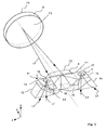
- Fig. 7 is a perspective view of the projector 1 according to Fig. 1 to 6 shown, in which for the beam separation module 11 only the glass path (without the performed optical path folds) is shown as a block, which passes through the on-light L3.
- Fig. 7 are the modulator surfaces, in each of which the tilt axes of the tilting mirror of the two modulators 3, 5 are located, the normals N1 and N2 located. Furthermore, the coordinate origin U1 of the free-form surface F2 is shown, and the optical axis OA1 of the surface F3 and the optical axis OA2 of the reflective surface F4 are shown. Out Fig. 7 It is readily apparent that the aperture diaphragm (optically used region of the mirror surface F4) or the aperture diaphragm plane AE, in which the edge of the optically used region of the mirror surface F4 lies, is not equal to 90 ° relative to the normal N1 of the modulator surface of the first tilting mirror matrix 3 includes.
- Fig. 7 still drawn the yz plane to which the imaging optics 4 is symmetrical.
- Fig. 8 is a modification of the projector 1 according to the invention in the same way as in Fig. 6 shown, wherein the same or similar elements are designated by the same reference numerals.
- the imaging optics 4 in the projector 1 according to Fig. 8 no backside mirrored lenses, but only a curved one Mirror surface F5 (imaging mirror) with an optical axis OA3.
- the angle between the aperture diaphragm (imaging mirror F5) and the normal N1 is not equal to 90 °.
- the illumination modulator 3 is exposed to white light.
- the light source 2 emits colored light.
- it can deliver time-sequentially different colored light, such. B. red, green and blue light.
- a multicolored image can be generated by the time-sequential display of red, green and blue partial color images. It only needs to be done so fast the color change that a viewer can not separate the successive temporally projected partial color images, so that the viewer can perceive only the superposition and thus the multi-color image.
- the time-sequential generation of the differently colored illumination light can be carried out in a customary manner, for example by means of a color wheel (not shown) between the light source 2 and the illumination modulator 3.
- the overlay and color separation can be carried out by means of dichroic layers.
- This embodiment with six modulators is of course much more complicated than the embodiment described in connection with Fig. 1 to 7 , However, with such an embodiment, a brighter color image can be produced.
Landscapes
- Physics & Mathematics (AREA)
- General Physics & Mathematics (AREA)
- Engineering & Computer Science (AREA)
- Multimedia (AREA)
- Signal Processing (AREA)
- Projection Apparatus (AREA)
- Transforming Electric Information Into Light Information (AREA)
- Lenses (AREA)
- Mechanical Light Control Or Optical Switches (AREA)
Applications Claiming Priority (6)
| Application Number | Priority Date | Filing Date | Title |
|---|---|---|---|
| US7513308P | 2008-06-24 | 2008-06-24 | |
| DE102008029785.2A DE102008029785B4 (de) | 2008-06-24 | 2008-06-24 | Projektionssystem |
| DE102008029789A DE102008029789B4 (de) | 2008-06-24 | 2008-06-24 | Projektionssystem |
| DE102008029788.7A DE102008029788B4 (de) | 2008-06-24 | 2008-06-24 | Projektionssystem |
| DE102008029787.9A DE102008029787B4 (de) | 2008-06-24 | 2008-06-24 | Projektionssystem |
| PCT/EP2009/004531 WO2009156130A1 (de) | 2008-06-24 | 2009-06-23 | Projektionssystem |
Publications (2)
| Publication Number | Publication Date |
|---|---|
| EP2294483A1 EP2294483A1 (de) | 2011-03-16 |
| EP2294483B1 true EP2294483B1 (de) | 2012-09-26 |
Family
ID=41128913
Family Applications (1)
| Application Number | Title | Priority Date | Filing Date |
|---|---|---|---|
| EP09768979A Active EP2294483B1 (de) | 2008-06-24 | 2009-06-23 | Projektionssystem |
Country Status (5)
| Country | Link |
|---|---|
| US (2) | US8500290B2 (pt) |
| EP (1) | EP2294483B1 (pt) |
| JP (1) | JP5990380B2 (pt) |
| BR (1) | BRPI0910156B1 (pt) |
| WO (1) | WO2009156130A1 (pt) |
Families Citing this family (14)
| Publication number | Priority date | Publication date | Assignee | Title |
|---|---|---|---|---|
| DE102008029786B4 (de) * | 2008-06-24 | 2013-10-24 | Carl Zeiss Ag | Projektor und Verfahren zum Projizieren eines Bildes |
| JP5990380B2 (ja) | 2008-06-24 | 2016-09-14 | カール・ツァイス・アクチェンゲゼルシャフトCarl Zeiss Ag | 投影システム |
| WO2009156129A1 (de) | 2008-06-24 | 2009-12-30 | Carl Zeiss Ag | Projektor und verfahren zum projizieren eines bildes |
| KR20120131359A (ko) * | 2011-05-25 | 2012-12-05 | 삼성전자주식회사 | 릴레이 렌즈들이 생략된 영상투사장치 |
| DE102012217329B4 (de) | 2012-09-25 | 2024-03-21 | Carl Zeiss Jena Gmbh | Projektionsvorrichtung |
| TWI465772B (zh) * | 2013-03-27 | 2014-12-21 | Delta Electronics Inc | 立體顯示光源與立體顯示裝置 |
| US20140327885A1 (en) * | 2013-05-01 | 2014-11-06 | David Joseph Mansur | Apparatus for obtaining enhanced contrast in projected images using digital micromirror devices |
| JP2015219434A (ja) * | 2014-05-20 | 2015-12-07 | キヤノン株式会社 | 照明光学系および画像投射装置 |
| US9485491B2 (en) * | 2014-12-15 | 2016-11-01 | Test Research, Inc. | Optical system |
| DE102016100592B4 (de) * | 2016-01-14 | 2018-12-13 | Carl Zeiss Jena Gmbh | Projektor zum Projizieren von Bildern |
| JP6732631B2 (ja) | 2016-10-31 | 2020-07-29 | 株式会社ジャパンディスプレイ | 表示装置 |
| EP3647856B1 (en) * | 2018-10-31 | 2022-11-09 | Ricoh Company, Ltd. | Image projection apparatus and mobile object |
| KR102192941B1 (ko) * | 2019-03-26 | 2020-12-18 | 주식회사 레티널 | 복수개의 증강 현실용 화상을 이용한 증강 현실용 광학 장치 |
| DE102020125572A1 (de) | 2020-09-30 | 2022-03-31 | Carl Zeiss Jena Gmbh | Projektionssystem |
Family Cites Families (65)
| Publication number | Priority date | Publication date | Assignee | Title |
|---|---|---|---|---|
| US4330282A (en) | 1979-11-05 | 1982-05-18 | Syntex (U.S.A.) Inc. | Rotor driven vibratory device having rotor centralization means and vibrational mode selection means associated therewith |
| US5192946A (en) | 1989-02-27 | 1993-03-09 | Texas Instruments Incorporated | Digitized color video display system |
| US5214420A (en) | 1989-02-27 | 1993-05-25 | Texas Instruments Incorporated | Spatial light modulator projection system with random polarity light |
| US5079544A (en) | 1989-02-27 | 1992-01-07 | Texas Instruments Incorporated | Standard independent digitized video system |
| US5287096A (en) | 1989-02-27 | 1994-02-15 | Texas Instruments Incorporated | Variable luminosity display system |
| US5175637A (en) | 1990-04-05 | 1992-12-29 | Raychem Corporation | Displays having improved contrast |
| US5075789A (en) | 1990-04-05 | 1991-12-24 | Raychem Corporation | Displays having improved contrast |
| EP0467048B1 (en) | 1990-06-29 | 1995-09-20 | Texas Instruments Incorporated | Field-updated deformable mirror device |
| US5481321A (en) | 1991-01-29 | 1996-01-02 | Stereographics Corp. | Stereoscopic motion picture projection system |
| US5231388A (en) | 1991-12-17 | 1993-07-27 | Texas Instruments Incorporated | Color display system using spatial light modulators |
| US5384659A (en) * | 1992-04-20 | 1995-01-24 | Mitsubishi Denki Kabushiki Kaisha | Condenser lens, polarizing element, light source apparatus, and projection display apparatus |
| AT399751B (de) | 1992-07-03 | 1995-07-25 | Voest Alpine Bergtechnik | Teilschnittschrämmaschine mit ankerbohr- und setzeinrichtungen |
| US5559629A (en) | 1994-08-19 | 1996-09-24 | Tamarack Scientific Co., Inc. | Unit magnification projection system and method |
| GB2317290B (en) | 1996-09-11 | 2000-12-06 | Seos Displays Ltd | Image display apparatus |
| DE19723208A1 (de) | 1997-06-03 | 1998-12-10 | Ldt Gmbh & Co | Vorrichtung zum Intensitätsmodulieren eines Lichtbündels, ein Herstellungsverfahren für diese, ein Verfahren zum Intensitätsmodulieren eines Lichtbündels sowie Verwendungen von der Vorrichtung |
| CA2402197A1 (en) | 2000-03-15 | 2001-09-20 | Steven Charles Read | Improvements in dmd-based image display systems |
| CA2376411C (en) | 2000-03-31 | 2009-01-20 | Imax Corporation | Digital projection equipment and techniques |
| US7050122B2 (en) | 2000-07-03 | 2006-05-23 | Imax Corporation | Equipment and techniques for increasing the dynamic range of a projection system |
| US6643069B2 (en) | 2000-08-31 | 2003-11-04 | Texas Instruments Incorporated | SLM-base color projection display having multiple SLM's and multiple projection lenses |
| ATE353528T1 (de) * | 2000-12-29 | 2007-02-15 | Texas Instruments Inc | Optischer motor für slm-anzeigesysteme mit auflichtschirm oder durchlichtschirm |
| JP4348409B2 (ja) | 2001-02-27 | 2009-10-21 | ドルビー ラボラトリーズ ライセンシング コーポレイション | 高ダイナミック・レンジ表示装置 |
| DE10127620A1 (de) * | 2001-06-07 | 2002-12-12 | Zeiss Carl Jena Gmbh | Anordnung zum Projizieren eines mehrfarbigen Bildes auf eine Projektionsfläche |
| US6863401B2 (en) | 2001-06-30 | 2005-03-08 | Texas Instruments Incorporated | Illumination system |
| US7002533B2 (en) | 2001-08-17 | 2006-02-21 | Michel Sayag | Dual-stage high-contrast electronic image display |
| DE10140806A1 (de) | 2001-08-20 | 2003-03-06 | Zeiss Carl Jena Gmbh | 1:1-Abbildungsoptik sowie Verwendung einer solchen bei einer Projektionsanordnung und einer Aufnahmeanordnung |
| US7064740B2 (en) | 2001-11-09 | 2006-06-20 | Sharp Laboratories Of America, Inc. | Backlit display with improved dynamic range |
| US6961194B2 (en) | 2001-12-31 | 2005-11-01 | Texas Instruments Incorporated | Integrated TIR prism and lens element |
| EP2378507B1 (en) | 2002-03-13 | 2018-05-09 | Dolby Laboratories Licensing Corporation | Light emitting element failure compensation in a display |
| US6817717B2 (en) | 2002-09-19 | 2004-11-16 | Hewlett-Packard Development Company, L.P. | Display system with low and high resolution modulators |
| GB0228089D0 (en) | 2002-12-02 | 2003-01-08 | Seos Ltd | Dynamic range enhancement of image display apparatus |
| EP1576829B1 (en) | 2002-12-04 | 2014-05-21 | Thomson Licensing | Two-stage projector architecture |
| BR0316729A (pt) | 2002-12-04 | 2005-10-11 | Thomson Licensing Sa | Arquitetura de projeção com dois estágios |
| CN100505892C (zh) | 2002-12-04 | 2009-06-24 | 汤姆森许可贸易公司 | 具有增强的对比度的光阀系统 |
| TW200419184A (en) | 2003-03-19 | 2004-10-01 | Delta Electronics Inc | Multiple reflection mirror module |
| TWI239428B (en) | 2003-04-18 | 2005-09-11 | Benq Corp | Projection display apparatus |
| US6940645B2 (en) * | 2003-04-22 | 2005-09-06 | Eastman Kodak Company | Monocentric autostereoscopic optical apparatus with a spherical gradient-index ball lens |
| GB0311128D0 (en) | 2003-05-14 | 2003-06-18 | Seos Ltd | Image display apparatus |
| JP3757221B2 (ja) | 2003-08-14 | 2006-03-22 | Necビューテクノロジー株式会社 | 投写型表示装置 |
| GB2408646B (en) | 2003-11-28 | 2008-11-26 | Seos Ltd | Image Display Apparatus with Night Vision Goggle Compatibility |
| JP4158757B2 (ja) | 2003-12-24 | 2008-10-01 | セイコーエプソン株式会社 | 光学表示装置及び投射型表示装置 |
| US6850352B1 (en) | 2004-01-08 | 2005-02-01 | Hewlett-Packard Development Company, L.P. | Method and system for generating color using a low-resolution spatial color modulator and a high-resolution modulator |
| JP2005215475A (ja) | 2004-01-30 | 2005-08-11 | Seiko Epson Corp | プロジェクタ |
| WO2005104565A1 (en) | 2004-03-26 | 2005-11-03 | Thomson Licensing | Two-stage projector architecture |
| WO2005115012A1 (en) | 2004-05-11 | 2005-12-01 | Thomson Licensing | System for using larger arc lamps with smaller imagers in a two-stage system comprising two imagers in series |
| US7090353B1 (en) | 2004-08-14 | 2006-08-15 | Lockheed Martin Corp. | System and method for improved digital projection |
| US7175289B2 (en) | 2004-09-15 | 2007-02-13 | Hewlett-Packard Development Company, L.P. | Optical relay |
| US7136209B2 (en) * | 2004-10-20 | 2006-11-14 | Hewlett-Packard Development Company, L.P. | Light modulators |
| US7136210B2 (en) | 2004-10-21 | 2006-11-14 | Hewlett-Packard Development Company, L.P. | Light modulator |
| JP2006235161A (ja) * | 2005-02-24 | 2006-09-07 | Seiko Epson Corp | プロジェクタ |
| JP4158776B2 (ja) | 2005-03-09 | 2008-10-01 | セイコーエプソン株式会社 | 画像表示装置及びプロジェクタ |
| US20060244921A1 (en) | 2005-04-28 | 2006-11-02 | Childers Winthrop D | Contrast enhancement by selectively using light attenuating modulator |
| US7503659B2 (en) * | 2005-06-02 | 2009-03-17 | 3M Innovative Properties Company | Multiple location illumination system and projection display system employing same |
| US20090225236A1 (en) | 2005-06-30 | 2009-09-10 | Youngshik Yoon | High Contrast Transmissive Lcd Imager |
| US7621641B1 (en) * | 2005-08-02 | 2009-11-24 | Eastman Kodak Company | High luminance display apparatus using LCD panel |
| US20070076172A1 (en) | 2005-10-05 | 2007-04-05 | Scott Lerner | Projection assembly |
| US7136205B1 (en) | 2005-10-24 | 2006-11-14 | Itt Manufacturing Enterprises, Inc. | Volume-phase holographic diffraction grating optimized for the ultraviolet spectral region |
| DE102005061182B4 (de) * | 2005-12-21 | 2020-03-19 | Carl Zeiss Jena Gmbh | Beleuchtungseinrichtung zur Farbbildprojektion |
| US7832870B2 (en) * | 2006-07-06 | 2010-11-16 | Texas Instruments Incorporated | Projection system using reflected light from a color wheel |
| FR2899980A1 (fr) | 2006-09-27 | 2007-10-19 | Thomson Licensing Sas | Dispositif d'affichage d'images par projection comprenant deux modulateurs spatiaux relies par un systeme relais catadioptrique |
| WO2008068257A1 (fr) | 2006-12-05 | 2008-06-12 | Thomson Licensing | Dispositif d'affichage d'images par projection a deux etages de modulation |
| US8226246B2 (en) * | 2007-12-04 | 2012-07-24 | Silicon Quest Kabushiki-Kaisha | Apparatus and method, both for controlling spatial light modulator |
| JP5194870B2 (ja) * | 2008-02-19 | 2013-05-08 | コニカミノルタアドバンストレイヤー株式会社 | 画像表示装置及び投影装置 |
| JP5990380B2 (ja) | 2008-06-24 | 2016-09-14 | カール・ツァイス・アクチェンゲゼルシャフトCarl Zeiss Ag | 投影システム |
| DE102008029786B4 (de) | 2008-06-24 | 2013-10-24 | Carl Zeiss Ag | Projektor und Verfahren zum Projizieren eines Bildes |
| WO2009156129A1 (de) | 2008-06-24 | 2009-12-30 | Carl Zeiss Ag | Projektor und verfahren zum projizieren eines bildes |
-
2009
- 2009-06-23 JP JP2011515195A patent/JP5990380B2/ja active Active
- 2009-06-23 BR BRPI0910156A patent/BRPI0910156B1/pt active IP Right Grant
- 2009-06-23 US US13/001,377 patent/US8500290B2/en active Active
- 2009-06-23 EP EP09768979A patent/EP2294483B1/de active Active
- 2009-06-23 WO PCT/EP2009/004531 patent/WO2009156130A1/de not_active Ceased
-
2013
- 2013-04-16 US US13/863,567 patent/US8696143B2/en active Active
Also Published As
| Publication number | Publication date |
|---|---|
| JP5990380B2 (ja) | 2016-09-14 |
| JP2011525996A (ja) | 2011-09-29 |
| US20130242274A1 (en) | 2013-09-19 |
| WO2009156130A1 (de) | 2009-12-30 |
| EP2294483A1 (de) | 2011-03-16 |
| US8696143B2 (en) | 2014-04-15 |
| US8500290B2 (en) | 2013-08-06 |
| BRPI0910156A2 (pt) | 2016-01-19 |
| BRPI0910156B1 (pt) | 2019-12-24 |
| US20110176120A1 (en) | 2011-07-21 |
Similar Documents
| Publication | Publication Date | Title |
|---|---|---|
| EP2294483A1 (de) | Projektionssystem | |
| DE69523125T2 (de) | Flüssigkristall-projektionsanzeigesysteme | |
| DE69805645T2 (de) | Anzeigegerät mit einem gitter-lichtventilarray und interferometrisches optisches system | |
| DE69207362T2 (de) | Beleuchtungsgerät und damit versehener Projektor | |
| EP2711761B1 (de) | Projektionsvorrichtung | |
| EP1016274B1 (de) | Anordnung, bei der von einer lichtquelle aus licht auf eine fläche gerichtet wird | |
| DE69716875T2 (de) | Bildprojektionssystem zur grossbilddarstellung | |
| DE69523300T2 (de) | Bauelement zur strahlzusammenführung und eine dieses enthaltende farbbildprojektionsvorrichtung | |
| DE112018002005T5 (de) | Bildanzeigevorrichtung | |
| WO1995003676A1 (de) | Projektionssystem zum projizieren eines farbvideobilds und zugehörige transformationsoptik | |
| DE68909641T2 (de) | Projektionsdarstellungsgerät. | |
| DE102014118490A1 (de) | Anzeigevorrichtungen | |
| DE102008020858B4 (de) | Projektionssystem für ein optisches Anzeigegerät sowie Head-mounted Display mit einem solchen | |
| EP1145069A2 (de) | Anordnung, bei der von einer lichtquelle aus licht auf eine fläche gerichtet wird | |
| EP1554890A1 (de) | ANORDNUNG ZUM PROJIZIEREN EINES BILDES AUF EINE PROJEKTIONSFLÄCHE UND ZUGEH RIGE TRANSFORMATIONSOPTIK | |
| DE102008029788B4 (de) | Projektionssystem | |
| DE102008029789B4 (de) | Projektionssystem | |
| DE102004001389B4 (de) | Anordnung und Vorrichtung zur Minimierung von Randverfärbungen bei Videoprojektionen | |
| DE102008029785B4 (de) | Projektionssystem | |
| DE102008029787B4 (de) | Projektionssystem | |
| WO2004109365A1 (de) | Projektionsvorrichtung | |
| EP3978983B1 (de) | Projektionssystem | |
| EP2225610B1 (de) | Verfahren und vorrichtung zum projizieren eines bildes auf eine projektionsfläche | |
| DE19907345B4 (de) | Vorrichtung zum Abbilden eines als Raster von Bildpunkten darstellbaren Bildes auf einem Schirm | |
| DE102024115881A1 (de) | Holographische Anzeigevorrichtung mit zwei Displays zur Breitbildanzeige |
Legal Events
| Date | Code | Title | Description |
|---|---|---|---|
| PUAI | Public reference made under article 153(3) epc to a published international application that has entered the european phase |
Free format text: ORIGINAL CODE: 0009012 |
|
| 17P | Request for examination filed |
Effective date: 20101215 |
|
| AK | Designated contracting states |
Kind code of ref document: A1 Designated state(s): AT BE BG CH CY CZ DE DK EE ES FI FR GB GR HR HU IE IS IT LI LT LU LV MC MK MT NL NO PL PT RO SE SI SK TR |
|
| AX | Request for extension of the european patent |
Extension state: AL BA RS |
|
| 17Q | First examination report despatched |
Effective date: 20110519 |
|
| DAX | Request for extension of the european patent (deleted) | ||
| REG | Reference to a national code |
Ref country code: DE Ref legal event code: R079 Ref document number: 502009004911 Country of ref document: DE Free format text: PREVIOUS MAIN CLASS: G03B0021200000 Ipc: G03B0021140000 |
|
| GRAP | Despatch of communication of intention to grant a patent |
Free format text: ORIGINAL CODE: EPIDOSNIGR1 |
|
| RIC1 | Information provided on ipc code assigned before grant |
Ipc: H04N 5/74 20060101ALI20120503BHEP Ipc: H04N 9/31 20060101ALI20120503BHEP Ipc: G03B 21/20 20060101ALI20120503BHEP Ipc: G03B 21/14 20060101AFI20120503BHEP |
|
| GRAS | Grant fee paid |
Free format text: ORIGINAL CODE: EPIDOSNIGR3 |
|
| GRAA | (expected) grant |
Free format text: ORIGINAL CODE: 0009210 |
|
| RIN1 | Information on inventor provided before grant (corrected) |
Inventor name: NIETEN, CHRISTOPH Inventor name: GEISSLER, ENRICO Inventor name: RUDOLPH, GUENTER Inventor name: PRETORIUS, MARCO |
|
| AK | Designated contracting states |
Kind code of ref document: B1 Designated state(s): AT BE BG CH CY CZ DE DK EE ES FI FR GB GR HR HU IE IS IT LI LT LU LV MC MK MT NL NO PL PT RO SE SI SK TR |
|
| REG | Reference to a national code |
Ref country code: GB Ref legal event code: FG4D Free format text: NOT ENGLISH |
|
| REG | Reference to a national code |
Ref country code: CH Ref legal event code: EP |
|
| REG | Reference to a national code |
Ref country code: AT Ref legal event code: REF Ref document number: 577310 Country of ref document: AT Kind code of ref document: T Effective date: 20121015 |
|
| REG | Reference to a national code |
Ref country code: IE Ref legal event code: FG4D Free format text: LANGUAGE OF EP DOCUMENT: GERMAN |
|
| REG | Reference to a national code |
Ref country code: DE Ref legal event code: R096 Ref document number: 502009004911 Country of ref document: DE Effective date: 20121122 |
|
| PG25 | Lapsed in a contracting state [announced via postgrant information from national office to epo] |
Ref country code: FI Free format text: LAPSE BECAUSE OF FAILURE TO SUBMIT A TRANSLATION OF THE DESCRIPTION OR TO PAY THE FEE WITHIN THE PRESCRIBED TIME-LIMIT Effective date: 20120926 Ref country code: NO Free format text: LAPSE BECAUSE OF FAILURE TO SUBMIT A TRANSLATION OF THE DESCRIPTION OR TO PAY THE FEE WITHIN THE PRESCRIBED TIME-LIMIT Effective date: 20121226 Ref country code: HR Free format text: LAPSE BECAUSE OF FAILURE TO SUBMIT A TRANSLATION OF THE DESCRIPTION OR TO PAY THE FEE WITHIN THE PRESCRIBED TIME-LIMIT Effective date: 20120926 Ref country code: LT Free format text: LAPSE BECAUSE OF FAILURE TO SUBMIT A TRANSLATION OF THE DESCRIPTION OR TO PAY THE FEE WITHIN THE PRESCRIBED TIME-LIMIT Effective date: 20120926 |
|
| REG | Reference to a national code |
Ref country code: LT Ref legal event code: MG4D Effective date: 20120926 |
|
| REG | Reference to a national code |
Ref country code: NL Ref legal event code: VDEP Effective date: 20120926 |
|
| PG25 | Lapsed in a contracting state [announced via postgrant information from national office to epo] |
Ref country code: LV Free format text: LAPSE BECAUSE OF FAILURE TO SUBMIT A TRANSLATION OF THE DESCRIPTION OR TO PAY THE FEE WITHIN THE PRESCRIBED TIME-LIMIT Effective date: 20120926 Ref country code: GR Free format text: LAPSE BECAUSE OF FAILURE TO SUBMIT A TRANSLATION OF THE DESCRIPTION OR TO PAY THE FEE WITHIN THE PRESCRIBED TIME-LIMIT Effective date: 20121227 Ref country code: SI Free format text: LAPSE BECAUSE OF FAILURE TO SUBMIT A TRANSLATION OF THE DESCRIPTION OR TO PAY THE FEE WITHIN THE PRESCRIBED TIME-LIMIT Effective date: 20120926 Ref country code: SE Free format text: LAPSE BECAUSE OF FAILURE TO SUBMIT A TRANSLATION OF THE DESCRIPTION OR TO PAY THE FEE WITHIN THE PRESCRIBED TIME-LIMIT Effective date: 20120926 |
|
| PG25 | Lapsed in a contracting state [announced via postgrant information from national office to epo] |
Ref country code: ES Free format text: LAPSE BECAUSE OF FAILURE TO SUBMIT A TRANSLATION OF THE DESCRIPTION OR TO PAY THE FEE WITHIN THE PRESCRIBED TIME-LIMIT Effective date: 20130106 Ref country code: IS Free format text: LAPSE BECAUSE OF FAILURE TO SUBMIT A TRANSLATION OF THE DESCRIPTION OR TO PAY THE FEE WITHIN THE PRESCRIBED TIME-LIMIT Effective date: 20130126 Ref country code: NL Free format text: LAPSE BECAUSE OF FAILURE TO SUBMIT A TRANSLATION OF THE DESCRIPTION OR TO PAY THE FEE WITHIN THE PRESCRIBED TIME-LIMIT Effective date: 20120926 Ref country code: RO Free format text: LAPSE BECAUSE OF FAILURE TO SUBMIT A TRANSLATION OF THE DESCRIPTION OR TO PAY THE FEE WITHIN THE PRESCRIBED TIME-LIMIT Effective date: 20120926 Ref country code: EE Free format text: LAPSE BECAUSE OF FAILURE TO SUBMIT A TRANSLATION OF THE DESCRIPTION OR TO PAY THE FEE WITHIN THE PRESCRIBED TIME-LIMIT Effective date: 20120926 Ref country code: CZ Free format text: LAPSE BECAUSE OF FAILURE TO SUBMIT A TRANSLATION OF THE DESCRIPTION OR TO PAY THE FEE WITHIN THE PRESCRIBED TIME-LIMIT Effective date: 20120926 |
|
| PG25 | Lapsed in a contracting state [announced via postgrant information from national office to epo] |
Ref country code: PT Free format text: LAPSE BECAUSE OF FAILURE TO SUBMIT A TRANSLATION OF THE DESCRIPTION OR TO PAY THE FEE WITHIN THE PRESCRIBED TIME-LIMIT Effective date: 20130128 Ref country code: SK Free format text: LAPSE BECAUSE OF FAILURE TO SUBMIT A TRANSLATION OF THE DESCRIPTION OR TO PAY THE FEE WITHIN THE PRESCRIBED TIME-LIMIT Effective date: 20120926 Ref country code: PL Free format text: LAPSE BECAUSE OF FAILURE TO SUBMIT A TRANSLATION OF THE DESCRIPTION OR TO PAY THE FEE WITHIN THE PRESCRIBED TIME-LIMIT Effective date: 20120926 |
|
| PG25 | Lapsed in a contracting state [announced via postgrant information from national office to epo] |
Ref country code: DK Free format text: LAPSE BECAUSE OF FAILURE TO SUBMIT A TRANSLATION OF THE DESCRIPTION OR TO PAY THE FEE WITHIN THE PRESCRIBED TIME-LIMIT Effective date: 20120926 Ref country code: BG Free format text: LAPSE BECAUSE OF FAILURE TO SUBMIT A TRANSLATION OF THE DESCRIPTION OR TO PAY THE FEE WITHIN THE PRESCRIBED TIME-LIMIT Effective date: 20121226 |
|
| PLBE | No opposition filed within time limit |
Free format text: ORIGINAL CODE: 0009261 |
|
| STAA | Information on the status of an ep patent application or granted ep patent |
Free format text: STATUS: NO OPPOSITION FILED WITHIN TIME LIMIT |
|
| PG25 | Lapsed in a contracting state [announced via postgrant information from national office to epo] |
Ref country code: IT Free format text: LAPSE BECAUSE OF FAILURE TO SUBMIT A TRANSLATION OF THE DESCRIPTION OR TO PAY THE FEE WITHIN THE PRESCRIBED TIME-LIMIT Effective date: 20120926 |
|
| 26N | No opposition filed |
Effective date: 20130627 |
|
| REG | Reference to a national code |
Ref country code: DE Ref legal event code: R097 Ref document number: 502009004911 Country of ref document: DE Effective date: 20130627 |
|
| PG25 | Lapsed in a contracting state [announced via postgrant information from national office to epo] |
Ref country code: CY Free format text: LAPSE BECAUSE OF FAILURE TO SUBMIT A TRANSLATION OF THE DESCRIPTION OR TO PAY THE FEE WITHIN THE PRESCRIBED TIME-LIMIT Effective date: 20120926 |
|
| BERE | Be: lapsed |
Owner name: CARL ZEISS A.G. Effective date: 20130630 |
|
| PG25 | Lapsed in a contracting state [announced via postgrant information from national office to epo] |
Ref country code: MC Free format text: LAPSE BECAUSE OF FAILURE TO SUBMIT A TRANSLATION OF THE DESCRIPTION OR TO PAY THE FEE WITHIN THE PRESCRIBED TIME-LIMIT Effective date: 20120926 |
|
| REG | Reference to a national code |
Ref country code: CH Ref legal event code: PL |
|
| REG | Reference to a national code |
Ref country code: IE Ref legal event code: MM4A |
|
| PG25 | Lapsed in a contracting state [announced via postgrant information from national office to epo] |
Ref country code: BE Free format text: LAPSE BECAUSE OF NON-PAYMENT OF DUE FEES Effective date: 20130630 |
|
| PG25 | Lapsed in a contracting state [announced via postgrant information from national office to epo] |
Ref country code: LI Free format text: LAPSE BECAUSE OF NON-PAYMENT OF DUE FEES Effective date: 20130630 Ref country code: CH Free format text: LAPSE BECAUSE OF NON-PAYMENT OF DUE FEES Effective date: 20130630 Ref country code: IE Free format text: LAPSE BECAUSE OF NON-PAYMENT OF DUE FEES Effective date: 20130623 |
|
| PG25 | Lapsed in a contracting state [announced via postgrant information from national office to epo] |
Ref country code: MT Free format text: LAPSE BECAUSE OF FAILURE TO SUBMIT A TRANSLATION OF THE DESCRIPTION OR TO PAY THE FEE WITHIN THE PRESCRIBED TIME-LIMIT Effective date: 20120926 |
|
| PG25 | Lapsed in a contracting state [announced via postgrant information from national office to epo] |
Ref country code: TR Free format text: LAPSE BECAUSE OF FAILURE TO SUBMIT A TRANSLATION OF THE DESCRIPTION OR TO PAY THE FEE WITHIN THE PRESCRIBED TIME-LIMIT Effective date: 20120926 |
|
| PG25 | Lapsed in a contracting state [announced via postgrant information from national office to epo] |
Ref country code: MK Free format text: LAPSE BECAUSE OF FAILURE TO SUBMIT A TRANSLATION OF THE DESCRIPTION OR TO PAY THE FEE WITHIN THE PRESCRIBED TIME-LIMIT Effective date: 20120926 Ref country code: HU Free format text: LAPSE BECAUSE OF FAILURE TO SUBMIT A TRANSLATION OF THE DESCRIPTION OR TO PAY THE FEE WITHIN THE PRESCRIBED TIME-LIMIT; INVALID AB INITIO Effective date: 20090623 Ref country code: LU Free format text: LAPSE BECAUSE OF NON-PAYMENT OF DUE FEES Effective date: 20130623 |
|
| REG | Reference to a national code |
Ref country code: FR Ref legal event code: PLFP Year of fee payment: 8 |
|
| REG | Reference to a national code |
Ref country code: FR Ref legal event code: PLFP Year of fee payment: 9 |
|
| REG | Reference to a national code |
Ref country code: FR Ref legal event code: PLFP Year of fee payment: 10 |
|
| REG | Reference to a national code |
Ref country code: DE Ref legal event code: R082 Ref document number: 502009004911 Country of ref document: DE Representative=s name: PATENTANWAELTE GEYER, FEHNERS & PARTNER MBB, DE Ref country code: DE Ref legal event code: R081 Ref document number: 502009004911 Country of ref document: DE Owner name: CARL ZEISS JENA GMBH, DE Free format text: FORMER OWNER: CARL ZEISS AG, 73447 OBERKOCHEN, DE |
|
| REG | Reference to a national code |
Ref country code: GB Ref legal event code: 732E Free format text: REGISTERED BETWEEN 20181115 AND 20181130 |
|
| REG | Reference to a national code |
Ref country code: AT Ref legal event code: PC Ref document number: 577310 Country of ref document: AT Kind code of ref document: T Owner name: CARL ZEISS JENA GMBH, DE Effective date: 20181220 |
|
| PGFP | Annual fee paid to national office [announced via postgrant information from national office to epo] |
Ref country code: DE Payment date: 20250618 Year of fee payment: 17 |
|
| PGFP | Annual fee paid to national office [announced via postgrant information from national office to epo] |
Ref country code: GB Payment date: 20250618 Year of fee payment: 17 |
|
| PGFP | Annual fee paid to national office [announced via postgrant information from national office to epo] |
Ref country code: FR Payment date: 20250624 Year of fee payment: 17 |
|
| PGFP | Annual fee paid to national office [announced via postgrant information from national office to epo] |
Ref country code: AT Payment date: 20250620 Year of fee payment: 17 |