EP2294532B1 - Encoding device for data storage media and method for encoding data storage media - Google Patents
Encoding device for data storage media and method for encoding data storage media Download PDFInfo
- Publication number
- EP2294532B1 EP2294532B1 EP09757499A EP09757499A EP2294532B1 EP 2294532 B1 EP2294532 B1 EP 2294532B1 EP 09757499 A EP09757499 A EP 09757499A EP 09757499 A EP09757499 A EP 09757499A EP 2294532 B1 EP2294532 B1 EP 2294532B1
- Authority
- EP
- European Patent Office
- Prior art keywords
- encoding
- transport direction
- transport
- stations
- loading
- Prior art date
- Legal status (The legal status is an assumption and is not a legal conclusion. Google has not performed a legal analysis and makes no representation as to the accuracy of the status listed.)
- Active
Links
Images


Classifications
-
- G—PHYSICS
- G06—COMPUTING OR CALCULATING; COUNTING
- G06K—GRAPHICAL DATA READING; PRESENTATION OF DATA; RECORD CARRIERS; HANDLING RECORD CARRIERS
- G06K13/00—Conveying record carriers from one station to another, e.g. from stack to punching mechanism
- G06K13/02—Conveying record carriers from one station to another, e.g. from stack to punching mechanism the record carrier having longitudinal dimension comparable with transverse dimension, e.g. punched card
- G06K13/07—Transporting of cards between stations
- G06K13/073—Transporting of cards between stations with continuous movement
Definitions
- US 4,827,425 describes a system for personalization of smart cards.
- the personalization takes place at a plurality of sequentially arranged coding stations.
- the majority of the coding stations is arranged either on a horizontal or a vertical turntable.
- the turntable is rotated in one direction only and data transmission to the coding stations is via an optical link.
- the present invention has the object to provide a coding device for data carriers for encoding of data carriers, which has a simple structure without sliding contacts for the power and data supply to coding stations, and maintains the position and orientation of the data carrier during encoding. It is a further object of the present invention to provide a method of encoding data carriers which provides simplified transmission of data to the individual data carriers to be encoded by maintaining the data carrier alignment with respect to its top and bottom sides before and after the encoding process and a simple structure of a coding device allows.
- the first data carrier after they were previously introduced in the coding stations or the associated storage compartments or the rotary device were loaded with these, and a coding has already been made, they are discharged again, while the second data carrier in the intermediate occupied storage compartments or Coding stations are pushed.
- a simultaneous loading and unloading would take place, again preferably only every second receiving compartment being occupied during a rotational movement of the rotating device in the second transport direction and the intermediate still free receiving compartments during a rotational movement in the opposite third transport direction.
- a transport device 11 ensures the transport of chip cards 12 in the transport direction 12a within a transport plane 12b.
- This transport of the smart cards 12 follows to a loading and unloading station 14, the receiving compartments 17 by means of rod-like guide elements 16a and 16b or appropriately trained pins and arranged above stamp surfaces can be pressed by a drive element from top to bottom.
- the drive element which belongs to the loading and unloading station 14 is moved upwards.
- the example vertically oriented cylinder 14 of the loading and unloading station is mounted directly or indirectly on the underside of the upper plate 2 and thus arranged stationary relative to the rotating turntable.
- each second receiving compartment 17a takes place during a rotational movement in the direction 13b.
- the first, third, fifth, seventh etc. Tray is each occupied by a chip card. This is carried out during a rotational movement in the direction 13b until a nearly 360 ° rotation of the turntable 7 has taken place.
- every third or only every fourth receiving compartment or each receiving compartment can be loaded during such a rotational movement in one direction.
Landscapes
- Physics & Mathematics (AREA)
- General Physics & Mathematics (AREA)
- Engineering & Computer Science (AREA)
- Theoretical Computer Science (AREA)
- Specific Conveyance Elements (AREA)
- Signal Processing For Digital Recording And Reproducing (AREA)
Abstract
Description
Die Erfindung betrifft eine Codiervorrichtung für Datenträger, insbesondere Chipkarten, mit einer Transporteinrichtung zum Transport einer Mehrzahl an Datenträgern in eine erste Transportrichtung einer Transportebene und einer Dreheinrichtung mit einer Mehrzahl an ringartig angeordneten Codierstationen, die jeweils ein Aufnahmefach zum Aufnehmen jeweils eines Datenträgers aufweisen, gemäß dem Oberbegriff des Patentanspruches 8 sowie ein Verfahren zum Codieren von Datenträgern gemäß dem Oberbegriff des Patentanspruches 1.The invention relates to a coding device for data carriers, in particular chip cards, with a transport device for transporting a plurality of data carriers in a first transport direction of a transport plane and a rotating device with a plurality of annularly arranged Codierstationen, each having a receptacle for receiving a respective data carrier, according to the The preamble of
Aus
Das Rad dreht sich fortlaufend in eine vorgegeben Drehrichtung, wobei diese Drehrichtung immer beibehalten wird. Für eine derartige fortlaufende Drehung in eine vorgegebene Richtung muss das Rad Schleifkontakte und Schleifringe aufweisen, um eine Stromzu- und Abführung sowie einen Datentransfer zu dem Rad und zu den einzelnen Kontaktierungsvorrichtungen, innerhalb welcher ein Datentransfer von oder zu der eingefügten Chipkarte erfolgt, verwendet werden, da ansonsten ein sich ständig fortsetzendes Verdrehen und Aufwickeln der hierfür notwendigen Drahtverbindungen erfolgen würde. Wenn keine Schleifkontakte oder Schleifringe hierzu verwendet werden, würde dies letztendlich zu einem Bruch der eingebauten Drähte und somit zu einer Strom- und Datentransferunterbrechung führen. Zudem sind derartige Schleifringe mit höheren Herstellungskosten, höheren Wartungskosten und höheren Reparaturkosten verbunden.The wheel turns continuously in a given direction of rotation, this direction of rotation is always maintained. For such continuous rotation in a given direction, the wheel must have sliding contacts and slip rings to allow for power supply and discharge, as well as data transfer to the wheel and to the individual contacting devices within which data transfer from or to the inserted smart card occurs. otherwise there would be a constantly continuing twisting and winding the necessary wire connections. Failure to use slip contacts or slip rings would ultimately result in breakage of the built-in wires and thus a power and data transfer break. In addition, such slip rings are associated with higher manufacturing costs, higher maintenance costs and higher repair costs.
Zudem führen derartig ausgerichtete Drehplatten bzw. Drehräder, an deren Außenrand die Kontaktierungsvorrichtungen angeordnet sind und die vertikal zu der Transportrichtung des zuvor erfolgten Transportes ausgerichtet sind dazu, dass die Karten, wenn sie auf der einen Seite der vertikal ausgerichteten Drehplatte bzw. Drehscheibe aufgenommen werden und auf der anderen Seite abgelegt werden, in umgedrehter Ausrichtung abgelegt werden, also wird die zuvor nach unten gerichtete Rückseite nach oben gewandt. Oft ist ein derartiges Umdrehen der Karten für die nachfolgende Bearbeitung nicht erwünscht.In addition, such oriented turntables or rotary wheels, on the outer edge of the contacting devices are arranged and which are aligned vertically to the transport direction of the previous transport to the fact that the cards when they are taken on one side of the vertically oriented turntable or turntable and be placed on the other side, stored in an inverted orientation, so will the previously downward facing back turned upwards. Often, such reversal of the cards for subsequent processing is not desired.
Demzufolge liegt der vorliegenden Erfindung die Aufgabe zugrunde, eine Codiervorrichtung für Datenträger zum Codieren von Datenträgern zur Verfügung zu stellen, die einen einfachen Aufbau ohne Schleifkontakte für die Strom- und Datenzufuhr zu Codierstationen aufweist, und die Lage und Ausrichtung der Datenträger während der Codierung beibehält. Des weiteren liegt der vorliegenden Erfindung die Aufgabe zugrunde, ein Verfahren zum Codieren von Datenträgern zur Verfügung zu stellen welches eine vereinfachte Übertragung von Daten zu den einzelnen zu codierenden Datenträgern durch die Beibehaltung der Datenträgerausrichtung hinsichtlich ihrer Ober- und Unterseiten vor und nach dem Codiervorgang und einen einfachen Aufbau einer Codiervorrichtung ermöglicht.Accordingly, the present invention has the object to provide a coding device for data carriers for encoding of data carriers, which has a simple structure without sliding contacts for the power and data supply to coding stations, and maintains the position and orientation of the data carrier during encoding. It is a further object of the present invention to provide a method of encoding data carriers which provides simplified transmission of data to the individual data carriers to be encoded by maintaining the data carrier alignment with respect to its top and bottom sides before and after the encoding process and a simple structure of a coding device allows.
Diese Aufgabe wird verfahrensseitig durch die Merkmale des Patentanspruches 1 und vorrichtungsseitig durch die Merkmale des Patentanspruches 8 gelöst.This object is achieved on the method side by the features of claim 1 and device side by the features of
Ein wesentlicher Punkt der Erfindung liegt darin, dass bei einer Codiervorrichtung die Datenträger, insbesondere Chipkarten, mit einer Transporteinrichtung zum Transport einer Mehrzahl an Datenträgern in eine erste Transportrichtung einer Transportebene und einer Dreheinrichtung mit einer Mehrzahl an ringartig angeordneten Codierstationen, die jeweils ein Aufnahmefach zum Aufnehmen jeweils eines Datenträgers aufweisen, eine Drehachse der Dreheinrichtung senkrecht zu der Transportebene und der ersten Transportrichtung ausgerichtet aufweisen. Die Dreheinrichtung ist um die Drehachse in eine zweite Transporteinrichtung und eine der zweiten Transportrichtung entgegengesetzten dritten Transportrichtung drehbar gelagert, so dass sowohl eine vorwärtsgerichtete Drehbewegung als auch eine rückwärtsgerichtete Drehbewegung der Dreheinrichtung möglich ist. Sofern dies mit einer gegenüber der Dreheinrichtung stationär angeordneten Be- und Entladestation zum Be- und Entladen der Datenträger von der Transporteinrichtung in die Codierstationen und von den Codierstationen auf die Transporteinrichtung und/oder eine weitere Transporteinrichtung kombiniert wird, entsteht hierdurch die Möglichkeit, dass an der vorzugsweise einzigen Be- und Entladestation die Codierstationen einzeln sowohl in vorwärts- als auch in rückwärtsgerichteter Drehbewegung Be- und/oder Entladen werden können, wobei eine vollständige 360°-Drehung vermieden wird. Dies hat zur Folge, dass nicht mehr weiterhin Schleifkontakte und Schleifringe verwendet werden müssen, um einen Strom- und Datentransfer zu den einzelnen Codierstationen sicher zu stellen, wie es der Fall wäre, wenn sich die Dreheinrichtung fortlaufend immer in eine Richtung weiterdrehen würde. Vielmehr kann durch die vorwärts- und rückwärtsgerichtete Drehbewegung erreicht werden, dass eine direkte Drahtverbindung zu den einzelnen Codierstationen besteht, die sich immer wieder auf- und abwickeln, sofern einer vorwärtsgerichteten zweiten Transportrichtung bzw. Drehrichtung eine dritte rückwärtsgerichtete Transportrichtung bzw. Drehrichtung erfolgt.An essential point of the invention is that in a coding device, the data carriers, in particular smart cards, with a transport device for transporting a plurality of data carriers in a first transport direction of a transport plane and a rotating device with a plurality of annularly arranged coding stations, each a receptacle for receiving each having a data carrier, an axis of rotation of the rotary device aligned perpendicular to the transport plane and the first transport direction. The rotating device is rotatably mounted about the axis of rotation in a second transport device and the second transport direction opposite to the third transport direction, so that both a forward rotational movement and a reverse rotational movement of the rotating device is possible. If this is combined with a relation to the rotating stationary stationary loading and unloading station for loading and unloading of the disk from the transport device in the coding stations and from the coding stations on the transport device and / or another transport device, this creates the possibility that at the preferably single loading and unloading the coding stations can be individually loading and / or unloading in both forward and backward rotational movement, with a full 360 ° rotation is avoided. As a result, it is no longer necessary to use sliding contacts and slip rings to ensure current and data transfer to the individual coding stations, as would be the case if the rotating device were to continue to rotate continuously in one direction. Rather, it can be achieved by the forward and backward rotational movement, that there is a direct wire connection to the individual coding stations, which are always up and Unwind, provided a forward direction of transport direction or direction of rotation is a third direction of transport direction or direction of rotation.
Durch die Ausbildung einer stationär angeordneten Be- und Entladestation, welche sich nicht mit der Dreheinrichtung mitdreht erübrigt sich eine Mehrzahl an entsprechend ausgebildeten Be- und Entladeeinrichtungen bzw. -elementen, die jeder einzelnen Codierstation zugeordnet wären und sich mit der Dreheinrichtung mitdrehen würden. Vielmehr kann auf diese Mehrzahl an sich mitdrehenden Be- und Entladeeinrichtungen bzw. -elementen verzichtet werden. Hieraus ergibt sich eine Kostenreduzierung während der Herstellung einer derartigen Vorrichtung und eine diesbezügliche Materialeinsparung bei der Herstellung.By forming a stationarily arranged loading and unloading station, which does not rotate with the rotating device, a plurality of correspondingly designed loading and unloading devices or elements which would be associated with each individual coding station and would rotate with the rotating device are unnecessary. Rather, it is possible to dispense with this plurality of co-rotating loading and unloading devices or elements. This results in a cost reduction during the manufacture of such a device and a related material savings in the production.
Die Ausbildung der Dreheinrichtung mit einer Drehachse, deren Ausrichtung senkrecht zu der Transportebene und der ersten Transportrichtung des zuvor erfolgten, vorzugsweise in einer Ebene des Transportes hat neben dem Effekt, dass die Datenträger, insbesondere Chipkarten, mit der gewünschten Oberfläche wieder abgelegt werden, die Wirkung, dass eine platzsparende Anordnung der Codiervorrichtung innerhalb einer größeren Anlage, die vorzugsweise eine Personalisierungsmaschine darstellt, möglich ist. Denn bedingt durch die horizontale Ausrichtung der Dreheinrichtung, die auch als Drehteller bezeichnet werden kann, wird eine Gesamtanlage mit einer geringen Bauhöhe ermöglicht, da ein derartiger Drehteller nicht in vertikaler Ausrichtung "riesenradartig" innerhalb der Anlage angeordnet ist.The formation of the rotating device with an axis of rotation, the orientation perpendicular to the transport plane and the first transport direction of the previously made, preferably in a plane of transport has the effect next to the effect that the disk, in particular smart cards are stored again with the desired surface, the effect in that a space-saving arrangement of the coding device within a larger system, which is preferably a personalization machine, is possible. Because due to the horizontal orientation of the rotating device, which can also be referred to as a turntable, an overall system with a low height is possible because such a turntable is not arranged in a vertical orientation "giant wheel" within the system.
Die Be- und Entladestation ist vorzugsweise mit mindestens mit einem in Richtung der Drehachse ein- und ausfahrbaren Antriebselement, vorzugsweise ein Zylinderelement, Motor o.a., zum Ein- und Ausfahren von jeweils einem Aufnahmefach versehen. Hierbei kann das Antriebselement mit mindestens einem an jedem Aufnahmefach angebrachten stangenartigen Führungselement wechselwirken, wobei das stangenartige Führungselement mit dem ein- und ausfahrbaren Aufnahmefach verschiebbar ist. Sofern das Aufnahmefach also unterhalb zwei sich vertikal erstreckender stangenartiger Führungselemente angeordnet ist und an diesen befestigt ist, können diese stangenartige Führungselemente mittels des von oben wirkenden Antriebselementes nach unten gedrückt werden, wobei in dieser Stellung des Aufnahmefaches eine Be- oder Entladung des Aufnahmefaches mit einer Chipkarte erfolgt, und anschließend wieder nach oben gefahren werden.The loading and unloading station is preferably provided with at least one drive element which can be moved in and out in the direction of the axis of rotation, preferably a cylinder element, motor or the like, for insertion and withdrawal of a respective receiving compartment. In this case, the drive element interact with at least one mounted on each receptacle rod-like guide element, wherein the rod-like guide member with the retractable and retractable receiving compartment is displaceable. Insofar as the receiving compartment is thus arranged underneath two vertically extending rod-like guide elements and fastened thereto, these rod-like guide elements can be pressed downwards by means of the drive element acting from above, wherein in this position of the receiving compartment a loading or unloading of the receiving compartment with a chip card takes place, and then moved back up.
Vorzugsweise findet ein derartiges nach oben Fahren der stangenartigen Führungselemente und damit auch des Aufnahmefaches dadurch statt, dass die stangenartigen Federelemente und/oder das Aufnahmefach federbeaufschlagt sind/ist, um hierdurch das Aufnahmefach selbsttätig bei eingefahrenen Antriebselement einfahren zu lassen.Preferably, such an upward movement of the rod-like guide elements and thus also of the receiving compartment takes place in that the rod-like spring elements and / or the receiving tray are spring loaded / is to thereby retract the receiving tray automatically retracted drive element.
Gemäß einem Verfahren der vorliegenden Erfindung, in dem mit einer Transporteinrichtung eine Mehrzahl an Chipkarten in einer ersten Transportrichtung einer Transportebene transportiert werden, und eine Dreheinrichtung in eine zweite Transportrichtung und eine der zweiten Transportrichtung entgegengesetzten dritten Transportrichtung gedreht wird, wird die Dreheinrichtung sowohl in die zweite als auch in die dritte Transportrichtung um weniger als 360° gedreht. Die Dreheinrichtung wird dabei um eine senkrecht zu der Transportebene und der ersten Transportrichtung ausgerichtete Drehachse gedreht, wobei eine Mehrzahl an der Dreheinrichtung ringartig angeordneter und an der Dreheinrichtung befestigter Codierstationen, die jeweils ein Aufnahmefach aufweisen, jeweils mit einer Chipkarte beladen werden. Ein erster Teil der Codierstationen wird taktweise, in einer bestimmten Reihenfolge der Codierstationen, beladen, und die Dreheinrichtung wird zwischen den einzelnen Beladevorgängen des ersten Teils der Codierstationen in die zweite Transportrichtung gedreht. Ein zweiter Teil der Codierstationen wird taktweise, in einer bestimmten Reihenfolge der Codierstationen, beladen, die Dreheinrichtung zwischen den einzelnen Beladevorgängen des zweiten Teils der Codierstationen wird in die dritte Transportrichtung gedreht, und die Chipkarten in den Codierstationen werden codiert.According to a method of the present invention, in which a plurality of chip cards are transported in a first transport direction of a transport plane with a transport device, and a rotation device is rotated in a second transport direction and a third transport direction opposite to the second transport direction, the rotation device becomes both into the second transport direction as well as rotated in the third transport direction by less than 360 °. The rotating device is thereby rotated about an axis of rotation aligned perpendicular to the transport plane and the first transport direction, wherein a plurality of the rotating device ring-like arranged and attached to the rotating coding stations, each having a receiving compartment, each loaded with a smart card. A first part of the coding stations is loaded in cycles, in a specific order of the coding stations, and the rotating device is rotated between the individual loading operations of the first part of the coding stations in the second transport direction. A second part of the coding stations is loaded in cycles, in a specific order of the coding stations, the rotating device between the individual loading operations of the second part of the coding stations is rotated in the third transport direction, and the chip cards in the coding stations are coded.
In einem Verfahren kann die Dreheinrichtung taktweise in die zweite Transportrichtung derart gedreht werden, dass sie mit jedem n-ten Aufnahmefach zur Aufnahme erster Datenträger an der Be- und Entladestation anhält und in die dritte Transportrichtung derart drehbar ist, dass sie mit jedem (n+1)-ten Aufnahmefach zur Aufnahme zweiter Datenträger an der Be- und Entladestation anhält. Hierbei enthält n die ungeraden Zahlennummem, die bei einer ringförmigen Durchnummerierung der Aufnahmefächer, die ringartig an der Dreheinrichtung bzw. dem Drehteller angeordnet sind, entstehen. Dies bedeutet, dass zum Beispiel nur jedes zweite Aufnahmefach bei einer Drehung der Dreheinrichtung in die zweite Transportrichtung mit einer Chipkarte beladen wird, wohingegen die dazwischenliegenden Aufnahmefächer vorerst unbesetzt bleiben. Eine derartige Beladung findet so lange statt, bis die Dreheinrichtung eine nahezu 360°-Drehung durchgeführt hat, wobei hierbei 360° nicht überschritten werden. Anschließend findet die entgegengesetzte Drehung in die dritte Transportrichtung statt, um während dieser Drehung jedes zwischen den bereits besetzten Aufnahmefächern liegende Aufnahmefach mit einer weiteren Chipkarte zu beladen. Erst wenn dieser Beladungsvorgang vollständig abgeschlossen ist, und eine Codierung der einzelnen Chipkarten, welche während des Beladevorgangs bereits starten kann, beendet ist, findet eine Entladung der Aufnahmefächer an der gleichen Be- und Entladestation oder gegebenenfalls an einer weiteren Be- und Entladestation statt. Alternativ können die ersten Datenträger, nachdem diese zuvor in den Codierstationen bzw. den dazugehörigen Aufnahmefächern eingeführt wurden bzw. die Dreheinrichtung mit diesen beladen wurden, und eine Codierung bereits erfolgt ist, diese wieder entladen werden, während die zweiten Datenträger in den dazwischenliegenden besetzten Aufnahmefächern bzw. Codierstationen hineingeschoben werden. Somit würde in diesem Fall ein zeitgleicher Be- und Entladevorgang stattfinden, wobei wiederum vorzugsweise lediglich jedes zweite Aufnahmefach bei einer Drehbewegung der Dreheinrichtung in die zweite Transportrichtung und die dazwischenliegenden noch freien Aufnahmefächer bei einer Drehbewegung in die entgegengesetzte dritte Transportrichtung belegt werden.In one method, the rotating device can be cyclically rotated in the second transport direction such that it stops with each nth receiving compartment for receiving first data carrier at the loading and unloading station and is rotatable in the third transport direction such that it with each (n + 1) -th receiving compartment for receiving second disk stops at the loading and unloading station. In this case, n contains the odd number numbers, which arise in the case of an annular numbering of the receiving compartments, which are arranged in an annular manner on the rotary device or on the turntable. This means that, for example, only every second receiving compartment is loaded with a rotation of the rotating device in the second transport direction with a chip card, whereas the intermediate receiving compartments remain unoccupied for the time being. Such loading takes place until the rotating device has performed a nearly 360 ° rotation, in which case 360 ° are not exceeded. Subsequently, the opposite rotation takes place in the third transport direction to load during this rotation each lying between the already occupied storage compartments receiving compartment with another smart card. Only when this loading process is completed, and a coding of the individual smart cards, which can already start during the loading process, is completed, finds a discharge of the receiving compartments at the same loading and unloading station or optionally at a further loading and unloading station. Alternatively, the first data carrier, after they were previously introduced in the coding stations or the associated storage compartments or the rotary device were loaded with these, and a coding has already been made, they are discharged again, while the second data carrier in the intermediate occupied storage compartments or Coding stations are pushed. Thus, in this case a simultaneous loading and unloading would take place, again preferably only every second receiving compartment being occupied during a rotational movement of the rotating device in the second transport direction and the intermediate still free receiving compartments during a rotational movement in the opposite third transport direction.
Vorteilhaft kann die Reheinfolge der geladenen Karten während und nach dem Codiervorgang aufrechterhalten bleiben. Selbst wenn eine schlechte Karte vor oder während des Codiervorgangs identifiziert werden würde, kann die Reihenfolge aufrechterhalten bleiben. Somit befinden sich die Karten in einem sortierten Zustand.Advantageously, the reordering of the loaded cards can be maintained during and after the encoding process. Even if a bad card were identified before or during the encoding process, the order can be maintained. Thus, the cards are in a sorted state.
Selbstverständlich ist auch denkbar, dass die Aufnahmefächer in einer anderen Reihenfolge be- und entladen werden, wie beispielsweise das Beladen sämtlicher Aufnahmefächer über eine erste 180°-Drehung und das Beladen sämtlicher Aufnahmefächer innerhalb einer zweiten darauf folgenden 180°-Drehung der Dreheinrichtung, wobei die Dreheinrichtung sich in die zweite Transportrichtung über die ersten 180° und die zweiten 180° dreht. Anschließend würde bei einer rückwärtsgerichteten Drehbewegung bzw. während der dritten Transportrichtung der Dreheinrichtung eine komplette Entladung der Aufnahmefächer stattfinden. Somit würde bei einer vorwärtsgerichteten Drehbewegung über nahezu 360° eine Beladung sämtlicher Aufnahmefächer und bei einer rückwärtsgerichteten Drehbewegung über nahezu 360° eine Entladung der Aufnahmefächer erfolgen. Vorzugsweise ist die Dreheinrichtung sowohl in die zweite als auch in die dritte Transportrichtung um weniger als 360° drehbar, um die Anbringung von den Schleifringen und Schleifkontakten zu vermeiden.Of course, it is also conceivable that the receiving compartments are loaded and unloaded in a different order, such as the loading of all receiving compartments over a first 180 ° rotation and the loading of all receiving compartments within a second subsequent 180 ° rotation of the rotating device, said Rotary device rotates in the second transport direction over the first 180 ° and the second 180 °. Subsequently, a complete discharge of the receiving compartments would take place in a reverse rotational movement or during the third transport direction of the rotating device. Thus, in a forward rotational movement over almost 360 °, a loading of all storage compartments and a backward rotational movement over almost 360 ° discharge of the receiving compartments would be done. Preferably, the rotator is rotatable less than 360 ° in both the second and third transport directions to avoid attachment of the slip rings and sliding contacts.
Weitere vorteilhafte Ausführungsformen ergeben sich aus den Unteransprüchen.Further advantageous embodiments will become apparent from the dependent claims.
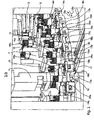
Vorteile und Zweckmäßigkeiten sind der nachfolgenden Beschreibung in Verbindung mit der Zeichnung zu entnehmen. Hierbei zeigen:
- Fig. 1
- In einer schematischen perspektivischen Darstellung eine Codiervorrichtung gemäß einer Ausführungsform der Erfindung;
- Fig. 2
- in einer schematischen Ausschnittsdarstellung die Codiervorrichtung gemäß der Ausführungsform der Erfindung; und
- Fig. 3
- eine perspektivische Darstellung der Codiervorrichtung gemäß der Ausführungsform der Erfindung in einem hochgeklappten Zustand.
- Fig. 1
- In a schematic perspective view of a coding device according to an embodiment of the invention;
- Fig. 2
- in a schematic sectional view of the coding device according to the embodiment of the invention; and
- Fig. 3
- a perspective view of the coding device according to the embodiment of the invention in a folded-up state.
In
Ein Antrieb der Drehachse 3 und damit des Drehtellers 7, vorzugsweise taktweise, erfolgt mittels eines Motors 5, der über einen Keilriemen 6 mit der Drehachse 3 verbunden ist.A drive of the rotation axis 3 and thus of the
Sowohl die obere Platte 2 als auch der Drehteller 7 und die weiteren Einrichtungen sind auf Standbeinen 8, 9 und 10 und gegebenenfalls weiteren Standbeinen angeordnet.Both the upper plate 2 and the
Eine Transporteinrichtung 11 sorgt für den Transport von Chipkarten 12 in Transportrichtung 12a innerhalb einer Transportebene 12b. Dieser Transport der Chipkarten 12 folgt zu einer Be- und Entladestation 14, die Aufnahmefächer 17 mittels stangenartiger Führungselemente 16a und 16b bzw. entsprechend ausgebildeter Stifte und darüber angeordneter Stempelflächen durch ein Antriebselement von oben nach unten gedrückt werden können. Sobald die Aufnahmefächer nach unten gedrückt sind, erfolgt die Zuführung bzw. Beladung mit einer Chipkarte 12. Anschließend wird das Antriebselement, welches zu der Be- und Entladestation 14 gehört nach oben gefahren. Durch eine entsprechende Federbeaufschlagung der Aufnahmefächer oder der stangenartigen Führungselement 16a und 16b wird hierdurch ein selbstständiges nach oben Fahren der Aufnahmefächer 17 erfolgen und somit ein Anordnen der Chipkarten innerhalb der eigentlichen Codierstation zur nachfolgenden Codierung der Chipkarten.A
Der Drehteller 7 kann sowohl in eine vorwärtsgerichtete Drehbewegung 13a als auch in eine rückwärtsgerichtete Drehbewegung 13b gedreht werden.The
Der beispielsweise vertikal ausgerichtete Zylinder 14 der Be- und Entladestation ist an der Unterseite der oberen Platte 2 direkt oder indirekt angebracht und somit gegenüber dem sich drehenden Drehteller stationär angeordnet.The example vertically oriented
Durch das nach oben Fahren des Aufnahmefaches findet eine Positionierung der Chipkarte in ihrer für die nachfolgende Codierung richtigen passenden Lage statt. Jede Codierstation mit einer Codiereinheit 18 weist Kontaktstifte, die hier nicht näher dargestellt sind, auf, um für eine sich anschließende Codierung mit der Chipkarte elektrisch in Kontakt zu treten und so gegebenenfalls ein Datentransfer durchzuführen. Selbstverständlich kann die eigentliche Codierung auch durch eine kontaktlose Datenübertragung, beispielsweise mittels Induktion erfolgen.By driving up the receiving compartment takes place positioning of the chip card in their correct coding for the subsequent encoding. Each coding station with an
Die Codierung an sich wird mittels nicht näher dargestellter Codierelektronikelemente, vorzugsweise in Form von Codierplatinen, innerhalb einer jeden Codierstation durchgeführt und dreht sich mit dem Drehteller 7 mit.The coding itself is performed by means not shown Codierelektronementemente, preferably in the form of Codierplatinen within each coding station and rotates with the
Aus
Sobald ein erstes Aufnahmefach 17a mit der Chipkarte 12 belegt ist, erfolgt nach entsprechenden nach oben Fahren des Antriebselementes 14 ein taktweises Weiterbewegen des Drehtellers 7 in eine Drehbewegungsrichtung 13b, wobei absichtlich das nachfolgende Aufnahmefach 17b nicht belegt wird, sondern erst wieder das darauf folgenden Aufnahmefach 17a. Somit findet eine Beladung jedes zweiten Aufnahmefaches 17a bei einer Drehbewegung in Richtung 13b statt. Dies bedeutet, dass das erste, dritte, fünfte, siebte usw. Fach jeweils mit einer Chipkarte belegt wird. Dies wird während einer Drehbewegung in Richtung 13b so lange durchgeführt, bis eine nahezu 360°-Drehung des Drehtellers 7 erfolgt ist. Selbstverständlich kann auch jedes dritte oder nur jedes vierte Aufnahmefach oder auch jedes Aufnahmefach während einer derartigen Drehbewegung in eine Richtung beladen werden.As soon as a
Nach einer nahezu vollständigen 360°-Drehung, die dann erfolgt ist, wenn das letzte Aufnahmefach vor Erreichen einer vollständigen 360°-Drehung im vorher beschriebenen Rhythmus unter Auslassung von jeweils dem zweiten Aufnahmefach beladen worden ist, findet eine Umkehrung der Drehbewegung in Richtung 13a statt. Bei dieser Drehbewegungsrichtung 13a werden nun die dazwischenliegenden noch unbesetzten Aufnahmefächer 17b mit den dazugehörigen Codierbauteilen 18b mit den Chipkarten wiederum durch taktweises Fortbewegen des Drehtellers 7 beladen. Hierdurch findet eine komplette Beladung bzw. Befüllung des Drehtellers 7 statt. Während und/oder nach einer derartigen Beladung des Drehtellers 7 mit den Chipkarten 12 findet das eigentliche Codierverfahren der Chipkarten statt. Nach Beendigung des Codierverfahrens werden die codierten Chipkarten aus den Aufnahmefächern wieder entladen, wobei dies entweder in umgekehrter Reihenfolge oder auch durch sukzessives Entladen der aufeinander folgenden Aufnahmefächer 17a und 17b erfolgen kann.After a nearly complete 360 ° rotation, which has taken place when the last receiving compartment has been loaded before reaching a complete 360 ° rotation in the previously described rhythm with the omission of the second receiving compartment, a reversal of the rotational movement takes place in the
Die entnommenen codierten Chipkarten werden dann entweder auf ein weiteres Transportband oder auf die bereits beschriebene Transporteinrichtung 11 abgelegt. Anschließend erfolgt wiederum ein Beladen des Drehtellers 7 mittels der mit der Transporteinrichtung 11 zugeführten Chipkarten 12, wobei die Transporteinrichtung 11 hierfür ein Vorschubelement 20 aufweist, welches die Chipkarten in die Aufnahmefächer 17, 17a und 17b hineinschiebt.The removed coded chip cards are then stored either on a further conveyor belt or on the
In
- 11
- Dreheinrichtungrotator
- 22
- Platteplate
- 33
- Drehachseaxis of rotation
- 55
- Motorengine
- 66
- Keilriemenfan belt
- 77
- Drehtellerturntable
- 8,9,108,9,10
- Standbeinemainstays
- 1111
- Transporteinrichtungtransport means
- 1212
- Chipkartesmart card
- 12a12a
- Transportrichtungtransport direction
- 12b12b
- Transportebenetransport plane
- 13a13a
- vorwärtsgerichtete Drehbewegungforward rotational movement
- 13b13b
- rückwärtsgerichtete Drehbewegungbackward rotational movement
- 1414
- Be- und EntladestationLoading and unloading station
- 1515
- Codierstationcoding station
- 16a, 16b16a, 16b
- Führungselementeguide elements
- 17,17a, 17b17,17a, 17b
- Aufnahmefächerreceiving compartments
- 18,18a, 18b18:18, 18b
- Codiereinrichtungenencoders
- 19a, 19b19a, 19b
- Bauelementecomponents
- 2020
- Vorschubelementfeed element
- 2121
- Teleskopstäbetelescopic rods
- 2222
- Pfeilarrow
Claims (14)
- Method for encoding chip cards, wherein- a plurality of chip cards (12) are transported with a transport device (11) in a first transport direction (12a) of a transport level (12b)- a rotation device (1) is rotated, in a second transport direction (13a)and in a third transport direction (13b) contrary to the second transport direction (13a), wherein the rotation device (1) is rotated in both the second and the third transport direction (13a, 13b),characterised in that- the rotation device is rotated around a pivot (3) which is aligned perpendicular to the transport level (12b) and to the first transport direction (12a), wherein- a plurality of encoding stations (18a, 18b) disposed circularly around the rotation device (1), each of which comprises a receptacle compartment (17a, 17b), are each loaded with a chip card (12), wherein- a first part of the encoding stations (18a) is loaded intermittently, in a particular sequence of the encoding stations (18a, 18b),- the rotation device (1) is rotated in the second transport direction (13a) between the individual loading operations of the first part of the encoding stations (18a),- a second part of the encoding stations (18b) is loaded intermittently, in a particular sequence of the encoding stations (18a, 18b),- the rotation device (1) is rotated in the third transport direction (13b) between the individual loading operations of the second part of the encoding stations (18b), and- the chip cards (12) are encoded in the encoding stations (18a, 18b).
- Method according to Claim 1, wherein the rotation device (1) is rotated alternately in the second and third transport direction (13a, 13b).
- Method according to Claim 1, wherein the encoding stations (18a, 18b) are loaded by a stationarily disposed loading and unloading station (14).
- Method according to Claim 1, wherein the chip cards (12) in the first part of the encoding stations (18a) are not unloaded until the second part of the encoding stations (18b) has been completely loaded, and the chip cards (12) in the second part of the encoding stations (18b) are not unloaded until the first part of the encoding stations (18a) has been unloaded and reloaded.
- Method according to Claim 1, wherein the chip cards (12) are unloaded in the order in which they were loaded.
- Method according to Claim 1, wherein the first part of the encoding stations (18a) is completely loaded first, before the second part of the encoding stations (18b) is loaded.
- Method according to Claim 1, wherein the rotation device (1) rotates intermittently, in a particular sequence of the encoding stations (18a, 18b), in a second transport direction (13a), such that- it stops at a loading and unloading station (14) with every n-th receptacle compartment (17a) in order to pick up first chip cards (12), and- is rotated in a transport direction (13b) contrary to the second transport direction (13a) such that it stops at the loading and unloading station (14) with every (n+1)th receptacle compartment (17b) in order to pick up second chip cards (12), and wherein- "n" represents uneven numbers if the receptacle compartments (17a, 17b) are numbered radially.
- Encoding device for chip cards (12), comprising- a transport device (11) for transporting a plurality of chip cards (12) in a first transport direction (12a) of a transport plane (12b), wherein- a rotation device (1) can rotate around a pivot (3) in a second transport direction (13a) and in a third transport direction (13b) contrary to the second transport direction (13a), wherein said rotation device (1) can rotate in both the second and the third transport direction (13a, 13b)characterised in that the encoding device further comprises:- a rotation device (1) which comprises a plurality of circularly disposed encoding stations (18a, 18b), each of said stations comprising a receptacle compartment (17a, 17b) for holding a respective chip card (12), wherein- the pivot (3) of the rotation device (1) is aligned perpendicular to the transport plane (12b) and to the first transport direction (12a), and- the rotation device (1) is configured in order to execute the method defined in Claim 1.
- Encoding device according to Claim 8, wherein the rotation device (1) comprises a stationarily disposed loading and unloading station (14) for loading and unloading chip cards (12) from the transport device (11) into the encoding stations (18a, 18b) and from the encoding stations (18a, 18b) to the transport device (11) and/or a further transport device.
- Encoding device according to Claim 9, wherein the loading and unloading station (14) comprises at least one element that is extendable and retractable in the direction of the pivot (3) for extending and retracting each receptacle compartment (17a, 17b).
- Encoding device according to Claim 10, wherein the extendable and retractable element interacts with at least one rod-type guide element (16a, 16b) attached to each receptacle compartment (17a, 17b), wherein said rod-type guide element (16a, 16b) is moveable with the extendable and retractable receptacle compartment (17a, 17b).
- Encoding device according to Claim 10 or 11, wherein each receptacle compartment (17a, 17b) and/or each rod-type guide element (16a, 16b) is spring-loaded, so that the receptacle compartment (17) retracts automatically when the extendable and retractable element is retracted.
- Encoding device according to one of claims 8-12, wherein the rotation device (1) may be rotated in the second transport direction (13a) such that it stops at the loading and unloading station (14) with every n-th receptacle compartment (17a) in order to pick up first chip cards (12), and may be rotated in the third transport direction (13b) such that it stops at the loading and unloading station (14) with every (n+1)-th receptacle compartment (17b) in order to pick up second chip cards (12), wherein "n" comprises uneven numbers if the receptacle compartments (17; 17a, 17b) are numbered radially.
- Encoding device according to one of claims 8-12, wherein the rotation device (1) is pivotably mounted and has at least one telescopic rod (21).
Applications Claiming Priority (3)
| Application Number | Priority Date | Filing Date | Title |
|---|---|---|---|
| DE102008026464 | 2008-06-03 | ||
| DE102008051516A DE102008051516A1 (en) | 2008-06-03 | 2008-10-14 | Coding device for data carriers and method for coding data carriers |
| PCT/EP2009/056704 WO2009147118A1 (en) | 2008-06-03 | 2009-06-02 | Encoding device for data storage media and method for encoding data storage media |
Publications (2)
| Publication Number | Publication Date |
|---|---|
| EP2294532A1 EP2294532A1 (en) | 2011-03-16 |
| EP2294532B1 true EP2294532B1 (en) | 2012-05-09 |
Family
ID=41335047
Family Applications (1)
| Application Number | Title | Priority Date | Filing Date |
|---|---|---|---|
| EP09757499A Active EP2294532B1 (en) | 2008-06-03 | 2009-06-02 | Encoding device for data storage media and method for encoding data storage media |
Country Status (5)
| Country | Link |
|---|---|
| EP (1) | EP2294532B1 (en) |
| AT (1) | ATE557359T1 (en) |
| DE (1) | DE102008051516A1 (en) |
| WO (1) | WO2009147118A1 (en) |
| ZA (1) | ZA201008675B (en) |
Families Citing this family (5)
| Publication number | Priority date | Publication date | Assignee | Title |
|---|---|---|---|---|
| EP2776177A2 (en) * | 2011-11-11 | 2014-09-17 | BÖWE SYSTEC GmbH | Device and method for combining cards and card supports, for handling cards and/or for sorting cards from card holders |
| DE102012202740A1 (en) | 2012-02-22 | 2013-08-22 | Bundesdruckerei Gmbh | Document buffer for an identity document |
| WO2013177762A1 (en) * | 2012-05-30 | 2013-12-05 | Gemalto Technologies (Shanghai) Co., Ltd. | Smart card graphical and electrical personalization module and method of graphical and electrical personalization for smart cards |
| DE102017210731A1 (en) * | 2017-06-26 | 2018-12-27 | Bundesdruckerei Gmbh | Device and method for transporting document bodies and method and device for producing documents |
| DE102020128018A1 (en) * | 2020-10-23 | 2022-04-28 | Mühlbauer Gmbh & Co. Kg | DEVICE AND METHOD FOR PROCESSING DOCUMENTS |
Family Cites Families (10)
| Publication number | Priority date | Publication date | Assignee | Title |
|---|---|---|---|---|
| FR2602603B1 (en) * | 1986-08-08 | 1988-11-18 | Bonnemoy Marc | AUTOMATIC CARD PERSONALIZATION APPARATUS |
| US4827425A (en) | 1986-10-31 | 1989-05-02 | Thorn Emi Malco, Incorporated | System for personalization of integrated circuit microchip cards |
| DE19644306C2 (en) * | 1996-10-24 | 1999-04-08 | Kunz Gmbh | Device for personalizing identification cards |
| FR2746531B1 (en) | 1996-03-19 | 1998-05-22 | Leroux Gilles Sa | HIGH-THROUGHPUT PERSONALIZATION MACHINE |
| DE19634230A1 (en) * | 1996-08-23 | 1998-02-26 | Kubat Mechanik Gmbh | Reading and writing method and device for chip cards |
| DE19641892A1 (en) | 1996-10-10 | 1998-04-16 | Ods Gmbh & Co Kg | Production system for programming of microprocessor boards |
| FR2766945B1 (en) * | 1997-07-29 | 1999-10-29 | Leroux Gilles Sa | HIGH-THROUGHPUT PERSONALIZATION MACHINE |
| DE19840811C2 (en) * | 1998-09-07 | 2003-04-17 | Kunz Gmbh | Device for personalizing identification cards |
| FR2816738B1 (en) * | 2000-11-13 | 2003-02-14 | Gemplus Card Int | MACHINE AND METHOD FOR PERSONALIZING CHIP CARDS |
| DE10063313A1 (en) * | 2000-12-19 | 2002-06-27 | Atlantic Zeiser Gmbh | Process for processing, in particular reading, programming or the like, card-shaped information carriers |
-
2008
- 2008-10-14 DE DE102008051516A patent/DE102008051516A1/en not_active Withdrawn
-
2009
- 2009-06-02 EP EP09757499A patent/EP2294532B1/en active Active
- 2009-06-02 WO PCT/EP2009/056704 patent/WO2009147118A1/en not_active Ceased
- 2009-06-02 AT AT09757499T patent/ATE557359T1/en active
-
2010
- 2010-12-02 ZA ZA2010/08675A patent/ZA201008675B/en unknown
Also Published As
| Publication number | Publication date |
|---|---|
| EP2294532A1 (en) | 2011-03-16 |
| ATE557359T1 (en) | 2012-05-15 |
| WO2009147118A1 (en) | 2009-12-10 |
| ZA201008675B (en) | 2011-12-28 |
| DE102008051516A1 (en) | 2009-12-24 |
Similar Documents
| Publication | Publication Date | Title |
|---|---|---|
| EP3579987B1 (en) | Bending tool storage device and method for feeding a press brake | |
| EP3148884B1 (en) | Device and method for controlled orientation and/or rotation of containers | |
| DE4409558A1 (en) | Device for the transport of substrates | |
| DE102008046366A1 (en) | Centering unit for aligning at least two grouped vessels and method for aligning two grouped vessels | |
| EP0569689A2 (en) | Method and device for sorting bottles | |
| WO2007101649A1 (en) | Apparatus for bobbin removal | |
| DE202009012064U1 (en) | Device for conveying objects, labeling device, inspection device and rotary filler with such a conveying device | |
| EP2363288A1 (en) | Device and method for aligning objects | |
| AT520311A4 (en) | Method and device for the automated production of a stator of an electrical machine | |
| DE102007047596A1 (en) | Handling device for electronic components, in particular ICs, with a plurality of guided in an orbit circulation car | |
| EP2294532A1 (en) | Encoding device for data storage media and method for encoding data storage media | |
| DE3702265C2 (en) | Method and device for exchanging bobbins and sleeves on roving machines | |
| EP1892207A2 (en) | Device for distribution and/or sorting of rolls of material and their transfer and a method for transporting rolls of material | |
| WO2012019782A2 (en) | System and method for processing security or identification objects | |
| DE3403311A1 (en) | WINDING MACHINE FOR REELS | |
| DE3902063C2 (en) | ||
| DE19704200A1 (en) | Device for turning can bodies | |
| DE102005054300B3 (en) | Data carrier processing e.g. identifying, method, involves storing one of processed data carrier on space in transport device, and moving processing tower backwards into starting position after reaching end position | |
| DE10222620A1 (en) | Method for processing electrical components, in particular for processing semiconductor chips and electrical components, and device for carrying out the method | |
| CH672642A5 (en) | ||
| EP3323745B1 (en) | Container handling machine and method for handling containers | |
| EP0467101B1 (en) | Device for loading the spindles of a bobbin creel | |
| DE1760119A1 (en) | Equipment on wire stranding machines and procedures for their operation | |
| DE102004022744A1 (en) | Processing method, for information carriers, e.g. identification cards, involves programming integrated circuits while they are at rest relative to programming device | |
| DE102019110295A1 (en) | Textile machine producing cross-wound bobbins |
Legal Events
| Date | Code | Title | Description |
|---|---|---|---|
| PUAI | Public reference made under article 153(3) epc to a published international application that has entered the european phase |
Free format text: ORIGINAL CODE: 0009012 |
|
| 17P | Request for examination filed |
Effective date: 20101203 |
|
| AK | Designated contracting states |
Kind code of ref document: A1 Designated state(s): AT BE BG CH CY CZ DE DK EE ES FI FR GB GR HR HU IE IS IT LI LT LU LV MC MK MT NL NO PL PT RO SE SI SK TR |
|
| AX | Request for extension of the european patent |
Extension state: AL BA RS |
|
| 17Q | First examination report despatched |
Effective date: 20110428 |
|
| DAX | Request for extension of the european patent (deleted) | ||
| GRAP | Despatch of communication of intention to grant a patent |
Free format text: ORIGINAL CODE: EPIDOSNIGR1 |
|
| GRAS | Grant fee paid |
Free format text: ORIGINAL CODE: EPIDOSNIGR3 |
|
| GRAA | (expected) grant |
Free format text: ORIGINAL CODE: 0009210 |
|
| RIN1 | Information on inventor provided before grant (corrected) |
Inventor name: VALTA, THOMAS Inventor name: DIMPFL, MARTIN Inventor name: STEIF, RICHARD |
|
| AK | Designated contracting states |
Kind code of ref document: B1 Designated state(s): AT BE BG CH CY CZ DE DK EE ES FI FR GB GR HR HU IE IS IT LI LT LU LV MC MK MT NL NO PL PT RO SE SI SK TR |
|
| REG | Reference to a national code |
Ref country code: GB Ref legal event code: FG4D Free format text: NOT ENGLISH |
|
| REG | Reference to a national code |
Ref country code: AT Ref legal event code: REF Ref document number: 557359 Country of ref document: AT Kind code of ref document: T Effective date: 20120515 Ref country code: CH Ref legal event code: EP |
|
| REG | Reference to a national code |
Ref country code: IE Ref legal event code: FG4D Free format text: LANGUAGE OF EP DOCUMENT: GERMAN |
|
| REG | Reference to a national code |
Ref country code: NL Ref legal event code: T3 |
|
| REG | Reference to a national code |
Ref country code: DE Ref legal event code: R096 Ref document number: 502009003480 Country of ref document: DE Effective date: 20120705 |
|
| REG | Reference to a national code |
Ref country code: LT Ref legal event code: MG4D Effective date: 20120509 |
|
| PG25 | Lapsed in a contracting state [announced via postgrant information from national office to epo] |
Ref country code: CY Free format text: LAPSE BECAUSE OF FAILURE TO SUBMIT A TRANSLATION OF THE DESCRIPTION OR TO PAY THE FEE WITHIN THE PRESCRIBED TIME-LIMIT Effective date: 20120509 Ref country code: SE Free format text: LAPSE BECAUSE OF FAILURE TO SUBMIT A TRANSLATION OF THE DESCRIPTION OR TO PAY THE FEE WITHIN THE PRESCRIBED TIME-LIMIT Effective date: 20120509 Ref country code: PL Free format text: LAPSE BECAUSE OF FAILURE TO SUBMIT A TRANSLATION OF THE DESCRIPTION OR TO PAY THE FEE WITHIN THE PRESCRIBED TIME-LIMIT Effective date: 20120509 Ref country code: IS Free format text: LAPSE BECAUSE OF FAILURE TO SUBMIT A TRANSLATION OF THE DESCRIPTION OR TO PAY THE FEE WITHIN THE PRESCRIBED TIME-LIMIT Effective date: 20120909 Ref country code: LT Free format text: LAPSE BECAUSE OF FAILURE TO SUBMIT A TRANSLATION OF THE DESCRIPTION OR TO PAY THE FEE WITHIN THE PRESCRIBED TIME-LIMIT Effective date: 20120509 Ref country code: FI Free format text: LAPSE BECAUSE OF FAILURE TO SUBMIT A TRANSLATION OF THE DESCRIPTION OR TO PAY THE FEE WITHIN THE PRESCRIBED TIME-LIMIT Effective date: 20120509 Ref country code: NO Free format text: LAPSE BECAUSE OF FAILURE TO SUBMIT A TRANSLATION OF THE DESCRIPTION OR TO PAY THE FEE WITHIN THE PRESCRIBED TIME-LIMIT Effective date: 20120809 |
|
| PG25 | Lapsed in a contracting state [announced via postgrant information from national office to epo] |
Ref country code: LV Free format text: LAPSE BECAUSE OF FAILURE TO SUBMIT A TRANSLATION OF THE DESCRIPTION OR TO PAY THE FEE WITHIN THE PRESCRIBED TIME-LIMIT Effective date: 20120509 Ref country code: GR Free format text: LAPSE BECAUSE OF FAILURE TO SUBMIT A TRANSLATION OF THE DESCRIPTION OR TO PAY THE FEE WITHIN THE PRESCRIBED TIME-LIMIT Effective date: 20120810 Ref country code: PT Free format text: LAPSE BECAUSE OF FAILURE TO SUBMIT A TRANSLATION OF THE DESCRIPTION OR TO PAY THE FEE WITHIN THE PRESCRIBED TIME-LIMIT Effective date: 20120910 Ref country code: SI Free format text: LAPSE BECAUSE OF FAILURE TO SUBMIT A TRANSLATION OF THE DESCRIPTION OR TO PAY THE FEE WITHIN THE PRESCRIBED TIME-LIMIT Effective date: 20120509 Ref country code: HR Free format text: LAPSE BECAUSE OF FAILURE TO SUBMIT A TRANSLATION OF THE DESCRIPTION OR TO PAY THE FEE WITHIN THE PRESCRIBED TIME-LIMIT Effective date: 20120509 |
|
| BERE | Be: lapsed |
Owner name: MUHLBAUER A.G. Effective date: 20120630 |
|
| PG25 | Lapsed in a contracting state [announced via postgrant information from national office to epo] |
Ref country code: EE Free format text: LAPSE BECAUSE OF FAILURE TO SUBMIT A TRANSLATION OF THE DESCRIPTION OR TO PAY THE FEE WITHIN THE PRESCRIBED TIME-LIMIT Effective date: 20120509 Ref country code: MC Free format text: LAPSE BECAUSE OF NON-PAYMENT OF DUE FEES Effective date: 20120630 Ref country code: DK Free format text: LAPSE BECAUSE OF FAILURE TO SUBMIT A TRANSLATION OF THE DESCRIPTION OR TO PAY THE FEE WITHIN THE PRESCRIBED TIME-LIMIT Effective date: 20120509 Ref country code: SK Free format text: LAPSE BECAUSE OF FAILURE TO SUBMIT A TRANSLATION OF THE DESCRIPTION OR TO PAY THE FEE WITHIN THE PRESCRIBED TIME-LIMIT Effective date: 20120509 Ref country code: RO Free format text: LAPSE BECAUSE OF FAILURE TO SUBMIT A TRANSLATION OF THE DESCRIPTION OR TO PAY THE FEE WITHIN THE PRESCRIBED TIME-LIMIT Effective date: 20120509 |
|
| PG25 | Lapsed in a contracting state [announced via postgrant information from national office to epo] |
Ref country code: MK Free format text: LAPSE BECAUSE OF FAILURE TO SUBMIT A TRANSLATION OF THE DESCRIPTION OR TO PAY THE FEE WITHIN THE PRESCRIBED TIME-LIMIT Effective date: 20120509 |
|
| PLBE | No opposition filed within time limit |
Free format text: ORIGINAL CODE: 0009261 |
|
| STAA | Information on the status of an ep patent application or granted ep patent |
Free format text: STATUS: NO OPPOSITION FILED WITHIN TIME LIMIT |
|
| REG | Reference to a national code |
Ref country code: IE Ref legal event code: MM4A |
|
| 26N | No opposition filed |
Effective date: 20130212 |
|
| PG25 | Lapsed in a contracting state [announced via postgrant information from national office to epo] |
Ref country code: IE Free format text: LAPSE BECAUSE OF NON-PAYMENT OF DUE FEES Effective date: 20120602 Ref country code: ES Free format text: LAPSE BECAUSE OF FAILURE TO SUBMIT A TRANSLATION OF THE DESCRIPTION OR TO PAY THE FEE WITHIN THE PRESCRIBED TIME-LIMIT Effective date: 20120820 Ref country code: BE Free format text: LAPSE BECAUSE OF NON-PAYMENT OF DUE FEES Effective date: 20120630 |
|
| REG | Reference to a national code |
Ref country code: DE Ref legal event code: R097 Ref document number: 502009003480 Country of ref document: DE Effective date: 20130212 |
|
| PG25 | Lapsed in a contracting state [announced via postgrant information from national office to epo] |
Ref country code: BG Free format text: LAPSE BECAUSE OF FAILURE TO SUBMIT A TRANSLATION OF THE DESCRIPTION OR TO PAY THE FEE WITHIN THE PRESCRIBED TIME-LIMIT Effective date: 20120809 Ref country code: MT Free format text: LAPSE BECAUSE OF FAILURE TO SUBMIT A TRANSLATION OF THE DESCRIPTION OR TO PAY THE FEE WITHIN THE PRESCRIBED TIME-LIMIT Effective date: 20120509 |
|
| REG | Reference to a national code |
Ref country code: CH Ref legal event code: PL |
|
| PG25 | Lapsed in a contracting state [announced via postgrant information from national office to epo] |
Ref country code: LI Free format text: LAPSE BECAUSE OF NON-PAYMENT OF DUE FEES Effective date: 20130630 Ref country code: TR Free format text: LAPSE BECAUSE OF FAILURE TO SUBMIT A TRANSLATION OF THE DESCRIPTION OR TO PAY THE FEE WITHIN THE PRESCRIBED TIME-LIMIT Effective date: 20120509 Ref country code: CH Free format text: LAPSE BECAUSE OF NON-PAYMENT OF DUE FEES Effective date: 20130630 |
|
| PG25 | Lapsed in a contracting state [announced via postgrant information from national office to epo] |
Ref country code: LU Free format text: LAPSE BECAUSE OF NON-PAYMENT OF DUE FEES Effective date: 20120602 |
|
| PG25 | Lapsed in a contracting state [announced via postgrant information from national office to epo] |
Ref country code: HU Free format text: LAPSE BECAUSE OF FAILURE TO SUBMIT A TRANSLATION OF THE DESCRIPTION OR TO PAY THE FEE WITHIN THE PRESCRIBED TIME-LIMIT Effective date: 20090602 |
|
| REG | Reference to a national code |
Ref country code: DE Ref legal event code: R082 Ref document number: 502009003480 Country of ref document: DE Representative=s name: WUESTHOFF & WUESTHOFF, PATENTANWAELTE PARTG MB, DE Ref country code: DE Ref legal event code: R081 Ref document number: 502009003480 Country of ref document: DE Owner name: MUEHLBAUER GMBH & CO. KG, DE Free format text: FORMER OWNER: MUEHLBAUER AG, 93426 RODING, DE |
|
| REG | Reference to a national code |
Ref country code: FR Ref legal event code: PLFP Year of fee payment: 7 |
|
| REG | Reference to a national code |
Ref country code: AT Ref legal event code: PC Ref document number: 557359 Country of ref document: AT Kind code of ref document: T Owner name: MUEHLBAUER GMBH & CO. KG, DE Effective date: 20150708 |
|
| REG | Reference to a national code |
Ref country code: FR Ref legal event code: CD Owner name: MUHLBAUER GMBH & CO. KG, DE Effective date: 20150804 Ref country code: FR Ref legal event code: CJ Effective date: 20150804 |
|
| REG | Reference to a national code |
Ref country code: FR Ref legal event code: PLFP Year of fee payment: 8 |
|
| REG | Reference to a national code |
Ref country code: FR Ref legal event code: PLFP Year of fee payment: 9 |
|
| REG | Reference to a national code |
Ref country code: FR Ref legal event code: PLFP Year of fee payment: 10 |
|
| PGFP | Annual fee paid to national office [announced via postgrant information from national office to epo] |
Ref country code: GB Payment date: 20200625 Year of fee payment: 12 |
|
| GBPC | Gb: european patent ceased through non-payment of renewal fee |
Effective date: 20210602 |
|
| PG25 | Lapsed in a contracting state [announced via postgrant information from national office to epo] |
Ref country code: GB Free format text: LAPSE BECAUSE OF NON-PAYMENT OF DUE FEES Effective date: 20210602 |
|
| P01 | Opt-out of the competence of the unified patent court (upc) registered |
Effective date: 20230525 |
|
| PGFP | Annual fee paid to national office [announced via postgrant information from national office to epo] |
Ref country code: CZ Payment date: 20240528 Year of fee payment: 16 Ref country code: AT Payment date: 20240620 Year of fee payment: 16 |
|
| PGFP | Annual fee paid to national office [announced via postgrant information from national office to epo] |
Ref country code: IT Payment date: 20240625 Year of fee payment: 16 |
|
| PGFP | Annual fee paid to national office [announced via postgrant information from national office to epo] |
Ref country code: DE Payment date: 20250618 Year of fee payment: 17 |
|
| PGFP | Annual fee paid to national office [announced via postgrant information from national office to epo] |
Ref country code: NL Payment date: 20250618 Year of fee payment: 17 |
|
| PGFP | Annual fee paid to national office [announced via postgrant information from national office to epo] |
Ref country code: FR Payment date: 20250624 Year of fee payment: 17 |
|
| PG25 | Lapsed in a contracting state [announced via postgrant information from national office to epo] |
Ref country code: CZ Free format text: LAPSE BECAUSE OF NON-PAYMENT OF DUE FEES Effective date: 20250602 |
|
| REG | Reference to a national code |
Ref country code: AT Ref legal event code: MM01 Ref document number: 557359 Country of ref document: AT Kind code of ref document: T Effective date: 20250602 |
|
| PG25 | Lapsed in a contracting state [announced via postgrant information from national office to epo] |
Ref country code: AT Free format text: LAPSE BECAUSE OF NON-PAYMENT OF DUE FEES Effective date: 20250602 |
|
| PG25 | Lapsed in a contracting state [announced via postgrant information from national office to epo] |
Ref country code: IT Free format text: LAPSE BECAUSE OF NON-PAYMENT OF DUE FEES Effective date: 20250602 |