EP2294650B1 - Procédé de fabrication de batteries lithium-ion - Google Patents
Procédé de fabrication de batteries lithium-ion Download PDFInfo
- Publication number
- EP2294650B1 EP2294650B1 EP08874144A EP08874144A EP2294650B1 EP 2294650 B1 EP2294650 B1 EP 2294650B1 EP 08874144 A EP08874144 A EP 08874144A EP 08874144 A EP08874144 A EP 08874144A EP 2294650 B1 EP2294650 B1 EP 2294650B1
- Authority
- EP
- European Patent Office
- Prior art keywords
- battery
- active material
- lithium
- negative electrode
- volts
- Prior art date
- Legal status (The legal status is an assumption and is not a legal conclusion. Google has not performed a legal analysis and makes no representation as to the accuracy of the status listed.)
- Not-in-force
Links
Images



Classifications
-
- H—ELECTRICITY
- H01—ELECTRIC ELEMENTS
- H01M—PROCESSES OR MEANS, e.g. BATTERIES, FOR THE DIRECT CONVERSION OF CHEMICAL ENERGY INTO ELECTRICAL ENERGY
- H01M10/00—Secondary cells; Manufacture thereof
- H01M10/42—Methods or arrangements for servicing or maintenance of secondary cells or secondary half-cells
- H01M10/44—Methods for charging or discharging
- H01M10/446—Initial charging measures
-
- H—ELECTRICITY
- H01—ELECTRIC ELEMENTS
- H01M—PROCESSES OR MEANS, e.g. BATTERIES, FOR THE DIRECT CONVERSION OF CHEMICAL ENERGY INTO ELECTRICAL ENERGY
- H01M10/00—Secondary cells; Manufacture thereof
- H01M10/05—Accumulators with non-aqueous electrolyte
- H01M10/052—Li-accumulators
- H01M10/0525—Rocking-chair batteries, i.e. batteries with lithium insertion or intercalation in both electrodes; Lithium-ion batteries
-
- H—ELECTRICITY
- H01—ELECTRIC ELEMENTS
- H01M—PROCESSES OR MEANS, e.g. BATTERIES, FOR THE DIRECT CONVERSION OF CHEMICAL ENERGY INTO ELECTRICAL ENERGY
- H01M10/00—Secondary cells; Manufacture thereof
- H01M10/05—Accumulators with non-aqueous electrolyte
- H01M10/056—Accumulators with non-aqueous electrolyte characterised by the materials used as electrolytes, e.g. mixed inorganic/organic electrolytes
- H01M10/0564—Accumulators with non-aqueous electrolyte characterised by the materials used as electrolytes, e.g. mixed inorganic/organic electrolytes the electrolyte being constituted of organic materials only
- H01M10/0566—Liquid materials
- H01M10/0569—Liquid materials characterised by the solvents
-
- H—ELECTRICITY
- H01—ELECTRIC ELEMENTS
- H01M—PROCESSES OR MEANS, e.g. BATTERIES, FOR THE DIRECT CONVERSION OF CHEMICAL ENERGY INTO ELECTRICAL ENERGY
- H01M4/00—Electrodes
- H01M4/02—Electrodes composed of, or comprising, active material
- H01M4/13—Electrodes for accumulators with non-aqueous electrolyte, e.g. for lithium-accumulators; Processes of manufacture thereof
- H01M4/131—Electrodes based on mixed oxides or hydroxides, or on mixtures of oxides or hydroxides, e.g. LiCoOx
-
- H—ELECTRICITY
- H01—ELECTRIC ELEMENTS
- H01M—PROCESSES OR MEANS, e.g. BATTERIES, FOR THE DIRECT CONVERSION OF CHEMICAL ENERGY INTO ELECTRICAL ENERGY
- H01M4/00—Electrodes
- H01M4/02—Electrodes composed of, or comprising, active material
- H01M4/36—Selection of substances as active materials, active masses, active liquids
- H01M4/48—Selection of substances as active materials, active masses, active liquids of inorganic oxides or hydroxides
- H01M4/485—Selection of substances as active materials, active masses, active liquids of inorganic oxides or hydroxides of mixed oxides or hydroxides for inserting or intercalating light metals, e.g. LiTi2O4 or LiTi2OxFy
-
- H—ELECTRICITY
- H01—ELECTRIC ELEMENTS
- H01M—PROCESSES OR MEANS, e.g. BATTERIES, FOR THE DIRECT CONVERSION OF CHEMICAL ENERGY INTO ELECTRICAL ENERGY
- H01M4/00—Electrodes
- H01M4/02—Electrodes composed of, or comprising, active material
- H01M4/36—Selection of substances as active materials, active masses, active liquids
- H01M4/58—Selection of substances as active materials, active masses, active liquids of inorganic compounds other than oxides or hydroxides, e.g. sulfides, selenides, tellurides, halogenides or LiCoFy; of polyanionic structures, e.g. phosphates, silicates or borates
- H01M4/583—Carbonaceous material, e.g. graphite-intercalation compounds or CFx
-
- H—ELECTRICITY
- H01—ELECTRIC ELEMENTS
- H01M—PROCESSES OR MEANS, e.g. BATTERIES, FOR THE DIRECT CONVERSION OF CHEMICAL ENERGY INTO ELECTRICAL ENERGY
- H01M10/00—Secondary cells; Manufacture thereof
- H01M10/42—Methods or arrangements for servicing or maintenance of secondary cells or secondary half-cells
- H01M2010/4292—Aspects relating to capacity ratio of electrodes/electrolyte or anode/cathode
-
- H—ELECTRICITY
- H01—ELECTRIC ELEMENTS
- H01M—PROCESSES OR MEANS, e.g. BATTERIES, FOR THE DIRECT CONVERSION OF CHEMICAL ENERGY INTO ELECTRICAL ENERGY
- H01M2300/00—Electrolytes
- H01M2300/0017—Non-aqueous electrolytes
- H01M2300/0025—Organic electrolyte
- H01M2300/0028—Organic electrolyte characterised by the solvent
-
- Y—GENERAL TAGGING OF NEW TECHNOLOGICAL DEVELOPMENTS; GENERAL TAGGING OF CROSS-SECTIONAL TECHNOLOGIES SPANNING OVER SEVERAL SECTIONS OF THE IPC; TECHNICAL SUBJECTS COVERED BY FORMER USPC CROSS-REFERENCE ART COLLECTIONS [XRACs] AND DIGESTS
- Y02—TECHNOLOGIES OR APPLICATIONS FOR MITIGATION OR ADAPTATION AGAINST CLIMATE CHANGE
- Y02E—REDUCTION OF GREENHOUSE GAS [GHG] EMISSIONS, RELATED TO ENERGY GENERATION, TRANSMISSION OR DISTRIBUTION
- Y02E60/00—Enabling technologies; Technologies with a potential or indirect contribution to GHG emissions mitigation
- Y02E60/10—Energy storage using batteries
-
- Y—GENERAL TAGGING OF NEW TECHNOLOGICAL DEVELOPMENTS; GENERAL TAGGING OF CROSS-SECTIONAL TECHNOLOGIES SPANNING OVER SEVERAL SECTIONS OF THE IPC; TECHNICAL SUBJECTS COVERED BY FORMER USPC CROSS-REFERENCE ART COLLECTIONS [XRACs] AND DIGESTS
- Y02—TECHNOLOGIES OR APPLICATIONS FOR MITIGATION OR ADAPTATION AGAINST CLIMATE CHANGE
- Y02P—CLIMATE CHANGE MITIGATION TECHNOLOGIES IN THE PRODUCTION OR PROCESSING OF GOODS
- Y02P70/00—Climate change mitigation technologies in the production process for final industrial or consumer products
- Y02P70/50—Manufacturing or production processes characterised by the final manufactured product
-
- Y—GENERAL TAGGING OF NEW TECHNOLOGICAL DEVELOPMENTS; GENERAL TAGGING OF CROSS-SECTIONAL TECHNOLOGIES SPANNING OVER SEVERAL SECTIONS OF THE IPC; TECHNICAL SUBJECTS COVERED BY FORMER USPC CROSS-REFERENCE ART COLLECTIONS [XRACs] AND DIGESTS
- Y10—TECHNICAL SUBJECTS COVERED BY FORMER USPC
- Y10T—TECHNICAL SUBJECTS COVERED BY FORMER US CLASSIFICATION
- Y10T29/00—Metal working
- Y10T29/49—Method of mechanical manufacture
- Y10T29/49002—Electrical device making
- Y10T29/49108—Electric battery cell making
Definitions
- the present application relates generally to the field of lithium-ion batteries or cells. More particularly, the present application relates to improved methods for initially charging (i.e., forming) such batteries.
- Lithium-ion batteries or cells include one or more positive electrodes, one or more negative electrodes, and an electrolyte provided within a case or housing. Separators made from a porous polymer or other suitable material may also be provided intermediate or between the positive and negative electrodes to prevent direct contact between adjacent electrodes.
- the positive electrode includes a current collector having an active material provided thereon
- the negative electrode includes a current collector having an active material provided thereon.
- the active materials for the positive and negative electrodes may be provided on one or both sides of the current collectors.
- FIGURE 1 shows a schematic representation of a portion of a lithium-ion battery 10 such as that described above.
- the battery 10 includes a positive electrode 20 that includes a positive current collector 22 and a positive active material 24, a negative electrode 30 that includes a negative current collector 32 and a negative active material 34, an electrolyte material 40, and a separator (e.g., a polymeric microporous separator, not shown) provided intermediate or between the positive electrode 20 and the negative electrode 30.
- the electrodes 20, 30 may be provided as relatively flat or planar plates or may be wrapped or wound in a spiral or other configuration (e.g., an oval configuration). The electrode may also be provided in a folded configuration.
- lithium ions move between the positive electrode 20 and the negative electrode 30.
- lithium ions flow from the negative electrode 30 to the positive electrode 20.
- lithium ions flow from the positive electrode 20 to the negative electrode 30.
- an initial charging operation (referred to as a "formation process") may be performed.
- a stable solid-electrolyte-inter-phase (SEI) layer is formed at the negative electrode and also possibly at the positive electrode.
- SEI layers act to passivate the electrode-electrolyte interfaces as well as to prevent side-reactions thereafter.
- capacity fade in rechargeable batteries is that the batteries will require increasingly frequent charging as the capacity fade progresses. In certain circumstances, this may be relatively inconvenient for the user of the batteries.
- certain implantable medical devices may utilize rechargeable batteries as a power source. Increasing capacity fade will require the patient to more frequently charge the rechargeable batteries.
- a rechargeable battery e.g., a lithium-ion battery
- a rechargeable battery with increased resistance to capacity fade for batteries that experience repeated deep discharge cycling.
- An embodiment relates to a method for manufacturing a lithium-ion battery that includes providing a battery having a positive electrode, a negative electrode, and an electrolyte.
- the negative electrode is configured such that the battery is limited by the capacity of the negative electrode and includes an active material having an average potential versus a lithium reference electrode of greater than approximately 0.2 volts.
- the method also includes charging the battery during a formation process with a voltage that is greater than a fully charged voltage of the battery. During the formation process, the voltage of the negative electrode versus a lithium reference electrode drops to a level where a reduction reaction occurs for at least a portion of the electrolyte.
- the formation process provides the battery with improved tolerance to overdischarge conditions such that the occurrence of capacity fade with repeated overdischarge cycles is reduced.
- An improved formation process for rechargeable batteries or cells has been developed that allows for the production of batteries having improved resistance to capacity fade, particularly under deep-discharge conditions.
- the improved formation process utilizes a charging voltage that exceeds the charging voltage utilized in conventional battery formation processes, which in turn acts to produce higher levels of irreversible capacity loss during initial formation.
- the zero volt crossing potential for the batteries will be at a higher voltage than would otherwise be possible, which may protect the positive electrode active material from degradation that leads to capacity fade in the battery.
- FIGURE 2 is a schematic cross-sectional view of a portion of a battery 200 according to an exemplary embodiment that includes at least one positive electrode 210 and at least one negative electrode 220.
- the size, shape, and configuration of the battery may be selected based on the desired application or other considerations.
- the electrodes may be flat plate electrodes, wound electrodes, or folded electrodes (e.g., Z-fold electrodes).
- the battery may be a button cell battery, a thin film solid state battery, or another type of lithium-ion battery.
- the battery case or housing (not shown) is formed of a metal or metal alloy such as aluminum or alloys thereof, titanium or alloys thereof, stainless steel, or other suitable materials.
- the battery case may be made of a plastic material or a plastic-foil laminate material (e.g., an aluminum foil provided intermediate a polyolefin layer and a polyester layer).
- the electrolyte is provided intermediate or between the positive and negative electrodes to provide a medium through which lithium ions may travel.
- the electrolyte may be a liquid (e.g., a lithium salt dissolved in one or more non-aqueous solvents).
- the electrolyte may be a mixture of ethylene carbonate (EC), ethylmethyl carbonate (EMC) and a 1.0 M salt of LiPF 6 .
- an electrolyte may be used that uses constituents that may commonly be used in lithium batteries (e.g., propylene carbonate, dimethyl carbonate, vinylene carbonate, lithium bis-oxalatoborate salt (sometimes referred to as LiBOB), etc.).
- the electrolyte may be a lithium salt dissolved in a polymeric material such as poly(ethylene oxide) or silicone.
- the electrolyte may be an ionic liquid such as N-methyl-N-alkylpyrrolidinium bis(trifluoromethanesulfonyl)imide salts.
- the electrolyte may be a 3:7 mixture of ethylene carbonate to ethylmethyl carbonate (EC:EMC) in a 1.0 M salt of LiPF 6 .
- the electrolyte may include a polypropylene carbonate solvent and a lithium bis-oxalatoborate salt.
- the electrolyte may comprise one or more of a PVDF copolymer, a PVDF-polyimide material, and organosilicon polymer, a thermal polymerization gel, a radiation cured acrylate, a particulate with polymer gel, an inorganic gel polymer electrolyte, an inorganic gel-polymer electrolyte, a PVDF gel, polyethylene oxide (PEO), a glass ceramic electrolyte, phosphate glasses, lithium conducting glasses, lithium conducting ceramics, and an inorganic ionic liquid gel, among others.
- PEO polyethylene oxide
- the positive electrode 210 includes a current collector 212 made of a conductive material such as a metal.
- the current collector 212 comprises aluminum or an aluminum alloy.
- the current collector 212 has a layer of active material 216 provided thereon (e.g., coated on the current collector). While FIGURE 3 shows that the active material 216 is provided on only one side of the current collector 212, it should be understood that a layer of active material similar or identical to that shown as active material 216 may be provided or coated on both sides of the current collector 212.
- the active material 216 is a material or compound that includes lithium.
- the lithium included in the active material 216 may be doped and undoped during discharging and charging of the battery, respectively.
- the active material 216 is lithium cobalt oxide (LiCoO 2 ).
- the active material may be provided as one or more additional materials.
- the active material may be LiMn 2 O 4 or a material having the formula LiCo x Ni (1-x) O 2 , where x is between approximately 0.05 and 0.8.
- the active material is a material of the form LiNi x Co y Mn (1-x-y) O 2 (e.g., LiNi 1/3 Co 1/3 Mn 1/3 O 2 ).
- the active material 216 is a metal-doped variety of one of the aforementioned materials, such as a material of the form LiM x Co y Ni (1-x-y) O 2 , where M is aluminum or titanium and x is between approximately 0.05 and 0.3 and y is between approximately 0.1 and 0.3.
- the active material may include a material such as a material of the form. Li(Mn 0.4 Ni 0.4 Co 0.2 )O 2 , and Li(Mn 0.1 Ni 0.1 Co 0.8 )O 2 ), a material of the form Li 1-w (Mn x Ni x Co 1-2x )O 2 , and a material of the form Li 1-w (Ni x Co y Al z )O 2 (e.g., Li(Ni 0.8 Co 0.15 Al 0.05 )O 2 ),
- a binder material may also be utilized in conjunction with the layer of active material 216 to bond or hold the various electrode components together.
- the layer of active material may include a conductive additive such as carbon black and a binder such as polyvinylidine fluoride (PVDF) or an elastomeric polymer.
- PVDF polyvinylidine fluoride
- the thickness of the layer of active material 216 is between approximately 0.1 ⁇ m and 3 mm. According to another exemplary embodiment, the thickness of the layer of active material 216 is between approximately 25 ⁇ m and 300 ⁇ m. According to a particular exemplary embodiment, the thickness of the layer of active material 216 is approximately 75 ⁇ m.
- the negative electrode 220 includes a current collector 222 that is made of a conductive material such as a metal.
- the current collector 222 is aluminum or an aluminum alloy.
- One advantageous feature of utilizing an aluminum or aluminum alloy current collector is that such a material is relatively inexpensive and may be relatively easily formed into a current collector.
- Other advantageous features of using aluminum or an aluminum alloy includes the fact that such materials may have a relatively low density, are relatively highly conductive, are readily weldable, and are generally commercially available.
- the current collector 222 is titanium or a titanium alloy.
- the current collector 222 is silver or a silver alloy.
- the thickness of the current collector 222 is between approximately 100 nm and 100 ⁇ m. According to another exemplary embodiment, the thickness of the current collector 222 is between approximately 5 ⁇ m and 25 ⁇ m. According to a particular exemplary embodiment, the thickness of the current collector 222 is approximately 10 ⁇ m.
- the negative current collector 222 has an active material 224 provided thereon. While FIGURE 3 shows that the active material 224 is provided on only one side of the current collector 222, it should be understood that a layer of active material similar or identical to that shown may be provided or coated on both sides of the current collector 222.
- the negative active material is selected such that it has an average potential that is greater or equal to approximately 0.2 V versus Li/Li + (e.g., according to one particular exemplary embodiment, the negative active material has an average potential that is greater or equal to approximately 0.3 V versus Li/Li + ; according to a particularly preferred embodiment, the negative active material is a titanate material having an average potential that is greater or equal to approximately 1.5 V versus Li/Li + ).
- a negative active material is used in conjunction with a positive active material that has an average potential of greater than approximately 3 V versus Li/Li + (e.g., LiCoO 2 ).
- lithium titanate spinel materials may be used in any state of lithiation (e.g., L1 4+x Ti 5 O 12 , where 0 ⁇ x ⁇ 3).
- the lithium titanate may be provided such that at least five percent is in the form of lithium titanate nanoparticles (e.g., having a particle size of less than approximately 500 nanometers).
- the use of such nonoparticles is intended to provide greater surface area for doping and undoping of lithium ions.
- a lithium vanadate (e.g., Li 1.1 V 0.9 O 2 ) material may be used as the negative active material.
- Other materials having cycling potentials that exceed that of lithium by several hundred millivolts and which may be suitable for use as the negative active material include the materials listed in Table 1. Such materials may be used alone or in combination with the lithium titanates described above and/or any of the other materials listed in Table 1.
- a binder material may also be utilized in conjunction with the layer of active material 224.
- the layer of active material may include a binder such as polyvinylidine fluoride (PVDF) or an elastomeric polymer.
- the active material 224 may also include a conductive material such as carbon (e.g., carbon black) at weight loadings of between zero and ten percent to provide increased electronic conductivity.
- the thickness of the active material 224 is between approximately 0.1 ⁇ m and 3 mm. According to other exemplary embodiments, the thickness of the active material 224 may be between approximately 25 ⁇ m and 300 ⁇ m. According to another exemplary embodiment, the thickness of the active material 224 may be between approximately 20 ⁇ m and 90 ⁇ m, and according to a particular exemplary embodiment, approximately 75 ⁇ m.
- Lithium plating occurs when the potential of the negative electrode versus a lithium reference electrode reaches 0 volts, and is a well-known phenomenon that can lead to loss in performance of lithium-ion batteries.
- lithium titanate active materials When used in a negative electrode of a lithium-ion battery, lithium titanate active materials cycle lithium at a potential plateau of about 1.55 volts (which is substantially higher than graphitic carbon, which cycles lithium at approximately 0.1 volts in the fully charged state).
- batteries using lithium titanate as a negative active material are less susceptible to lithium plating than those using carbon-based materials for the negative active material.
- One potential advantageous feature of utilizing a negative electrode active material such as a lithium titanate material or another materials having an average potential that is greater or equal to approximately 0.2 V versus Li/Li + is that more favorable design rules may be possible.
- One such design rule relates to the cell balance parameters.
- Cell balance refers to the ratio of the negative electrode capacity to the positive electrode capacity.
- the specific capacity of the negative active material may be 165 mAh/g (at C/3-C/1, between 1.2 and 2.0 volts versus Li) and the specific capacity of the positive active material may be 150 mAh/g (at C/3-C/1, between 4.25 and 3.0 volts versus Li).
- Cell balance dictates the mass (deposition) ratio of the two electrodes. In conjunction with charge cutoff voltage, cell balance determines what fraction of the active Li sites in the two electrode materials is utilized during charge and discharge. For example, in a negative-limited design, nearly all active Li sites in the negative material are utilized in the negative electrode, but only a fraction of the active sites in the positive electrode are utilized, and vice versa. The chosen cell balance hence determines the specific capacity delivered by both electrodes, and the stability of their performance for repeated cycling. Primary considerations for choosing the cell balance include safety, delivered capacity and capacity fade under regular cycling and deep discharge conditions.
- Lithium-ion batteries using carbon-based negative active materials are typically fabricated such that the capacity of the electrodes is balanced (i.e., the capacities of the positive electrode and negative electrode are equal) or positive-limited (i.e., the capacity of the positive electrode is less than that of the negative electrode).
- the reason for this design rule is that if the battery was negative-limited, the voltage of the negative electrode versus a lithium reference electrode would drop to near zero volts during charging of the battery, which may result in lithium plating (since carbonaceous negative electrodes typically operate very close to potential of metallic Li (0.1-0.2 volts versus Li), and a further decrease in potential at the negative electrode would result in plating of lithium).
- the battery may be fabricated with a negative-limited design in which the capacity of the negative electrode is less than that of the positive electrode.
- a cell balance of between approximately 0.80 to 0.90 may be used (i.e., the nominal) capacity of the negative electrode may be between 80 and 90 percent of the nominal capacity of the positive electrode).
- the cell balance may be less than approximately 0.8 (e.g., 0.78).
- Batteries such as those described herein having a negative-limited design may provide a number of advantages. For example, when charged using the formation process described below, such batteries may exhibit lower capacity fade and lower power fade due to reduced likelihood of over-charging of the positive electrode. Other advantages include the ability to more rapidly recharge the battery without risking polarization of the positive electrode to high potentials, which also helps reduce capacity fade. Further, with a negative limited design, additives which prevent degradation due to oxidation of the positive electrode are not required. This not only reduces cost, but also makes the electrolyte chemistry simpler. Such additives typically lead to gas formation and swelling when oxidized, and all of that is eliminated in the negative limited design.
- negative limited design offers higher energy density.
- a lithium titanate material used for a negative has a lower density than a lithium cobalt oxide positive active material - with a negative limited cell design, the proportion of the negative material required is less, which offers better volumetric efficiency.
- FIGURES 3-7 One particular advantage associated with negative-limited batteries (using negative active materials such as a lithium titanate material or another material having an average potential that is greater or equal to approximately 0.2 volts versus a lithium reference electrode) is described with respect to FIGURES 3-7 .
- an improved formation process may be used in conjunction with such batteries that provides enhanced tolerance to repeated deep discharge conditions, as evidenced, for example, by improved resistance to capacity fade.
- lithium-ion batteries are charged at a relatively low rate (such as C/10 or slower) to the maximum operating voltage of the battery.
- a relatively low rate such as C/10 or slower
- a formation process might involve charging the battery at a voltage of 2.8 volts at a rate of C/10 and then holding the battery at the 2.8 volt level for four hours.
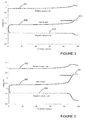
- FIGURE 3 illustrates the voltage behavior for a battery undergoing such a formation process, and includes a curve 310 representative of the overall battery voltage, a curve 312 representative of the positive electrode potential versus a lithium reference electrode, and a curve 314 representative of the negative electrode potential versus a lithium reference electrode.
- the overall battery voltage gradually increases to a 2.8 volt plateau 311 at the end of formation process, while the negative electrode potential versus a lithium reference electrode drops to a level of between approximately 1.3 and 1.4 volts toward the end of curve 314.
- the formation process described in the preceding paragraph may result in a relatively low irreversible capacity loss for the battery (e.g., between approximately 6 and 11 percent) during the formation process.
- This irreversible capacity loss results primarily from the passivation of the two electrodes, and occurs when otherwise cyclable lithium ions in the battery (i.e., lithium ions that shuttle between the positive and negative electrodes during charging and discharging) combine with an electrode active material.
- FIGURE 4 illustrates the voltage behavior for the battery when it is subjected to two deep discharge cycles where the battery is discharged to zero volts, and includes a curve 320 representative of the overall battery voltage, a curve 322 representative of the positive electrode potential versus a lithium reference electrode, and a curve 324 representative of the negative electrode potential versus a lithium reference electrode.
- the curves 322, 324 representing the potentials of the positive and negative electrodes converge toward and intersect at a point 326 referred to as the zero volt crossing potential for the battery.
- the zero voltage crossing potential for this battery occurs at a point where the positive electrode potential versus a lithium reference electrode is less than 2.0 volts (e.g., between approximately 1.6 and 1.8 volts).
- FIGURE 7 is a graph that includes a curve 330 representative of the discharge capacity of the battery as it undergoes repeated deep discharge cycles.
- the variations in the curves at cycles 50 and 100 are a result of two characterization cycles that were run during the test. These characterization cycles consist of (1) a slow rate cycle to determine trends in full charge/discharge capacity, (2) an application rate cycle to determine impact of repeated deep discharge on performance in normal application conditions. Other smaller variations (such as around cycle 170) are experimental artifacts.
- the inventors have determined through experimentation that one factor that contributes to the capacity fade is that the positive active material (in this case LiCoO 2 ) tends to relatively rapidly degrade when driven to a potential versus a lithium reference electrode that is less than 2.0 volts (e.g., approximately 1.6 volts). It should be noted that where different positive active materials are used, degradation of such materials may occur at a different level. As illustrated in FIGURE 4 , the potential of the positive electrode versus a lithium reference electrode, as represented by curve 322, drops to a level that is below 2.0 volts as the battery is discharged to a near-zero-volt charge state and the curves 322, 324 approach the zero volt crossing potential 326 for the battery.
- the positive active material in this case LiCoO 2
- the inventors have surprisingly discovered that the resistance to capacity fade for a negative-limited battery that utilizes a lithium titanate active material on the negative electrode can be significantly improved by using a formation process in which the charging voltage is greater than the normal fully charged voltage of the battery, with no associated increase in charging rate (e.g., the same C/10 charging rate may be used as described in the preceding example).
- a lithium-ion battery (LiCoO 2 positive active material, lithium titanate negative active material) having an intended operating voltage range from 2.8 volts (fully charged state) to 1.8 volts (cut-off voltage) is subjected to a formation process that utilizes a charging voltage of between approximately 3.4 volts and 3.8 volts at a C/10 charge rate, after which the battery voltage is held at this level for a period of between approximately 4 and 12 hours.
- FIGURE 5 illustrates the voltage behavior for a battery undergoing such a formation process, and includes a curve 340 representative of the overall battery voltage, a curve 342 representative of the positive electrode potential versus a lithium reference electrode, and a curve 344 representative of the negative electrode potential versus a lithium reference electrode.
- the battery voltage gradually increases to a 3.4 volt plateau 341 at the end of formation process.
- the higher charging voltage during the formation process results in a greater amount of irreversible capacity loss as compared to formation process using a lower charging voltage (e.g., 2.8 volts).
- the total irreversible capacity loss obtained using the higher-voltage formation process is expected to be between approximately 12 and 20 percent, depending on factors including, for example, the selected cut-off voltage and hold duration.
- the negative electrode potential versus a lithium reference electrode drops to a level below approximately 0.9 volts (e.g., between approximately 0.5 and 0.8 volts) as the battery reaches its fully charged state (i.e., the charge top-off voltage during normal use), while the positive electrode potential does not exhibit a large voltage increase. This is primarily due to the fact that the battery is negative-limited such that the capacity of the negative electrode is less than that of the positive electrode (i.e., the negative electrode depletes before the positive electrode, which results in a potential drop for the negative electrode).
- a reaction takes place in which the solvent component of the electrolyte (e.g., ethylene carbonate) reduces.
- the solvent component of the electrolyte e.g., ethylene carbonate
- a passive film e.g., lithium carbonate or lithium alkyl carbonate
- an additive such as carbon or a carbon-based material may be provided in the negative active material to assist in the formation of the passive film and to increase the amount of lithium that reacts irreversibly to form the film (e.g., between approximately 5 and 10 volume percent carbon may be provided in the lithium titanate material).
- One advantageous feature of the reduction reaction is that the increased irreversible capacity loss of the battery tends to increase the zero volt crossing potential for the battery, which allows for enhanced resistance to capacity fade since the higher zero volt crossing potential is above the level where the positive active material degrades.
- FIGURE 6 illustrates the voltage behavior for such a battery when it is subjected to two deep discharge cycles where the battery is discharged to zero volts, and includes a curve 350 representative of the overall battery voltage, a curve 352 representative of the positive electrode potential versus a lithium reference electrode, and a curve 354 representative of the negative electrode potential versus a lithium reference electrode.
- the curves 352, 354 representing the potentials of the positive and negative electrodes converge toward and intersect at the zero volt crossing potential 356 for the battery.
- the zero voltage crossing potential for this battery occurs at a point where the positive electrode potential versus a lithium reference electrode is greater than approximately 3.5 volts, which is above the threshold at which the positive active material (LiCoO 2 ) would be expected to degrade. It should also be noted that the lithium titanate negative electrode active material is also stable at this potential.
- the battery produced using the high-voltage formation process exhibits significantly enhanced resistance to capacity fade when subjected to repeated deep discharge cycles, as illustrated by the curve 360 in FIGURE 7 .
- the capacity of the battery is substantially constant over approximately 170 deep discharge cycles, in contrast to the relatively significant capacity fade exhibited by the battery using a more conventional formation process (curve 330).
- the use of a voltage that exceeds the voltage of the fully charged battery during the formation process acts to induce a larger amount of irreversible capacity loss in the battery than would otherwise be obtained. This in turn increases the zero voltage crossing potential for the battery above the level where the positive active material would degrade. As a result, the resistance to capacity fade with repeated deep discharge cycles is enhanced.
- Lithium ion cells having nominal capacities of approximately 0.15 ampere hours (Ah) were prepared having a lithium cobalt oxide (LiCoO 2 ) active material on the positive electrode and a lithium titanate active material on the negative electrode.
- the electrolyte used included a mixture of ethylene carbonate, ethylmethyl carbonate, and I molar LiPF 6 as the lithium salt.
- the cells were constructed as spirally wound prismatic cells hermetically sealed in a stainless steel can with a glass feedthrough.
- the negative and positive electrodes for the cells were prepared via a slurry coating and calendaring process. Both electrodes included the aforementioned active material, a conductive carbon additive, and organic binder. The mass loading (grams of materials per unit area) during the slurry coating process was controlled on both electrodes to attain a mass ratio of the two active materials to be 0.71. Based on the nominal specific capacities of the two active materials, determined via half cell testing (150 mAh/g for lithium cobalt oxide, 165 mAh/g for lithium titanate), the cell balance of this cell was 0.78 (i.e., the nominal capacity of the negative electrode was 78% of the nominal capacity of the positive electrode).
- Cells built with the above design were subjected to a conventional formation process in which the cells were charged at C/10 (15 mA) to the normal cut-off voltage of 2.8 volts and were held potentiostatically at 2.8 volts for 4 hours.
- Another group of cells built with the above design were subjected to an improved high voltage formation process. In this process, the cells were charged at C/10 (15 mA) to 3.4 volts and were held potentiostatically at 3.4 volts for 4 hours.
- both groups of cells were discharged at C/10 to 1.8 volts and held at 1.8 volts for 4 hours.
- the capacities delivered by the cells were measured both during the formation charge process and during the discharge process.
- the measured capacity values are given in Table 2.
- the formation charge capacity is typically greater than the discharge capacity, which is indicative of the irreversible capacity loss accounted for by the irreversible processes.
- the cells show 6.5% irreversible capacity during the conventional formation process, compared to 12.2% in the improved high voltage formation process.
- the difference in the irreversible capacities is approximately 5.7% between the 2.8 volts formation and high voltage 3.4 volts formation. This difference is seen to increase as a greater voltage, and/or a longer potentiostatic hold duration is chosen. It is noteworthy that this greater irreversible capacity docs not reduce the reversible capacity of the cell.
- Cycle 1 discharge capacity is the same for both groups of cells, as shown in Table 2.
- FIGURE 7 The difference in performance of the two groups of cells in this test is shown in FIGURE 7 , where the capacity obtained in every cycle as a percent of the initial capacity is plotted versus the cycle number.
- the cells with the conventional formation show large capacity fade, with the capacity falling to approximately 52% after 160 deep discharge cycles. In sharp contrast, the cells with the high voltage formation continue to show greater than 95% of the initial capacity after 160 deep discharge cycles.
- FIGURE 8 illustrates a schematic view of a system 400 (e.g., an implantable medical device) implanted within a body or torso 432 of a patient 430.
- the system 400 includes a device 410 in the form of an implantable medical device that for purposes of illustration is shown as a defibrillator configured to provide a therapeutic high voltage (e.g., 700 volt) treatment for the patient 430.
- a therapeutic high voltage e.g. 700 volt
- the device 410 includes a container or housing 414 that is hermetically sealed and biologically inert according to an exemplary embodiment.
- the container may be made of a conductive material.
- One or more leads 416 electrically connect the device 410 and to the patient's heart 420 via a vein 422.
- Electrodes 417 are provided to sense cardiac activity and/or provide an electrical potential to the heart 420.
- At least a portion of the leads 416 (e.g., an end portion of the leads shown as exposed electrodes 417) may be provided adjacent or in contact with one or more of a ventricle and an atrium of the heart 420.
- the device 410 includes a battery 440 provided therein to provide power for the device 410.
- the size and capacity of the battery 440 may be chosen based on a number of factors, including the amount of charge required for a given patient's physical or medical characteristics, the size or configuration of the device, and any of a variety of other factors.
- the battery is a 5 mAh battery.
- the battery is a 300 mAh battery.
- the battery may have a capacity of between approximately 1 and 1000 mAh.
- more than one battery may be provided to power the device 410.
- the batteries may have the same capacity or one or more of the batteries may have a higher or lower capacity than the other battery or batteries.
- one of the batteries may have a capacity of approximately 500 mAh while another of the batteries may have a capacity of approximately 75 mAh.
- the battery may be configured such that it may be charged and recharged using an inductive charging system in which a primary or external coil is provided at an exterior surface of a portion of the body (either proximate or some distance away from the battery) and a secondary or internal coil is provided below the skin adjacent the primary coil.
- a primary or external coil is provided at an exterior surface of a portion of the body (either proximate or some distance away from the battery) and a secondary or internal coil is provided below the skin adjacent the primary coil.
- an implantable neurological stimulation device 500 may include a battery 502 such as those described above with respect to the various exemplary embodiments. Examples of some neuro stimulation products and related components are shown and described in a brochure titled "Implantable Neurostimulation Systems” available from Medtronic, Inc.
- An INS generates one or more electrical stimulation signals that are used to influence the human nervous system or organs. Electrical contacts carried on the distal end of a lead are placed at the desired stimulation site such as the spine or brain and the proximal end of the lead is connected to the INS. The INS is then surgically implanted into an individual such as into a subcutaneous pocket in the abdomen, pectoral region, or upper buttocks area. A clinician programs the INS with a therapy using a programmer. The therapy configures parameters of the stimulation signal for the specific patient's therapy.
- An INS can be used to treat conditions such as pain, incontinence, movement disorders such as epilepsy and Parkinson's disease, and sleep apnea.
- Additional therapies appear promising to treat a variety of physiological, psychological, and emotional conditions.
- an external screener that replicates some or all of the INS functions is typically connected to the patient to evaluate the efficacy of the proposed therapy.
- the INS 500 includes a lead extension 522 and a stimulation lead 524.
- the stimulation lead 524 is one or more insulated electrical conductors with a connector 532 on the proximal end and electrical contacts (not shown) on the distal end.
- Some stimulation leads are designed to be inserted into a patient percutaneously, such as the Model 3487A Pisces-Quad ® lead available from Medtronic, Inc. of Minneapolis Minn., and stimulation some leads arc designed to be surgically implanted, such as the Model 3998 Specify ® lead also available from Medtronic.
- the lead connector 532 can be connected directly to the INS 500 (e.g., at a point 536), typically the lead connector 532 is connected to a lead extension 522.
- the lead extension 522 such as a Model 7495 available from Medtronic, is then connected to the INS 500.
- Implantation of an INS 500 typically begins with implantation of at least one stimulation lead 524, usually while the patient is under a local anesthetic.
- the stimulation lead 524 can either be percutaneously or surgically implanted. Once the stimulation lead 524 has been implanted and positioned, the stimulation lead's 524 distal end is typically anchored into position to minimize movement of the stimulation lead 524 after implantation.
- the stimulation lead's 524 proximal end can be configured to connect to a lead extension 522.
- the INS 500 is programmed with a therapy and the therapy is often modified to optimize the therapy for the patient (i.e., the INS may be programmed with a plurality of programs or therapies such that an appropriate therapy may be administered in a given situation).
- a physician programmer and a patient programmer may also be provided to allow a physician or a patient to control the administration of various therapies.
- a physician programmer also known as a console programmer, uses telemetry to communicate with the implanted INS 500, so a clinician can program and manage a patient's therapy stored in the INS 500, troubleshoot the patient's INS system, and/or collect data.
- An example of a physician programmer is a Model 7432 Console Programmer available from Medtronic.
- a patient programmer also uses telemetry to communicate with the INS 500, so the patient can manage some aspects of her therapy as defined by the clinician.
- An example of a patient programmer is a Model 7434 Itrel ® 3 EZ Patient Programmer available from Medtronic.
- a battery provided as part of the INS 500 may be configured such that it may be charged and recharged using an inductive charging system in which a primary or external coil is provided at an exterior surface of a portion of the body (either proximate or some distance away from the battery) and a secondary or internal coil is provided below the skin adjacent the primary coil.
- implantable medical devices are shown and described as a defibrillator and a neurological stimulation device, it should be appreciated that other types of implantable medical devices may be utilized according to other exemplary embodiments, such as pacemakers, cardioverters, cardiac contractility modules, drug administering devices, diagnostic recorders, cochlear implants, and the like for alleviating the adverse effects of various health ailments.
- the medical devices described herein may be charged or recharged when the medical device is implanted within a patient. That is, according to an exemplary embodiment, there is no need to disconnect or remove the medical device from the patient in order to charge or recharge the medical device.
Landscapes
- Chemical & Material Sciences (AREA)
- Electrochemistry (AREA)
- General Chemical & Material Sciences (AREA)
- Chemical Kinetics & Catalysis (AREA)
- Engineering & Computer Science (AREA)
- Manufacturing & Machinery (AREA)
- Inorganic Chemistry (AREA)
- Materials Engineering (AREA)
- Physics & Mathematics (AREA)
- Condensed Matter Physics & Semiconductors (AREA)
- General Physics & Mathematics (AREA)
- Battery Electrode And Active Subsutance (AREA)
- Secondary Cells (AREA)
Claims (15)
- Procédé pour produire une batterie, comportant de :fournir une batterie comportant une électrode positive, une électrode négative, et un électrolyte comportant un solvant et un sel, dans lequel l'électrode positive comporte au moins un matériau actif choisi parmi le groupe constitué de LiCoO2, LiMn2O4, LiCoxNi(1-x)O2 (où x est compris entre 0,5 et 0,8), LiNixCoyMn(1-x-y)O2, LiMxCoyNi(1-x-y)O2 (où M est de l'aluminium ou du titane et x est compris entre 0,5 et 0,3 et y est compris entre 0,1 et 0,3), dans lequel la capacité de l'électrode négative est inférieure à celle de l'électrode positive, et dans lequel l'électrode négative comporte un matériau actif ayant un potentiel moyen par rapport à une électrode de référence au lithium supérieur à approximativement 0,2 volts ; et caractérisé parl'application d'une charge initiale à la batterie à une tension qui est supérieure à une tension entièrement chargée de la batterie pendant une durée suffisante pour amener au moins une partie du solvant à subir une réaction de réduction, dans lequel l'étape d'application d'une charge initiale à la batterie agit pour augmenter la perte de capacité irréversible de la batterie pendant la charge initiale et permet à la batterie d'avoir une tolérance améliorée jusqu'à des conditions de décharge profonde.
- Procédé selon la revendication 1, dans lequel l'étape d'application d'une charge initiale à la batterie est exécutée pendant une durée suffisante pour amener le potentiel de l'électrode négative par rapport à une électrode de référence au lithium à chuter à un niveau tel qu'une réaction irréversible survient entre l'électrolyte et l'électrode négative.
- Procédé selon la revendication 1, dans lequel la tension entièrement chargée de la batterie est comprise entre approximativement 2,5 et 3,0 volts et l'étape consistant à appliquer une charge initiale à la batterie utilise une tension comprise entre 3,4 et 3,8 volts.
- Procédé selon la revendication 3, dans lequel l'électrode positive comporte un matériau actif et l'étape consistant à appliquer une charge initiale à la batterie augmente le potentiel de passage par zéro volt de la batterie jusqu'à un niveau qui est supérieur à un potentiel de décomposition du matériau actif de l'électrode positive.
- Procédé selon la revendication 4, dans lequel le potentiel de passage par zéro volt de la batterie après l'étape consistant à appliquer la charge initiale à la batterie est supérieur à 3,0 volts par rapport à Li/li+.
- Procédé selon la revendication 3, dans lequel l'étape consistant à appliquer une charge initiale à la batterie est exécutée pendant une durée suffisante pour amener le potentiel de l'électrode négative par rapport à une électrode de référence au lithium à chuter jusqu'à un niveau situé au-dessous de 0,9 volts.
- Procédé selon la revendication 1, dans lequel pendant l'étape consistant à appliquer la charge initiale à la batterie, la tension de l'électrode positive par rapport à une électrode de référence au lithium n'atteint pas un niveau suffisant pour engendrer l'oxydation de l'électrolyte au niveau de l'électrode positive.
- Procédé selon la revendication 1, dans lequel l'étape consistant à appliquer une charge initiale à la batterie survient à une vitesse de chargement de C/10 ou plus lente.
- Procédé selon la revendication 1, dans lequel l'électrode négative comporte un additif configuré pour améliorer la formation d'une couche SEI.
- Procédé selon la revendication 9, dans lequel l'additif comporte du carbone.
- Procédé selon la revendication 1, dans lequel l'électrolyte comporte du carbonate d'éthylène.
- Procédé selon la revendication 1, dans lequel le matériau actif de l'électrode négative comporte un matériau en titanate de lithium.
- Procédé selon la revendication 1, dans lequel la réaction dans laquelle une partie du solvant se réduit agit pour former un film sur l'électrode négative.
- Procédé selon la revendication 1, dans lequel le matériau actif pour l'électrode négative comporte L14T15O12.
- Procédé selon la revendication 1, dans lequel le matériau actif de l'électrode positive est sélectionné parmi LiCoO2 et LiMn2O4.
Applications Claiming Priority (2)
| Application Number | Priority Date | Filing Date | Title |
|---|---|---|---|
| US12/112,979 US8980453B2 (en) | 2008-04-30 | 2008-04-30 | Formation process for lithium-ion batteries |
| PCT/US2008/082598 WO2009134283A1 (fr) | 2008-04-30 | 2008-11-06 | Procédé de fabrication de batteries lithium-ion |
Publications (2)
| Publication Number | Publication Date |
|---|---|
| EP2294650A1 EP2294650A1 (fr) | 2011-03-16 |
| EP2294650B1 true EP2294650B1 (fr) | 2012-10-03 |
Family
ID=40291158
Family Applications (1)
| Application Number | Title | Priority Date | Filing Date |
|---|---|---|---|
| EP08874144A Not-in-force EP2294650B1 (fr) | 2008-04-30 | 2008-11-06 | Procédé de fabrication de batteries lithium-ion |
Country Status (3)
| Country | Link |
|---|---|
| US (3) | US8980453B2 (fr) |
| EP (1) | EP2294650B1 (fr) |
| WO (1) | WO2009134283A1 (fr) |
Cited By (1)
| Publication number | Priority date | Publication date | Assignee | Title |
|---|---|---|---|---|
| CN106532158A (zh) * | 2015-09-14 | 2017-03-22 | 丰田自动车株式会社 | 全固体电池系统及其制造方法 |
Families Citing this family (48)
| Publication number | Priority date | Publication date | Assignee | Title |
|---|---|---|---|---|
| US7927742B2 (en) | 2004-10-29 | 2011-04-19 | Medtronic, Inc. | Negative-limited lithium-ion battery |
| US7641992B2 (en) | 2004-10-29 | 2010-01-05 | Medtronic, Inc. | Medical device having lithium-ion battery |
| US7563541B2 (en) | 2004-10-29 | 2009-07-21 | Medtronic, Inc. | Lithium-ion battery |
| US8980453B2 (en) | 2008-04-30 | 2015-03-17 | Medtronic, Inc. | Formation process for lithium-ion batteries |
| US7582387B2 (en) | 2004-10-29 | 2009-09-01 | Medtronic, Inc. | Lithium-ion battery |
| US7662509B2 (en) | 2004-10-29 | 2010-02-16 | Medtronic, Inc. | Lithium-ion battery |
| US9077022B2 (en) | 2004-10-29 | 2015-07-07 | Medtronic, Inc. | Lithium-ion battery |
| CN101048898B (zh) | 2004-10-29 | 2012-02-01 | 麦德托尼克公司 | 锂离子电池及医疗装置 |
| US8168330B2 (en) * | 2006-04-11 | 2012-05-01 | Enerdel, Inc. | Lithium titanate cell with reduced gassing |
| JP5288816B2 (ja) * | 2008-01-31 | 2013-09-11 | 株式会社オハラ | 固体電池 |
| JP5396798B2 (ja) * | 2008-09-30 | 2014-01-22 | Tdk株式会社 | 活物質材料、それを用いた正極及びリチウムイオン二次電池 |
| US8821763B2 (en) * | 2008-09-30 | 2014-09-02 | Tdk Corporation | Active material and method of manufacturing active material |
| US20100233545A1 (en) * | 2009-03-16 | 2010-09-16 | Tdk Corporation | Active material, method of manufacturing active material, electrode, and lithium-ion secondary battery |
| US20110052995A1 (en) * | 2009-08-28 | 2011-03-03 | Tdk Corporation | Active material, electrode containing the same, lithium secondary battery provided therewith and method for manufacture of the active material |
| US8594806B2 (en) | 2010-04-30 | 2013-11-26 | Cyberonics, Inc. | Recharging and communication lead for an implantable device |
| US9287580B2 (en) | 2011-07-27 | 2016-03-15 | Medtronic, Inc. | Battery with auxiliary electrode |
| US20130149560A1 (en) | 2011-12-09 | 2013-06-13 | Medtronic, Inc. | Auxiliary electrode for lithium-ion battery |
| CN103427125B (zh) * | 2012-05-15 | 2016-04-13 | 清华大学 | 硫基聚合物锂离子电池的循环方法 |
| US9343923B2 (en) | 2012-08-23 | 2016-05-17 | Cyberonics, Inc. | Implantable medical device with backscatter signal based communication |
| US9935498B2 (en) | 2012-09-25 | 2018-04-03 | Cyberonics, Inc. | Communication efficiency with an implantable medical device using a circulator and a backscatter signal |
| US9209494B2 (en) | 2012-09-28 | 2015-12-08 | Palo Alto Research Center Incorporated | Monitoring/managing electrochemical energy device using detected intercalation stage changes |
| US9203122B2 (en) | 2012-09-28 | 2015-12-01 | Palo Alto Research Center Incorporated | Monitoring and management for energy storage devices |
| US9005311B2 (en) | 2012-11-02 | 2015-04-14 | Sion Power Corporation | Electrode active surface pretreatment |
| TWI613850B (zh) * | 2013-05-22 | 2018-02-01 | 石原產業股份有限公司 | 非水電解質二次電池之製造方法 |
| CN103354285A (zh) * | 2013-06-21 | 2013-10-16 | 合肥恒能新能源科技有限公司 | 一种用于大容量磷酸铁锂的化成激活工艺 |
| US9812732B2 (en) * | 2013-08-16 | 2017-11-07 | Johnson Controls Technology Company | Dual storage system and method with lithium ion and lead acid battery cells |
| US9276293B2 (en) * | 2013-08-30 | 2016-03-01 | Southwestern Research Institute | Dynamic formation protocol for lithium-ion battery |
| US9553465B2 (en) | 2014-04-21 | 2017-01-24 | Palo Alto Research Center Incorporated | Battery management based on internal optical sensing |
| EP2945211B1 (fr) * | 2014-05-15 | 2018-11-21 | Saft Groupe S.A. | Oxyde de titanate de lithium comme électrode négative dans des cellules lithium-ion |
| US9677916B2 (en) | 2014-07-15 | 2017-06-13 | Palo Alto Research Center Incorporated | Energy system monitoring |
| US10403922B2 (en) | 2014-07-23 | 2019-09-03 | Palo Alto Research Center Incorporated | Battery with embedded fiber optic cable |
| US10446886B2 (en) | 2014-07-23 | 2019-10-15 | Palo Alto Research Center Incorporated | Embedded fiber optic cables for battery management |
| JP6970617B2 (ja) * | 2015-03-02 | 2021-11-24 | イーオーセル リミテッド | ケイ素:ケイ酸リチウムの複合材母材中にナノケイ素粒子を埋込んだケイ素−酸化ケイ素−リチウムの複合材料、及びその製造工程、及びバッテリ二次セル負電極製造工程でのその使用、及びリチウムイオンバッテリセル |
| GB2543830A (en) | 2015-10-30 | 2017-05-03 | Sharp Kk | Formation method for sodium ion cell or battery |
| CN106785052B (zh) * | 2015-11-23 | 2020-07-17 | 天津荣盛盟固利新能源科技有限公司 | 一种钛酸锂电池的化成方法 |
| CN109314269B (zh) * | 2016-06-15 | 2021-10-29 | 罗伯特·博世有限公司 | 锂离子电池及其制备方法 |
| SG11201901880SA (en) * | 2016-09-02 | 2019-03-28 | Eocell Ltd | Volume change compensated silicon-silicon oxide-lithium composite material having nano silicon particles embedded in a silicon: silicon lithium silicate composite matrix, and cyclical ex-situ manufacturing processes |
| DE102016220998A1 (de) | 2016-10-25 | 2018-04-26 | Volkswagen Aktiengesellschaft | Verfahren zum Herstellen einer Lithium-Ionen-Zelle und einer Lithium-Ionen-Batterie, Lithium-Ionen-Batterie |
| US10317256B2 (en) | 2017-04-14 | 2019-06-11 | Palo Alto Research Center Incorporated | Monitoring transportation systems |
| US11251430B2 (en) | 2018-03-05 | 2022-02-15 | The Research Foundation For The State University Of New York | ϵ-VOPO4 cathode for lithium ion batteries |
| KR102364480B1 (ko) | 2018-05-15 | 2022-02-18 | 주식회사 엘지에너지솔루션 | 음극 활물질, 상기 음극 활물질을 포함하는 음극, 및 상기 음극을 포함하는 리튬 이차 전지 |
| CN111540951A (zh) * | 2020-05-12 | 2020-08-14 | 上海纳米技术及应用国家工程研究中心有限公司 | 一种用于钛酸锂负极材料的锂离子电池高压电解液 |
| CN112151871A (zh) * | 2020-09-28 | 2020-12-29 | 苏州酷卡环保科技有限公司 | 一种高温锂离子电池的化成方法 |
| CN112201854A (zh) * | 2020-11-11 | 2021-01-08 | 江苏卫健信息科技有限公司 | 一种动力锂离子电池的化成方法 |
| CN112599874B (zh) * | 2020-12-09 | 2022-06-14 | 中国科学院上海硅酸盐研究所 | 一种提高准固态锂离子电池性能的电化学预处理方法 |
| CN113054270B (zh) * | 2021-03-24 | 2022-11-08 | 骆驼集团新能源电池有限公司 | 一种软包锂离子电池化成工艺 |
| CN115642324B (zh) * | 2021-07-19 | 2024-09-10 | 比亚迪股份有限公司 | 一种锂电池及其制备方法 |
| CN119481329A (zh) * | 2024-11-13 | 2025-02-18 | 孝感楚能新能源创新科技有限公司 | 一种基于双电芯的锂离子电池及其制备方法 |
Family Cites Families (220)
| Publication number | Priority date | Publication date | Assignee | Title |
|---|---|---|---|---|
| US3308306A (en) * | 1964-05-08 | 1967-03-07 | Specialties Dev Corp | Electrical power supply and battery charges |
| DE1571997B2 (de) | 1966-10-28 | 1975-07-10 | Robert Bosch Gmbh, 7000 Stuttgart | Gasdichter elektrischer Akkumulator mit Ladekontrollelektrode und Verfahren zur Herstellung der Ladekontrollelektrode |
| US3904434A (en) | 1971-11-17 | 1975-09-09 | Matsushita Electric Industrial Co Ltd | Sealed lead storage battery |
| US3791867A (en) | 1972-07-24 | 1974-02-12 | Bell Telephone Labor Inc | Rechargable nonaqueous battery |
| US3864167A (en) | 1973-04-19 | 1975-02-04 | Bell Telephone Labor Inc | Non-aqueous battery using chalcogenide electrode |
| US3898096A (en) | 1973-06-11 | 1975-08-05 | Rockwell International Corp | Lithium-molten salt cell with transition metal chalcogenide positive electrode |
| US4048397A (en) | 1975-01-17 | 1977-09-13 | Maxs Ag | Method and apparatus for interconnecting stacked electrodes of batteries |
| US4009052A (en) | 1975-02-24 | 1977-02-22 | Exxon Research And Engineering Company | Chalcogenide battery |
| IL50024A (en) | 1976-07-12 | 1979-05-31 | Israel State | Secondary cells |
| US4049887A (en) | 1976-07-20 | 1977-09-20 | Exxon Research & Engineering Co. | Electrochemical cells with cathode-active materials of layered compounds |
| US4077151A (en) * | 1976-11-18 | 1978-03-07 | Johnson Lloyd M | Non-snagging sinker |
| US4194062A (en) | 1978-07-27 | 1980-03-18 | Bell Telephone Laboratories, Incorporated | Rechargeable dichalcogenide cell |
| US4202702A (en) | 1978-12-26 | 1980-05-13 | Ferro Corporation | Inorganic pigment comprising a solid solution of differing spinels |
| JPS56136462A (en) | 1980-03-27 | 1981-10-24 | Yuasa Battery Co Ltd | Secondary battery |
| IT1131478B (it) | 1980-05-13 | 1986-06-25 | Consiglio Nazionale Ricerche | Pile ricaricabili ad elevata energia specifica con anodo e catodo a intercalazione |
| JPS5711476A (en) | 1980-06-24 | 1982-01-21 | Yuasa Battery Co Ltd | Secondary organic electrolyte battery |
| US4340652A (en) | 1980-07-30 | 1982-07-20 | The United States Of America As Represented By The United States Department Of Energy | Ternary compound electrode for lithium cells |
| JPS57152669A (en) | 1981-03-18 | 1982-09-21 | Sanyo Electric Co Ltd | Chargeable organic electrolyte battery |
| US4446212A (en) | 1981-07-29 | 1984-05-01 | The United States Of America As Represented By The United States Department Of Energy | Electrochemical cell |
| US4507371A (en) | 1982-06-02 | 1985-03-26 | South African Inventions Development Corporation | Solid state cell wherein an anode, solid electrolyte and cathode each comprise a cubic-close-packed framework structure |
| US4581122A (en) | 1982-06-09 | 1986-04-08 | Energy Development Associates, Inc. | State of charge analytical apparatus |
| DE3230410A1 (de) | 1982-08-16 | 1984-02-16 | Varta Batterie Ag, 3000 Hannover | Stuetz- und ableitergerueste mit intermetallischen haftvermittlern fuer lithium enthaltende batterieelektroden |
| JPS59217964A (ja) | 1983-05-26 | 1984-12-08 | Hitachi Ltd | 薄膜電池の正極構造 |
| DE3680249D1 (de) | 1985-05-10 | 1991-08-22 | Asahi Chemical Ind | Sekundaerbatterie. |
| US4764437A (en) | 1986-05-29 | 1988-08-16 | The United States Of America As Represented By The Department Of Energy | Lithium disulfide battery |
| JPS631708A (ja) | 1986-06-23 | 1988-01-06 | Yutaka Giken:Kk | 触媒コンバ−タ用気密緩衝体 |
| US4830939B1 (en) | 1987-10-30 | 1996-10-08 | Mhb Joint Venture | Radiation cured solid electrolytes and electrochemical devices employing the same |
| EP0354966B1 (fr) | 1988-01-22 | 1996-06-12 | Japan Storage Battery Company Limited | Batterie d'accumulateurs alcalins et procede de production |
| USH723H (en) | 1988-07-06 | 1990-01-02 | The United States Of America As Represented By The Secretary Of The Army | Lithium electrochemical cell containing diethylcarbonate as an electrolyte solvent additive |
| US5196379A (en) * | 1988-09-19 | 1993-03-23 | Regents Of The University Of Minneapolis | Method of depositing oxide passivation layers on high temperature superconductors |
| JP2797390B2 (ja) | 1989-04-03 | 1998-09-17 | ソニー株式会社 | 非水電解質二次電池 |
| JPH02309568A (ja) | 1989-05-24 | 1990-12-25 | Brother Ind Ltd | リチウム二次電池 |
| JP3019326B2 (ja) | 1989-06-30 | 2000-03-13 | 松下電器産業株式会社 | リチウム二次電池 |
| US5162170A (en) | 1989-07-21 | 1992-11-10 | Mistubishi Petrochemical Co., Ltd. | Electrode for secondary battery |
| JP2856795B2 (ja) | 1989-12-05 | 1999-02-10 | 三菱化学株式会社 | 二次電池用電極 |
| GB2242898B (en) | 1990-04-12 | 1993-12-01 | Technology Finance Corp | Lithium transition metal oxide |
| CA2043472A1 (fr) | 1990-06-04 | 1991-12-05 | Mitsutaka Miyabayashi | Electrode pour batterie secondaire |
| US5264201A (en) | 1990-07-23 | 1993-11-23 | Her Majesty The Queen In Right Of The Province Of British Columbia | Lithiated nickel dioxide and secondary cells prepared therefrom |
| US5284721A (en) | 1990-08-01 | 1994-02-08 | Alliant Techsystems Inc. | High energy electrochemical cell employing solid-state anode |
| US5147739A (en) | 1990-08-01 | 1992-09-15 | Honeywell Inc. | High energy electrochemical cell having composite solid-state anode |
| DE4025208A1 (de) | 1990-08-09 | 1992-02-13 | Varta Batterie | Elektrochemisches sekundaerelement |
| US5196279A (en) | 1991-01-28 | 1993-03-23 | Bell Communications Research, Inc. | Rechargeable battery including a Li1+x Mn2 O4 cathode and a carbon anode |
| US5340666A (en) | 1991-03-11 | 1994-08-23 | Battery Technologies Inc. | Rechargeable alkaline manganese cell having improved capacity and improved energy density |
| US5147737A (en) | 1991-05-07 | 1992-09-15 | Wilson Greatbatch Ltd. | Electrochemical cell with improved efficiency serpentine electrode |
| JP3335366B2 (ja) | 1991-06-20 | 2002-10-15 | 三菱化学株式会社 | 二次電池用電極 |
| JPH05166538A (ja) | 1991-12-16 | 1993-07-02 | Matsushita Electric Ind Co Ltd | 非水電解液二次電池 |
| US5478671A (en) | 1992-04-24 | 1995-12-26 | Fuji Photo Film Co., Ltd. | Nonaqueous secondary battery |
| US5470678A (en) | 1992-08-19 | 1995-11-28 | Hitachi Maxell, Ltd. | Lithium cell with a cathode comprising a copper compound oxide |
| US5300373A (en) | 1992-09-11 | 1994-04-05 | Valence Technology, Inc. | Electrochemical cell stack and method of making an electrochemical cell stack |
| US5322746A (en) | 1992-10-02 | 1994-06-21 | Her Majesty The Queen In Right Of The Province Of British Columbia As Represented By The Minister Of Finance & Corporate Relations | Electrode composition and design for high energy density cells |
| US5510212A (en) | 1993-01-13 | 1996-04-23 | Delnick; Frank M. | Structural micro-porous carbon anode for rechargeable lithium ion batteries |
| US5418090A (en) | 1993-02-17 | 1995-05-23 | Valence Technology, Inc. | Electrodes for rechargeable lithium batteries |
| US5296318A (en) | 1993-03-05 | 1994-03-22 | Bell Communications Research, Inc. | Rechargeable lithium intercalation battery with hybrid polymeric electrolyte |
| US5587253A (en) | 1993-03-05 | 1996-12-24 | Bell Communications Research, Inc. | Low resistance rechargeable lithium-ion battery |
| JP3502118B2 (ja) | 1993-03-17 | 2004-03-02 | 松下電器産業株式会社 | リチウム二次電池およびその負極の製造法 |
| JP3384027B2 (ja) | 1993-05-14 | 2003-03-10 | ソニー株式会社 | 充電方法および充電器 |
| US5331268A (en) * | 1993-08-02 | 1994-07-19 | Motorola, Inc. | Method and apparatus for dynamically charging a battery |
| US5411537A (en) | 1993-10-29 | 1995-05-02 | Intermedics, Inc. | Rechargeable biomedical battery powered devices with recharging and control system therefor |
| US6893772B2 (en) | 1993-11-19 | 2005-05-17 | Medtronic, Inc. | Current collector for lithium electrode |
| US5478668A (en) | 1993-11-30 | 1995-12-26 | Bell Communications Research Inc. | Rechargeable lithium battery construction |
| US5525441A (en) | 1994-09-13 | 1996-06-11 | Power Conversion, Inc. | Folded electrode configuration for galvanic cells |
| US5498489A (en) | 1995-04-14 | 1996-03-12 | Dasgupta; Sankar | Rechargeable non-aqueous lithium battery having stacked electrochemical cells |
| WO1996027910A1 (fr) | 1995-03-06 | 1996-09-12 | Fuji Photo Film Co., Ltd. | Element d'accumulateur non aqueux |
| US5569553A (en) | 1995-03-08 | 1996-10-29 | Wilson Greatbatch Ltd. | Battery design for achieving end-of-life indication during electrical discharge |
| JP3387724B2 (ja) | 1995-03-17 | 2003-03-17 | キヤノン株式会社 | 二次電池用電極、その製造方法及び該電極を有する二次電池 |
| CA2147578C (fr) | 1995-04-21 | 2002-04-16 | Jan Naess Reimers | Oxyde de lithium et de manganise et son utilisation dans les piles rechargeables |
| US5888665A (en) | 1995-06-07 | 1999-03-30 | California Institute Of Technology | LaNi5 is-based metal hydride electrode in Ni-MH rechargeable cells |
| DE19528049A1 (de) | 1995-07-31 | 1997-02-06 | Varta Batterie | Lithium-Ionen-Zelle |
| US5652072A (en) | 1995-09-21 | 1997-07-29 | Minnesota Mining And Manufacturing Company | Battery containing bis(perfluoroalkylsulfonyl)imide and cyclic perfluoroalkylene disulfonylimide salts |
| US5691081A (en) | 1995-09-21 | 1997-11-25 | Minnesota Mining And Manufacturing Company | Battery containing bis(perfluoroalkylsulfonyl)imide and cyclic perfluoroalkylene disulfonylimide salts |
| US5851696A (en) | 1996-01-29 | 1998-12-22 | Valence Technology, Inc. | Rechargeable lithium battery |
| US5670862A (en) | 1996-03-12 | 1997-09-23 | Siliconix Incorporated | Rapid charging technique for lithium ion batteries |
| US5744264A (en) | 1996-06-13 | 1998-04-28 | Valence Technology, Inc. | Lithium ion electrochemical cell |
| KR100444804B1 (ko) | 1996-06-14 | 2004-10-14 | 히다치 마쿠세루가부시키가이샤 | 리튬 2차전지 |
| JPH1027626A (ja) | 1996-07-09 | 1998-01-27 | Matsushita Electric Ind Co Ltd | リチウム二次電池 |
| JP3269396B2 (ja) | 1996-08-27 | 2002-03-25 | 松下電器産業株式会社 | 非水電解質リチウム二次電池 |
| US6022640A (en) | 1996-09-13 | 2000-02-08 | Matsushita Electric Industrial Co., Ltd. | Solid state rechargeable lithium battery, stacking battery, and charging method of the same |
| US6203946B1 (en) | 1998-12-03 | 2001-03-20 | Valence Technology, Inc. | Lithium-containing phosphates, method of preparation, and uses thereof |
| DE69722890T2 (de) | 1996-10-28 | 2004-05-13 | Daiso Co., Ltd. | Polyethercopolymer und fester Polymerelektrolyt |
| US5783333A (en) | 1996-11-27 | 1998-07-21 | Polystor Corporation | Lithium nickel cobalt oxides for positive electrodes |
| US5744258A (en) | 1996-12-23 | 1998-04-28 | Motorola,Inc. | High power, high energy, hybrid electrode and electrical energy storage device made therefrom |
| JPH10188992A (ja) | 1996-12-24 | 1998-07-21 | Sony Corp | 非水電解液電池 |
| CA2196493C (fr) | 1997-01-31 | 2002-07-16 | Huanyu Mao | Additifs ameliorant le cycle de vie des batteries au lithium rechargeables a electrolyte non aqueux |
| JPH10312826A (ja) | 1997-03-10 | 1998-11-24 | Sanyo Electric Co Ltd | 非水電解質電池及びその充電方法 |
| DE69825797T2 (de) | 1997-03-13 | 2005-09-01 | Matsushita Electric Industrial Co., Ltd., Kadoma | Lithium-Ionen-Batterie |
| JP3363910B2 (ja) | 1997-03-19 | 2003-01-08 | 旭化成株式会社 | 非水系薄型電池 |
| FR2761201B1 (fr) | 1997-03-24 | 1999-05-07 | Alsthom Cge Alcatel | Generateur a boitier isole protege contre la corrosion |
| US5935724A (en) | 1997-04-04 | 1999-08-10 | Wilson Greatbatch Ltd. | Electrochemical cell having multiplate electrodes with differing discharge rate regions |
| US5935728A (en) | 1997-04-04 | 1999-08-10 | Wilson Greatbatch Ltd. | Electrochemical cell having multiplate and jellyroll electrodes with differing discharge rate regions |
| US6824920B1 (en) | 1997-06-03 | 2004-11-30 | Matsushita Electric Industrial Co., Ltd. | Non-aqueous electrolyte secondary battery comprising composite particles |
| US5776628A (en) | 1997-06-30 | 1998-07-07 | Wilson Greatbatch Ltd. | Flat-folded, multi-plate electrode assembly |
| US5911947A (en) | 1997-06-30 | 1999-06-15 | Compaq Computer Corporation | Fan-folded polymer-electrolyte cell |
| DE69842254D1 (de) | 1997-07-15 | 2011-06-16 | Ishihara Sangyo Kaisha | Lithiumwasserstofftitanat und verfahren zu dessen herstellung |
| ATE277672T1 (de) | 1997-08-01 | 2004-10-15 | Mann Alfred E Found Scient Res | Implantierbare einrichtung mit verbesserter anordnung zur ladung der batterie und zur energiezufuhr |
| US6599664B2 (en) | 1997-08-22 | 2003-07-29 | Yardney Technical Products, Inc. | Inorganic gel-polymer electrolyte |
| US6951576B1 (en) | 1997-10-21 | 2005-10-04 | Wilson Greatbatch Ltd. | Wound element electrode assembly design for use in prismatic case electrochemical cells |
| DK1036192T3 (da) | 1997-12-05 | 2003-06-10 | Upjohn Co | Fluorescensbaserede screeningsanalyser med høj hastighedforproteinkinaser og phosphataser |
| US6022643A (en) | 1997-12-08 | 2000-02-08 | Brookhaven Science Associates | Boron compounds as anion binding agents for nonaqueous battery electrolytes |
| US6352798B1 (en) | 1997-12-08 | 2002-03-05 | Brookhaven Science Associates, Llc | Phenyl boron-based compounds as anion receptors for non-aqueous battery electrolytes |
| US6171729B1 (en) | 1998-01-02 | 2001-01-09 | Wilson Greatbatch Ltd | Control of swelling in alkali metal electrochemical cells |
| CA2283670C (fr) | 1998-02-03 | 2011-06-07 | Acep Inc. | Materiaux utiles en tant que solutes electrolytiques |
| US6265100B1 (en) | 1998-02-23 | 2001-07-24 | Research International, Inc. | Rechargeable battery |
| CN1256801A (zh) | 1998-03-17 | 2000-06-14 | 三菱电机株式会社 | 锂离子电池及其形成方法 |
| IL124007A (en) | 1998-04-08 | 2001-08-26 | Univ Ramot | Long cycle-life alkali metal battery |
| JPH11297359A (ja) | 1998-04-15 | 1999-10-29 | Matsushita Electric Ind Co Ltd | 全固体リチウム二次電池 |
| JPH11307102A (ja) | 1998-04-24 | 1999-11-05 | Hitachi Ltd | リチウム二次電池とその製造法 |
| US6528208B1 (en) | 1998-07-09 | 2003-03-04 | The University Of Chicago | Anodes for rechargeable lithium batteries |
| US6221531B1 (en) | 1998-07-09 | 2001-04-24 | The University Of Chicago | Lithium-titanium-oxide anodes for lithium batteries |
| KR100443250B1 (ko) | 1998-09-24 | 2004-08-04 | 토마스 앤드 베츠 인터내셔널, 인코포레이티드 | 전기화학전지의 개량된 제조방법 |
| DE19845668A1 (de) | 1998-10-05 | 2000-04-06 | Varta Batterie | Sekundäre Lithium-Ionen-Zelle |
| JP4196234B2 (ja) | 1998-11-20 | 2008-12-17 | 株式会社ジーエス・ユアサコーポレーション | 非水電解質リチウム二次電池 |
| EP1014465A1 (fr) | 1998-12-16 | 2000-06-28 | Hughes Electronics Corporation | Pile aux ions lithium comprenant une feuille gravée comme collecteur de courant |
| US6489062B1 (en) | 1998-12-24 | 2002-12-03 | Seiko Instruments Inc. | Non-aqueous electrolyte secondary battery having heat-resistant electrodes |
| JP2000195499A (ja) | 1998-12-25 | 2000-07-14 | Kyocera Corp | リチウム電池 |
| JP4540167B2 (ja) | 1999-02-16 | 2010-09-08 | 東邦チタニウム株式会社 | チタン酸リチウムの製造方法 |
| US6645673B2 (en) | 1999-02-16 | 2003-11-11 | Toho Titanium Co., Ltd. | Process for producing lithium titanate and lithium ion battery and negative electrode therein |
| JP3625680B2 (ja) | 1999-03-25 | 2005-03-02 | 三洋電機株式会社 | リチウム二次電池 |
| US6228536B1 (en) | 1999-07-13 | 2001-05-08 | Hughes Electronics Corporation | Lithium-ion battery cell having an oxidized/reduced negative current collector |
| US6761744B1 (en) | 1999-07-16 | 2004-07-13 | Quallion Llc | Lithium thin film lamination technology on electrode to increase battery capacity |
| US6553263B1 (en) | 1999-07-30 | 2003-04-22 | Advanced Bionics Corporation | Implantable pulse generators using rechargeable zero-volt technology lithium-ion batteries |
| US6645675B1 (en) | 1999-09-02 | 2003-11-11 | Lithium Power Technologies, Inc. | Solid polymer electrolytes |
| JP3558007B2 (ja) | 1999-09-30 | 2004-08-25 | 宇部興産株式会社 | 非水電解液およびそれを用いたリチウム二次電池 |
| US6451480B1 (en) | 1999-10-18 | 2002-09-17 | Scott D. Gustafson | Polyimide-based lithium ion battery |
| JP2001126756A (ja) | 1999-10-25 | 2001-05-11 | Kyocera Corp | リチウム固体電解質電池およびその製造方法 |
| DE19952335B4 (de) | 1999-10-29 | 2007-03-29 | Fraunhofer-Gesellschaft zur Förderung der angewandten Forschung e.V. | In elektrochemischen Bauelementen verwendbare pastöse Masse, damit gebildete Schichten, Folien, Schichtverbünde und wiederaufladbare elektrochemische Zellen sowie Verfahren zur Herstellung der Schichten, Folien und Schichtverbünde |
| JP4623786B2 (ja) | 1999-11-10 | 2011-02-02 | 住友電気工業株式会社 | 非水二次電池 |
| US6461751B1 (en) | 1999-12-06 | 2002-10-08 | Ballard Power Systems Inc. | Method and apparatus for operating a fuel cell |
| JP2001185141A (ja) | 1999-12-22 | 2001-07-06 | Kyocera Corp | リチウム電池 |
| US6641953B2 (en) | 2000-01-12 | 2003-11-04 | Wilson Greatbatch Ltd. | Secondary cell with high rate pulse capability |
| EP2418713A1 (fr) | 2000-03-31 | 2012-02-15 | Sony Corporation | Séparateur, électrolyte gélifié, électrolyte non aqueux, électrode et cellule à électrolyte non aqueux les utilisant |
| US6596439B1 (en) | 2000-04-26 | 2003-07-22 | Quallion Llc | Lithium ion battery capable of being discharged to zero volts |
| US6777132B2 (en) | 2000-04-27 | 2004-08-17 | Valence Technology, Inc. | Alkali/transition metal halo—and hydroxy-phosphates and related electrode active materials |
| US6453198B1 (en) | 2000-04-28 | 2002-09-17 | Medtronic, Inc. | Power management for an implantable medical device |
| CN1428012A (zh) | 2000-05-12 | 2003-07-02 | 株式会社汤浅 | 非水电解质锂二次电池 |
| US6645670B2 (en) | 2000-05-16 | 2003-11-11 | Wilson Greatbatch Ltd. | Efficient cell stack for cells with double current collectors sandwich cathodes |
| EP1327280A2 (fr) | 2000-07-24 | 2003-07-16 | Shell Internationale Researchmaatschappij B.V. | Element electrochimique et processus de production de cet element |
| US7189475B2 (en) | 2000-07-27 | 2007-03-13 | Kabushiki Kaisha Toyota Chuo Kenkyusho | Lithium secondary battery |
| GB0018635D0 (en) | 2000-07-31 | 2000-09-13 | Aea Technology Plc | Polymer electrolyte |
| TW508861B (en) | 2000-08-08 | 2002-11-01 | Matsushita Electric Industrial Co Ltd | Non-aqueous electrolyte secondary battery and positive electrode for the same |
| KR20030051637A (ko) | 2000-09-07 | 2003-06-25 | 가부시키가이샤 브리지스톤 | 비수전해액 첨가제, 비수전해액 2차전지 및 비수전해액전기 2중층 커패시터 |
| JP3911145B2 (ja) | 2000-11-10 | 2007-05-09 | 三洋化成工業株式会社 | 電気化学素子の電極用結合剤および電極の製造方法 |
| US6673493B2 (en) | 2000-11-17 | 2004-01-06 | Wilson Greatbatch Ltd. | Double current collector cathode design using the same active material in varying formulations for alkali metal or ion electrochemical cells |
| US6737191B2 (en) | 2000-11-17 | 2004-05-18 | Wilson Greatbatch Ltd. | Double current collector negative electrode design for alkali metal ion electrochemical cells |
| US8980477B2 (en) | 2000-12-22 | 2015-03-17 | Fmc Corporation | Lithium metal dispersion in secondary battery anodes |
| US7211350B2 (en) | 2001-01-29 | 2007-05-01 | Rutgers University Foundation | Nanostructure lithium titanate electrode for high cycle rate rechargeable electrochemical cell |
| US6740446B2 (en) | 2001-02-28 | 2004-05-25 | Ovonic Battery Company, Inc. | Electrochemical cell with zigzag electrodes |
| JP4392169B2 (ja) | 2001-05-15 | 2009-12-24 | Fdk株式会社 | 非水電解質二次電池及びその正極材料の製造方法 |
| KR100388650B1 (ko) | 2001-05-23 | 2003-06-25 | 주식회사 코캄엔지니어링 | 자동화된 리튬 2차전지 제조 시스템용 팩킹장치 |
| US7191008B2 (en) | 2001-05-30 | 2007-03-13 | Medtronic, Inc. | Implantable medical device with a dual power source |
| US6730437B2 (en) | 2001-06-19 | 2004-05-04 | Wilson Greatbatch Ltd. | Anode for nonaqueous secondary electrochemical cells |
| CN1293126C (zh) | 2001-06-19 | 2007-01-03 | 三星Sdi株式会社 | 一种聚合物电解质及含有该聚合物电解质的锂二次电池 |
| EP1282180A1 (fr) | 2001-07-31 | 2003-02-05 | Xoliox SA | Procédé de fabrication de Li4Ti5O12 et matériau d'électrode |
| CN1205689C (zh) | 2001-09-28 | 2005-06-08 | 任晓平 | 二次锂离子电池或电池组、其保护电路以及电子装置 |
| US6706445B2 (en) | 2001-10-02 | 2004-03-16 | Valence Technology, Inc. | Synthesis of lithiated transition metal titanates for lithium cells |
| US6720112B2 (en) | 2001-10-02 | 2004-04-13 | Valence Technology, Inc. | Lithium cell based on lithiated transition metal titanates |
| US20030104282A1 (en) | 2001-11-15 | 2003-06-05 | Weibing Xing | In situ thermal polymerization method for making gel polymer lithium ion rechargeable electrochemical cells |
| WO2003044880A1 (fr) | 2001-11-19 | 2003-05-30 | Quallion Llc | Accumulateur rechargeable au lithium prevu pour supporter la decharge a zero volt |
| CN1263184C (zh) | 2001-11-20 | 2006-07-05 | Tdk株式会社 | 电极活性材料及其制法、电极、锂离子二次电池及其制法 |
| US7018743B2 (en) | 2002-01-02 | 2006-03-28 | Wilson Greatbatch Technologies, Inc. | Dual chemistry electrode design |
| US6670071B2 (en) | 2002-01-15 | 2003-12-30 | Quallion Llc | Electric storage battery construction and method of manufacture |
| JP4197237B2 (ja) | 2002-03-01 | 2008-12-17 | パナソニック株式会社 | 正極活物質の製造方法 |
| DE10209477A1 (de) | 2002-03-05 | 2003-09-18 | Chemetall Gmbh | Elektrochemische Zelle für eine Lithiumionenbatterie mit verbesserter Hochtemperaturstabilität |
| CN1260848C (zh) | 2002-03-28 | 2006-06-21 | Tdk株式会社 | 锂二次电池 |
| US6908711B2 (en) | 2002-04-10 | 2005-06-21 | Pacific Lithium New Zealand Limited | Rechargeable high power electrochemical device |
| US6805719B2 (en) | 2002-04-15 | 2004-10-19 | Medtronic, Inc. | Balanced anode electrode |
| US6849360B2 (en) | 2002-06-05 | 2005-02-01 | Eveready Battery Company, Inc. | Nonaqueous electrochemical cell with improved energy density |
| WO2004010520A1 (fr) | 2002-07-22 | 2004-01-29 | Nanogram Corporation | Piles grande capacite et grande vitesse |
| JP2004063394A (ja) | 2002-07-31 | 2004-02-26 | Sanyo Electric Co Ltd | 非水電解質電池 |
| US6942949B2 (en) | 2002-08-12 | 2005-09-13 | Lg Chem, Ltd. | Rechargeable lithium electrochemical cell |
| US6946218B2 (en) | 2002-09-06 | 2005-09-20 | Enerdel, Inc. | Battery cell having edge support and method of making the same |
| US20040096745A1 (en) | 2002-11-12 | 2004-05-20 | Matsushita Electric Industrial Co., Ltd. | Lithium ion conductor and all-solid lithium ion rechargeable battery |
| ATE469670T1 (de) | 2002-12-09 | 2010-06-15 | Medtronic Inc | Verbindungsmodul für eine modulare implantierbare medizinische vorrichtung |
| US6909915B2 (en) | 2003-01-24 | 2005-06-21 | Gentcorp Ltd. | Hybrid battery power source for implantable medical use |
| US7136701B2 (en) | 2003-01-24 | 2006-11-14 | Gentcorp Ltd. | Hybrid battery power source for implantable medical use |
| US7020519B2 (en) | 2003-01-24 | 2006-03-28 | Gentcorp Ltd | Hybrid battery power source for implantable medical use |
| JP4454950B2 (ja) | 2003-03-27 | 2010-04-21 | 株式会社東芝 | 非水電解質二次電池 |
| KR100537613B1 (ko) | 2003-06-20 | 2005-12-19 | 삼성에스디아이 주식회사 | 리튬 전지용 음극 조성물과 이를 채용한 음극 및 리튬 전지 |
| US20050130043A1 (en) | 2003-07-29 | 2005-06-16 | Yuan Gao | Lithium metal dispersion in electrodes |
| US7435492B2 (en) | 2003-08-07 | 2008-10-14 | Ovonic Fuel Cell Company Llc | Hybrid fuel cell |
| US7462425B2 (en) | 2003-09-26 | 2008-12-09 | Kabushiki Kaisha Toshiba | Nonaqueous electrolyte secondary battery and battery module |
| JP4554911B2 (ja) | 2003-11-07 | 2010-09-29 | パナソニック株式会社 | 非水電解質二次電池 |
| US20050164082A1 (en) | 2004-01-27 | 2005-07-28 | Takashi Kishi | Nonaqueous electrolyte battery |
| US7468224B2 (en) | 2004-03-16 | 2008-12-23 | Toyota Motor Engineering & Manufacturing North America, Inc. | Battery having improved positive electrode and method of manufacturing the same |
| JP2005293950A (ja) | 2004-03-31 | 2005-10-20 | Tdk Corp | リチウムイオン二次電池、及び、リチウムイオン二次電池の充電方法 |
| US7582380B1 (en) * | 2004-04-08 | 2009-09-01 | Electrochemical Systems, Inc. | Lithium-ion cell with a wide operating temperature range |
| US7248023B2 (en) * | 2004-04-22 | 2007-07-24 | Matsushita Electric Industrial Co., Ltd. | Charger for lithium secondary battery and electronic apparatus including charger |
| EP1784876B1 (fr) | 2004-09-02 | 2018-01-24 | LG Chem, Ltd. | Film poreux composite organique/mineral et dispositif electrochimique prepare au moyen de ce film |
| JP4198658B2 (ja) | 2004-09-24 | 2008-12-17 | 株式会社東芝 | 非水電解質二次電池 |
| US7337010B2 (en) | 2004-10-29 | 2008-02-26 | Medtronic, Inc. | Medical device having lithium-ion battery |
| US7682745B2 (en) | 2004-10-29 | 2010-03-23 | Medtronic, Inc. | Medical device having lithium-ion battery |
| KR101326118B1 (ko) * | 2004-10-29 | 2013-11-06 | 메드트로닉 인코포레이티드 | 리튬 이온 전지의 충전방법 |
| US7641992B2 (en) | 2004-10-29 | 2010-01-05 | Medtronic, Inc. | Medical device having lithium-ion battery |
| US8980453B2 (en) * | 2008-04-30 | 2015-03-17 | Medtronic, Inc. | Formation process for lithium-ion batteries |
| US7582387B2 (en) | 2004-10-29 | 2009-09-01 | Medtronic, Inc. | Lithium-ion battery |
| US7927742B2 (en) | 2004-10-29 | 2011-04-19 | Medtronic, Inc. | Negative-limited lithium-ion battery |
| US7563541B2 (en) | 2004-10-29 | 2009-07-21 | Medtronic, Inc. | Lithium-ion battery |
| US8105714B2 (en) | 2004-10-29 | 2012-01-31 | Medtronic, Inc. | Lithium-ion battery |
| US9065145B2 (en) | 2004-10-29 | 2015-06-23 | Medtronic, Inc. | Lithium-ion battery |
| US7662509B2 (en) | 2004-10-29 | 2010-02-16 | Medtronic, Inc. | Lithium-ion battery |
| US20080044728A1 (en) | 2004-10-29 | 2008-02-21 | Medtronic, Inc. | Lithium-ion battery |
| JP4734912B2 (ja) | 2004-12-17 | 2011-07-27 | 日産自動車株式会社 | リチウムイオン電池およびその製造方法 |
| US20060216612A1 (en) | 2005-01-11 | 2006-09-28 | Krishnakumar Jambunathan | Electrolytes, cells and methods of forming passivation layers |
| US20080026297A1 (en) | 2005-01-11 | 2008-01-31 | Air Products And Chemicals, Inc. | Electrolytes, cells and methods of forming passivaton layers |
| TW200641189A (en) | 2005-02-25 | 2006-12-01 | Applied Materials Inc | Counter electrode encased in cation exchange membrane tube for electroplating cell |
| JP4989036B2 (ja) | 2005-03-29 | 2012-08-01 | オリンパスメディカルシステムズ株式会社 | 電子内視鏡用信号処理装置及び電子内視鏡装置 |
| WO2006108302A1 (fr) * | 2005-04-15 | 2006-10-19 | Avestor Limited Partnership | BATTERIE RECHARGEABLE AU LITHIUM AYANT UN EXCES DE CATHODE A BASE DE LiFePO4 PAR RAPPORT A UNE ANODE A BASE DE Li4Ti5O12 |
| JP4249727B2 (ja) | 2005-05-13 | 2009-04-08 | 株式会社東芝 | 非水電解質電池およびリチウムチタン複合酸化物 |
| JP4213688B2 (ja) | 2005-07-07 | 2009-01-21 | 株式会社東芝 | 非水電解質電池及び電池パック |
| JP4455461B2 (ja) | 2005-09-12 | 2010-04-21 | 株式会社東芝 | 蓄電システム |
| US20070072085A1 (en) | 2005-09-26 | 2007-03-29 | Zonghai Chen | Overcharge protection for electrochemical cells |
| US20070077496A1 (en) | 2005-10-05 | 2007-04-05 | Medtronic, Inc. | Lithium-ion battery |
| US20070111099A1 (en) | 2005-11-15 | 2007-05-17 | Nanjundaswamy Kirakodu S | Primary lithium ion electrochemical cells |
| JP5076464B2 (ja) | 2005-12-12 | 2012-11-21 | Tdk株式会社 | リチウムイオン二次電池 |
| JP5204759B2 (ja) | 2006-03-24 | 2013-06-05 | メドトロニック,インコーポレイテッド | 埋め込み型医療装置 |
| JP4799245B2 (ja) | 2006-03-30 | 2011-10-26 | 株式会社東芝 | 非水電解質電池、電池パック及び自動車 |
| JP4413888B2 (ja) | 2006-06-13 | 2010-02-10 | 株式会社東芝 | 蓄電池システム、車載電源システム、車両、および蓄電池システムの充電方法 |
| JP4709710B2 (ja) | 2006-08-04 | 2011-06-22 | 株式会社東芝 | 非水電解質電池、電池パック及び自動車 |
| JP4435194B2 (ja) | 2007-03-27 | 2010-03-17 | 株式会社東芝 | 非水電解質電池、電池パック及び自動車 |
| US8119269B2 (en) | 2007-05-10 | 2012-02-21 | Enovix Corporation | Secondary battery with auxiliary electrode |
| US20120045670A1 (en) | 2009-11-11 | 2012-02-23 | Amprius, Inc. | Auxiliary electrodes for electrochemical cells containing high capacity active materials |
-
2008
- 2008-04-30 US US12/112,979 patent/US8980453B2/en active Active
- 2008-11-06 WO PCT/US2008/082598 patent/WO2009134283A1/fr not_active Ceased
- 2008-11-06 EP EP08874144A patent/EP2294650B1/fr not_active Not-in-force
-
2015
- 2015-03-13 US US14/657,759 patent/US9899710B2/en active Active
-
2018
- 2018-02-16 US US15/898,331 patent/US10615463B2/en active Active
Cited By (6)
| Publication number | Priority date | Publication date | Assignee | Title |
|---|---|---|---|---|
| CN106532158A (zh) * | 2015-09-14 | 2017-03-22 | 丰田自动车株式会社 | 全固体电池系统及其制造方法 |
| EP3142174A3 (fr) * | 2015-09-14 | 2017-04-26 | Toyota Jidosha Kabushiki Kaisha | Système de pile à électrolyte solide et son procédé de fabrication |
| EP3293802A1 (fr) * | 2015-09-14 | 2018-03-14 | Toyota Jidosha Kabushiki Kaisha | Procédé de fabrication d'un système de batterie à l'état solide |
| US10128675B2 (en) | 2015-09-14 | 2018-11-13 | Toyota Jidosha Kabushiki Kaisha | All-solid-state battery system and method of manufacturing the same |
| CN106532158B (zh) * | 2015-09-14 | 2018-12-28 | 丰田自动车株式会社 | 全固体电池系统及其制造方法 |
| US10651667B2 (en) | 2015-09-14 | 2020-05-12 | Toyota Jidosha Kabushiki Kaisha | All-solid-state battery system and method of manufacturing the same |
Also Published As
| Publication number | Publication date |
|---|---|
| US8980453B2 (en) | 2015-03-17 |
| US9899710B2 (en) | 2018-02-20 |
| US10615463B2 (en) | 2020-04-07 |
| WO2009134283A1 (fr) | 2009-11-05 |
| US20090274849A1 (en) | 2009-11-05 |
| US20150263392A1 (en) | 2015-09-17 |
| US20180175462A1 (en) | 2018-06-21 |
| EP2294650A1 (fr) | 2011-03-16 |
Similar Documents
| Publication | Publication Date | Title |
|---|---|---|
| US10615463B2 (en) | Formation process for lithium-ion batteries with improved tolerace to overdischarge conditions | |
| US8383269B2 (en) | Negative-limited lithium-ion battery | |
| EP1805833B1 (fr) | Procede de chargement d'une batterie lithium-ion | |
| US7803481B2 (en) | Lithium-ion battery | |
| US7563541B2 (en) | Lithium-ion battery | |
| EP1805831B1 (fr) | Batterie à ions lithium | |
| US7641992B2 (en) | Medical device having lithium-ion battery | |
| US9077022B2 (en) | Lithium-ion battery | |
| US20090286151A1 (en) | Lithium-ion battery | |
| US9587321B2 (en) | Auxiliary electrode for lithium-ion battery | |
| US9287580B2 (en) | Battery with auxiliary electrode |
Legal Events
| Date | Code | Title | Description |
|---|---|---|---|
| PUAI | Public reference made under article 153(3) epc to a published international application that has entered the european phase |
Free format text: ORIGINAL CODE: 0009012 |
|
| 17P | Request for examination filed |
Effective date: 20101130 |
|
| AK | Designated contracting states |
Kind code of ref document: A1 Designated state(s): AT BE BG CH CY CZ DE DK EE ES FI FR GB GR HR HU IE IS IT LI LT LU LV MC MT NL NO PL PT RO SE SI SK TR |
|
| AX | Request for extension of the european patent |
Extension state: AL BA MK RS |
|
| DAX | Request for extension of the european patent (deleted) | ||
| REG | Reference to a national code |
Ref country code: DE Ref legal event code: R079 Ref document number: 602008019210 Country of ref document: DE Free format text: PREVIOUS MAIN CLASS: H01M0010400000 Ipc: H01M0010052500 |
|
| RIC1 | Information provided on ipc code assigned before grant |
Ipc: H01M 10/42 20060101ALI20120206BHEP Ipc: H01M 10/0525 20100101AFI20120206BHEP Ipc: H01M 10/0569 20100101ALI20120206BHEP Ipc: H01M 4/485 20100101ALI20120206BHEP Ipc: H01M 10/44 20060101ALI20120206BHEP |
|
| GRAP | Despatch of communication of intention to grant a patent |
Free format text: ORIGINAL CODE: EPIDOSNIGR1 |
|
| GRAS | Grant fee paid |
Free format text: ORIGINAL CODE: EPIDOSNIGR3 |
|
| GRAA | (expected) grant |
Free format text: ORIGINAL CODE: 0009210 |
|
| AK | Designated contracting states |
Kind code of ref document: B1 Designated state(s): AT BE BG CH CY CZ DE DK EE ES FI FR GB GR HR HU IE IS IT LI LT LU LV MC MT NL NO PL PT RO SE SI SK TR |
|
| REG | Reference to a national code |
Ref country code: GB Ref legal event code: FG4D |
|
| REG | Reference to a national code |
Ref country code: AT Ref legal event code: REF Ref document number: 578355 Country of ref document: AT Kind code of ref document: T Effective date: 20121015 Ref country code: CH Ref legal event code: EP |
|
| REG | Reference to a national code |
Ref country code: IE Ref legal event code: FG4D |
|
| REG | Reference to a national code |
Ref country code: DE Ref legal event code: R096 Ref document number: 602008019210 Country of ref document: DE Effective date: 20121206 |
|
| REG | Reference to a national code |
Ref country code: AT Ref legal event code: MK05 Ref document number: 578355 Country of ref document: AT Kind code of ref document: T Effective date: 20121003 |
|
| PG25 | Lapsed in a contracting state [announced via postgrant information from national office to epo] |
Ref country code: SI Free format text: LAPSE BECAUSE OF FAILURE TO SUBMIT A TRANSLATION OF THE DESCRIPTION OR TO PAY THE FEE WITHIN THE PRESCRIBED TIME-LIMIT Effective date: 20121003 |
|
| REG | Reference to a national code |
Ref country code: NL Ref legal event code: VDEP Effective date: 20121003 |
|
| REG | Reference to a national code |
Ref country code: LT Ref legal event code: MG4D |
|
| PG25 | Lapsed in a contracting state [announced via postgrant information from national office to epo] |
Ref country code: ES Free format text: LAPSE BECAUSE OF FAILURE TO SUBMIT A TRANSLATION OF THE DESCRIPTION OR TO PAY THE FEE WITHIN THE PRESCRIBED TIME-LIMIT Effective date: 20130114 Ref country code: NO Free format text: LAPSE BECAUSE OF FAILURE TO SUBMIT A TRANSLATION OF THE DESCRIPTION OR TO PAY THE FEE WITHIN THE PRESCRIBED TIME-LIMIT Effective date: 20130103 Ref country code: LT Free format text: LAPSE BECAUSE OF FAILURE TO SUBMIT A TRANSLATION OF THE DESCRIPTION OR TO PAY THE FEE WITHIN THE PRESCRIBED TIME-LIMIT Effective date: 20121003 Ref country code: NL Free format text: LAPSE BECAUSE OF FAILURE TO SUBMIT A TRANSLATION OF THE DESCRIPTION OR TO PAY THE FEE WITHIN THE PRESCRIBED TIME-LIMIT Effective date: 20121003 Ref country code: HR Free format text: LAPSE BECAUSE OF FAILURE TO SUBMIT A TRANSLATION OF THE DESCRIPTION OR TO PAY THE FEE WITHIN THE PRESCRIBED TIME-LIMIT Effective date: 20121003 Ref country code: FI Free format text: LAPSE BECAUSE OF FAILURE TO SUBMIT A TRANSLATION OF THE DESCRIPTION OR TO PAY THE FEE WITHIN THE PRESCRIBED TIME-LIMIT Effective date: 20121003 Ref country code: IS Free format text: LAPSE BECAUSE OF FAILURE TO SUBMIT A TRANSLATION OF THE DESCRIPTION OR TO PAY THE FEE WITHIN THE PRESCRIBED TIME-LIMIT Effective date: 20130203 Ref country code: SE Free format text: LAPSE BECAUSE OF FAILURE TO SUBMIT A TRANSLATION OF THE DESCRIPTION OR TO PAY THE FEE WITHIN THE PRESCRIBED TIME-LIMIT Effective date: 20121003 |
|
| PG25 | Lapsed in a contracting state [announced via postgrant information from national office to epo] |
Ref country code: BE Free format text: LAPSE BECAUSE OF FAILURE TO SUBMIT A TRANSLATION OF THE DESCRIPTION OR TO PAY THE FEE WITHIN THE PRESCRIBED TIME-LIMIT Effective date: 20121003 Ref country code: PT Free format text: LAPSE BECAUSE OF FAILURE TO SUBMIT A TRANSLATION OF THE DESCRIPTION OR TO PAY THE FEE WITHIN THE PRESCRIBED TIME-LIMIT Effective date: 20130204 Ref country code: LV Free format text: LAPSE BECAUSE OF FAILURE TO SUBMIT A TRANSLATION OF THE DESCRIPTION OR TO PAY THE FEE WITHIN THE PRESCRIBED TIME-LIMIT Effective date: 20121003 Ref country code: GR Free format text: LAPSE BECAUSE OF FAILURE TO SUBMIT A TRANSLATION OF THE DESCRIPTION OR TO PAY THE FEE WITHIN THE PRESCRIBED TIME-LIMIT Effective date: 20130104 Ref country code: PL Free format text: LAPSE BECAUSE OF FAILURE TO SUBMIT A TRANSLATION OF THE DESCRIPTION OR TO PAY THE FEE WITHIN THE PRESCRIBED TIME-LIMIT Effective date: 20121003 |
|
| PG25 | Lapsed in a contracting state [announced via postgrant information from national office to epo] |
Ref country code: AT Free format text: LAPSE BECAUSE OF FAILURE TO SUBMIT A TRANSLATION OF THE DESCRIPTION OR TO PAY THE FEE WITHIN THE PRESCRIBED TIME-LIMIT Effective date: 20121003 |
|
| REG | Reference to a national code |
Ref country code: CH Ref legal event code: PL |
|
| PG25 | Lapsed in a contracting state [announced via postgrant information from national office to epo] |
Ref country code: EE Free format text: LAPSE BECAUSE OF FAILURE TO SUBMIT A TRANSLATION OF THE DESCRIPTION OR TO PAY THE FEE WITHIN THE PRESCRIBED TIME-LIMIT Effective date: 20121003 Ref country code: BG Free format text: LAPSE BECAUSE OF FAILURE TO SUBMIT A TRANSLATION OF THE DESCRIPTION OR TO PAY THE FEE WITHIN THE PRESCRIBED TIME-LIMIT Effective date: 20130103 Ref country code: SK Free format text: LAPSE BECAUSE OF FAILURE TO SUBMIT A TRANSLATION OF THE DESCRIPTION OR TO PAY THE FEE WITHIN THE PRESCRIBED TIME-LIMIT Effective date: 20121003 Ref country code: DK Free format text: LAPSE BECAUSE OF FAILURE TO SUBMIT A TRANSLATION OF THE DESCRIPTION OR TO PAY THE FEE WITHIN THE PRESCRIBED TIME-LIMIT Effective date: 20121003 Ref country code: CZ Free format text: LAPSE BECAUSE OF FAILURE TO SUBMIT A TRANSLATION OF THE DESCRIPTION OR TO PAY THE FEE WITHIN THE PRESCRIBED TIME-LIMIT Effective date: 20121003 Ref country code: LI Free format text: LAPSE BECAUSE OF NON-PAYMENT OF DUE FEES Effective date: 20121130 Ref country code: CH Free format text: LAPSE BECAUSE OF NON-PAYMENT OF DUE FEES Effective date: 20121130 |
|
| PLBE | No opposition filed within time limit |
Free format text: ORIGINAL CODE: 0009261 |
|
| STAA | Information on the status of an ep patent application or granted ep patent |
Free format text: STATUS: NO OPPOSITION FILED WITHIN TIME LIMIT |
|
| REG | Reference to a national code |
Ref country code: IE Ref legal event code: MM4A |
|
| REG | Reference to a national code |
Ref country code: FR Ref legal event code: ST Effective date: 20130731 |
|
| PG25 | Lapsed in a contracting state [announced via postgrant information from national office to epo] |
Ref country code: RO Free format text: LAPSE BECAUSE OF FAILURE TO SUBMIT A TRANSLATION OF THE DESCRIPTION OR TO PAY THE FEE WITHIN THE PRESCRIBED TIME-LIMIT Effective date: 20121003 Ref country code: IT Free format text: LAPSE BECAUSE OF FAILURE TO SUBMIT A TRANSLATION OF THE DESCRIPTION OR TO PAY THE FEE WITHIN THE PRESCRIBED TIME-LIMIT Effective date: 20121003 |
|
| 26N | No opposition filed |
Effective date: 20130704 |
|
| GBPC | Gb: european patent ceased through non-payment of renewal fee |
Effective date: 20130103 |
|
| PG25 | Lapsed in a contracting state [announced via postgrant information from national office to epo] |
Ref country code: IE Free format text: LAPSE BECAUSE OF NON-PAYMENT OF DUE FEES Effective date: 20121106 |
|
| REG | Reference to a national code |
Ref country code: DE Ref legal event code: R097 Ref document number: 602008019210 Country of ref document: DE Effective date: 20130704 |
|
| PG25 | Lapsed in a contracting state [announced via postgrant information from national office to epo] |
Ref country code: MT Free format text: LAPSE BECAUSE OF FAILURE TO SUBMIT A TRANSLATION OF THE DESCRIPTION OR TO PAY THE FEE WITHIN THE PRESCRIBED TIME-LIMIT Effective date: 20121003 Ref country code: GB Free format text: LAPSE BECAUSE OF NON-PAYMENT OF DUE FEES Effective date: 20130103 Ref country code: CY Free format text: LAPSE BECAUSE OF FAILURE TO SUBMIT A TRANSLATION OF THE DESCRIPTION OR TO PAY THE FEE WITHIN THE PRESCRIBED TIME-LIMIT Effective date: 20121003 Ref country code: FR Free format text: LAPSE BECAUSE OF NON-PAYMENT OF DUE FEES Effective date: 20121203 |
|
| PG25 | Lapsed in a contracting state [announced via postgrant information from national office to epo] |
Ref country code: MC Free format text: LAPSE BECAUSE OF NON-PAYMENT OF DUE FEES Effective date: 20121130 Ref country code: TR Free format text: LAPSE BECAUSE OF FAILURE TO SUBMIT A TRANSLATION OF THE DESCRIPTION OR TO PAY THE FEE WITHIN THE PRESCRIBED TIME-LIMIT Effective date: 20121003 |
|
| PG25 | Lapsed in a contracting state [announced via postgrant information from national office to epo] |
Ref country code: LU Free format text: LAPSE BECAUSE OF NON-PAYMENT OF DUE FEES Effective date: 20121106 |
|
| PG25 | Lapsed in a contracting state [announced via postgrant information from national office to epo] |
Ref country code: HU Free format text: LAPSE BECAUSE OF FAILURE TO SUBMIT A TRANSLATION OF THE DESCRIPTION OR TO PAY THE FEE WITHIN THE PRESCRIBED TIME-LIMIT Effective date: 20081106 |
|
| PGFP | Annual fee paid to national office [announced via postgrant information from national office to epo] |
Ref country code: DE Payment date: 20231019 Year of fee payment: 16 |
|
| REG | Reference to a national code |
Ref country code: DE Ref legal event code: R119 Ref document number: 602008019210 Country of ref document: DE |
|
| PG25 | Lapsed in a contracting state [announced via postgrant information from national office to epo] |
Ref country code: DE Free format text: LAPSE BECAUSE OF NON-PAYMENT OF DUE FEES Effective date: 20250603 |