EP2294872B1 - System und verfahren zum automatischen umschalten der verbindung einer drahtlosen schnittstelle - Google Patents
System und verfahren zum automatischen umschalten der verbindung einer drahtlosen schnittstelle Download PDFInfo
- Publication number
- EP2294872B1 EP2294872B1 EP08774507A EP08774507A EP2294872B1 EP 2294872 B1 EP2294872 B1 EP 2294872B1 EP 08774507 A EP08774507 A EP 08774507A EP 08774507 A EP08774507 A EP 08774507A EP 2294872 B1 EP2294872 B1 EP 2294872B1
- Authority
- EP
- European Patent Office
- Prior art keywords
- wireless interface
- further device
- wireless
- control module
- connection
- Prior art date
- Legal status (The legal status is an assumption and is not a legal conclusion. Google has not performed a legal analysis and makes no representation as to the accuracy of the status listed.)
- Active
Links
Images


Classifications
-
- H—ELECTRICITY
- H04—ELECTRIC COMMUNICATION TECHNIQUE
- H04W—WIRELESS COMMUNICATION NETWORKS
- H04W76/00—Connection management
- H04W76/20—Manipulation of established connections
- H04W76/23—Manipulation of direct-mode connections
-
- H—ELECTRICITY
- H04—ELECTRIC COMMUNICATION TECHNIQUE
- H04M—TELEPHONIC COMMUNICATION
- H04M1/00—Substation equipment, e.g. for use by subscribers
- H04M1/72—Mobile telephones; Cordless telephones, i.e. devices for establishing wireless links to base stations without route selection
- H04M1/724—User interfaces specially adapted for cordless or mobile telephones
- H04M1/72403—User interfaces specially adapted for cordless or mobile telephones with means for local support of applications that increase the functionality
- H04M1/72409—User interfaces specially adapted for cordless or mobile telephones with means for local support of applications that increase the functionality by interfacing with external accessories
- H04M1/72412—User interfaces specially adapted for cordless or mobile telephones with means for local support of applications that increase the functionality by interfacing with external accessories using two-way short-range wireless interfaces
-
- H—ELECTRICITY
- H04—ELECTRIC COMMUNICATION TECHNIQUE
- H04W—WIRELESS COMMUNICATION NETWORKS
- H04W4/00—Services specially adapted for wireless communication networks; Facilities therefor
- H04W4/02—Services making use of location information
-
- H—ELECTRICITY
- H04—ELECTRIC COMMUNICATION TECHNIQUE
- H04W—WIRELESS COMMUNICATION NETWORKS
- H04W76/00—Connection management
- H04W76/10—Connection setup
- H04W76/14—Direct-mode setup
-
- H—ELECTRICITY
- H04—ELECTRIC COMMUNICATION TECHNIQUE
- H04W—WIRELESS COMMUNICATION NETWORKS
- H04W88/00—Devices specially adapted for wireless communication networks, e.g. terminals, base stations or access point devices
- H04W88/02—Terminal devices
- H04W88/06—Terminal devices adapted for operation in multiple networks or having at least two operational modes, e.g. multi-mode terminals
Definitions
- the present invention generally relates to the field of wireless communications.
- the present invention relates to a system and method for automatically switching connection of a wireless interface.
- wireless communication technologies which allow to activate wireless connections between two or more devices having reciprocal maximum distances of some tens of metres.
- Examples of such known wireless communication technologies are Bluetooth, Wi-Fi, Wibree, Zigbee, etc..
- a device For communicating by means of a wireless communication technology, a device must be provided with a suitable wireless interface.
- the wireless interface may be either integrated within the device, or it may be implemented as a stand-alone module which may be releasably connected to the device (such as for instance a "Bluetooth dongle", which may be releasably connected to a computer by means of its USB port).
- the mechanism allowing two or more devices provided with respective wireless interfaces to connect each other depends of the specific wireless communication technology.
- a Bluetooth interface is typically configured to perform a so-called “discovery", i.e. an operation of detecting whether further Bluetooth interfaces willing to activate a wireless connection are located within its coverage area.
- each of the further Bluetooth interfaces broadcasts information comprising its identifier, its Bluetooth address and its supported Bluetooth profile(s).
- each Bluetooth profile indicates the operations that the device including the further Bluetooth interface may perform by using the wireless connection supported by the further Bluetooth interface.
- the "Bluetooth Headset Profile” which is typically supported by headsets and mobile phones, provides the capability of receiving and transmitting voice signals encoded according to PCM ("Pulse Code Modulation").
- a first Bluetooth interface detects a second Bluetooth interface willing to activate a wireless connection and supporting a compatible Bluetooth profile, it preferably performs an authentication of the second Bluetooth interface, upon which the wireless connection is activated.
- Bluetooth provides a so-called "pairing" mechanism.
- a first Bluetooth interface of a first device e.g. a headset
- a second Bluetooth interface of a second device e.g. a mobile phone
- the first Bluetooth interface sends a pairing request to the second Bluetooth interface, which accordingly instructs the second device to present its user with a request to insert a PIN code for authentication.
- the PIN code is typically agreed by the users before the pairing procedure is started and is explicitly inserted at the first device before sending the pairing request.
- the PIN code may be predefined by the manufacturer of the first device, and then communicated to the user e.g. by reporting it on the operating manual of the first device.
- the first Bluetooth interface records the second Bluetooth interface as a "trusted" interface and vice versa.
- Both the first and the second device use the PIN code for generating a secure key that the they store and use for automatically authenticating each other, thus avoiding asking any further manual intervention by the user.
- a Bluetooth interface may have more than one "trusted” interface, each one being recorded at the Bluetooth interface by means of a respective pairing procedure. The release of a connection between "trusted" interfaces typically has to be manually performed by the user.
- US 2007/0249286 discloses a method and apparatus for managing the establishment of a wireless connection between an instrument host and a non-fixed device.
- the method comprises acquiring the non-fixed medical device address over a fixed wire by replacing the traditional wireless searching mechanism.
- the method also comprises providing an authentication mechanism between the instrument host and the non-fixed device, for example, across a wireless communications network.
- US 2008/0016537 discloses a security token access device, a user device such as a computing device or communications device, and a method for managing multiple connections between multiple user devices and the access device.
- the access device maintains connection information, including security information, for each user device securely paired with the access device.
- Each time a new user device is paired with the access device the access device transmits a notification to the user devices already paired to the user device.
- a user may provide instructions to the access device to terminate a pairing with one of the user devices by overwriting at least a portion of the connection information associated with the designated user device.
- a user device may further request a listing of all user devices currently paired with the access device.
- WO 2006/120582 discloses a wireless communication between a mobile telephone handset and a headset worn by a person that uses the handset, through a first, wireless link such as Bluetooth.
- a second communication link is established by passing electrical currents between the handset and the headset through the body of the person. Communication through the second link is used to control operation of the first link.
- US2003/0223604 discloses an apparatus and method for controlling sound-source switching of an audio apparatus.
- the apparatus compares priority information received from two connected sound source devices and selects the device of highest priority, while disconnecting the other.
- US2003/0223604 requires the audio apparatus to have the capability to be connected to more than one sound source device at the same time.
- the Applicant has noticed that a user having a device with a wireless interface may use his device for connecting to different further devices with respective further wireless interfaces.
- a user having a headset with a Bluetooth interface may connect his headset both to his mobile phone (provided with a first further Bluetooth interface) or to his computer (provided with a second further Bluetooth interface).
- the user may use the headset either for making calls with his mobile phone, or e.g. for making calls by means of a software telephony application run on his computer.
- the headset may be permanently connected both to the mobile phone and to the computer by means of respective wireless connections.
- the known Multipoint Bluetooth devices include a special type of Bluetooth interface, which is capable of keeping active different wireless connections with different Bluetooth interfaces located in its coverage area at the same time.
- the user may manually activate only the wireless connection between the headset and the device he intends to use. Therefore, if he wishes to make calls with his mobile phone, he manually connects the headset to the mobile phone. Subsequently, if the wishes to make calls by means of the software telephony application run on his computer, he manually disconnects the headset from the mobile phone and then manually connects the headset to the computer.
- the Applicant has perceived that it is desirable providing a device having a wireless interface with the capability of, when connected to a first further wireless interface, disconnecting from the first further wireless interface and connecting to a second further wireless interface without requiring any manual intervention by the user of the device.
- a headset provided with the above capability would advantageously allow to implement a service wherein, when the headset is connected to the mobile phone, the headset automatically switches its connection to the computer when the software telephony application run on the computer notifies the user that an incoming call is being received.
- a service could be provided wherein the portable PC, when used in a work environment wherein different printers provided with respective Bluetooth interfaces are located, automatically connects to the nearest printer.
- the Applicant has tackled the problem of providing a system comprising a device with a wireless interface which is suitable for, when the wireless interface is connected to a first further wireless interface, automatically switching connection of the wireless interface, i.e. which is suitable for disconnecting the wireless interface from the first further wireless interface and connecting it to a second further wireless interface, without requiring any manual intervention by the user of the device.
- the present invention provides a system comprising a device and a control module, the device having a first wireless interface suitable for connecting the device to a first further device and a second wireless interface suitable for connecting the device to the control module, wherein:
- the first wireless interface is further configured for accepting, as a consequence of the disconnecting, a request of connection received from the second further device, thus connecting the device to the second further device.
- control module is further configured to store one or more of: an identifier of the device, a first wireless address of the first further device and a date and time at which a connection between the first wireless interface and the first further device has been activated.
- the second wireless interface is further configured to include in the message one or more of: an identifier of the device, a second wireless address of the second further device and a date and time at which the second further device has been detected by the first wireless interface.
- the first wireless interface is further configured to periodically receive requests of connection from the second further device, and not to accept the requests of connection while the first wireless interface is connected to the first further device.
- control module is suitable for determining that an event suitable to trigger disconnection of the device from the first further device and connection to the second further device has occurred, and to transmit the command as a consequence of the occurring.
- the second wireless interface is further suitable for, after the device has been connected to the second further device, transmitting to the control module a further message informing the control module that the device is presently connected to the second further device.
- the present invention provides a device having a first wireless interface suitable for connecting the device to a first further device and a second wireless interface suitable for connecting the device to a control module, wherein:
- the present invention provides a method for, when a first wireless interface of a device is connected to a first further device, automatically disconnecting the first wireless interface from the first further device and connecting it to a second further device, the method comprising:
- the method further comprises, before step b), recording the first further device and the second further device as trusted devices at the first wireless interface.
- the method further comprises, before step b), storing at the control module one or more of: an identifier of the device, a first wireless address of the first further device and a date and time at which a connection between the first wireless interface and the first further device has been activated.
- step c) comprises including in the message one or more of: an identifier of the device, a second wireless address of the second further device and a date and time at which the second further device has been detected by the first wireless interface.
- the method further comprises, after step c) and before step e), periodically receiving requests of connection at the first wireless interface from the second further device, and not accepting the requests of connection.
- step c) comprises determining that an event suitable to trigger disconnection of the device from the first further device and connection to the second further device has occurred.
- the method further comprises, after step e), transmitting from the second wireless interface to the control module a further message informing the control module that the device is presently connected to the second further device.
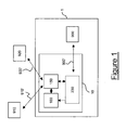
- Figure 1 schematically shows a system 1 according to an embodiment of the present invention.
- the system 1 preferably comprises a device 10 and a control module 900.
- the device 10 comprises a user input-output module 100, a first wireless module 150 and a second wireless module 230.
- the device 10 may comprise other modules or components, which are not shown in Figure 1 since they are not relevant to the present description.
- the first wireless module 150 is suitable for connecting the device 10 to one of a first further device 910 and a second further device 920 through one of a first wireless connection 910' and a second wireless connection 920'.
- the second wireless module 230 is suitable for connecting the device 10 to the control module 900 through a third wireless connection 900'.
- the device 10 may be a headset, while the first further device 910 may be a mobile phone and the second further device 920 may be a computer.
- the device 10 may be a computer, while the first further device 910 may be a first printer and the second further device 920 may be a second printer.
- control module 900 is shown as a stand-alone module, according to advantageous embodiments not shown in the drawings, the control module 900 may be integral either with the first further device 910, or the second further device 920, or the device 10 itself.
- control module 900 is suitable for executing a service logic and, according to the outcome of the service logic, to control the device 10 (and, in particular, the first wireless module 150) through the second wireless module 230.
- the first wireless module 150 preferably comprises a first microcontroller 160, a first temporary memory 170 (implemented e.g. as a RAM), a first permanent memory 180 (implemented e.g. as a ROM) and a first wireless interface 190 provided with a first antenna 190a.
- the first wireless interface 190 with the first antenna 190a is suitable for being connected to a corresponding further wireless interface (not shown in the drawings) of the first further device 910 by means of the first wireless connection 910', thus connecting the device 10 to the first further device 910.
- the first wireless interface 190 with the first antenna 190a is also suitable for being connected to a corresponding further wireless interface (not shown in the drawings) of the second further device 920 by means of the second wireless connection 920', thus connecting the device 10 to the second further device 920.
- the second wireless module 230 preferably comprises a second microprocessor 240, a second temporary memory 250 (implemented e.g. as a RAM), a second permanent memory 260 (implemented e.g. as a ROM) and a second wireless interface 270 provided with a second antenna 270a.
- the second wireless interface 270 with the second antenna 270a is suitable for being connected to a corresponding further wireless interface (not shown in the drawings) of the control module 900 by means of the third wireless connection 900', for connecting the device 10 to the control module 900.
- first temporary memory 170 and the second temporary memory 250 are shown as separate memories, according to advantageous embodiments not shown in the drawings they may be implemented as different areas of a physically unique temporary memory.
- first permanent memory 180 and the second permanent memory 260 are shown as separate memories, according to advantageous embodiments not shown in the drawings they may be implemented as different areas of a physically unique permanent memory.
- the first wireless interface 190 and the second wireless interface 270 are based on different wireless communication technologies.
- the first wireless interface 190 may be based on Bluetooth (thus being suitable for transmitting and receiving radio signals in the 2.4 GHz Bluetooth base-band), while the second wireless interface 270 may be based on Zigbee (thus being suitable for transmitting and receiving radio signals in the 2.4 GHz Zigbee base-band).
- the first wireless interface 190 is suitable for supporting the above mentioned Bluetooth Headset Profile.
- the wireless interfaces (not shown in the drawings) of the first further device 910 and second further device 920 are based on Bluetooth
- the wireless interface (not shown in the drawings) of the control module 900 is based on Zigbee.
- the first wireless interface 190 and the second wireless interface 270 may be based on a same wireless communication technology, e.g. Bluetooth, Zigbee, Wi-Fi and so on.
- a same wireless communication technology e.g. Bluetooth, Zigbee, Wi-Fi and so on.
- both the first wireless interface 190 and the second wireless interface 270 are based on Bluetooth, they preferably support different Bluetooth profiles.
- the first wireless interface 190 may support the above mentioned Bluetooth Headset Profile
- the second wireless interface 270 may support a Bluetooth Serial Profile.
- the first wireless module 150 is connected to the second wireless module 230 by means of a first link 210.
- the first link 210 is a serial link.
- the first link 210 may be implemented as a UART ("Universal Asynchronous Receiver/Transmitter).
- the user input-output module 100 comprises a user input block 110 by means of which the user may input data into the device 10.
- the user.input block 110 may comprise a microphone.
- the user input-output module 100 comprises a user output block 120, by means of which the device 10 may output data to the user.
- the user output block 120 may comprise a speaker.
- the user input-output module 100 preferably comprises also a codec 130.
- the codec 130 decodes data received from the first wireless module 150 so that they can be output by the user output block 120.
- the codec 130 encodes data input by the user through the user input block 110 so that they can be forwarded to and processed by the first wireless module 150.
- the codec PCM preferably is suitable to perform a PCM ("Pulse Code Modulation") on voice data input by the user through the microphone 110.
- the user input-output module 100 is preferably connected to the first wireless module 150 by means of a second link 140 and to the second wireless module 230 by means of a third link 200.
- the third link 200 is implemented as a synchronous serial interface, such as for instance an SPI (Serial Peripheral Interface).
- the user input-output module 100, the first wireless module 150 and the second wireless module 230 are preferably enclosed in a same package.
- the user input-output module 100 may be enclosed in a first package, while the first wireless module 150 and the second wireless module 230 may be enclosed in a second package, the first and second package being connected by means of the second and third links 140 and 200.
- the first package may include only the user input block 110 and the user output block 120, while the PCM codec 130 is enclosed within the second package and is connected by means of a wire to the first package. This advantageously allows to provide a first package with a particularly small size.
- the first package advantageously includes only a microphone 110 and a speaker 120, so that it may have the shape and size e.g. of a hearing aid device, which may be advantageously placed in the user's ear.
- a user has the device 10 (e.g. a headset), which may be connected either to the first further device 910 (e.g. his mobile phone) or to the second further device 920 (e.g. his computer).
- the device 10 e.g. a headset
- the first further device 910 e.g. his mobile phone
- the second further device 920 e.g. his computer
- the first wireless interface 190 and the wireless interfaces of the first further device 910 and second further device 920 are Bluetooth interfaces.
- the user has performed the above mentioned pairing procedure, thus recording the wireless interfaces of the first further device 910 and second further device 920 as "trusted" interfaces at the first wireless interface 190, and recording the first wireless interface 190 as a "trusted” interface at the wireless interfaces of the first further device 910 and second further device 920.
- the user has subscribed a service according to which, when the device 10 is connected to the first further device 910 and a predetermined event occurs, the device 10 is automatically disconnected from the first further device 910 and automatically connected to the second further device 920.
- Examples of such services have been reported above, i.e.: automatically disconnecting a headset connected to a mobile phone and automatically connecting it to a computer when an incoming call is detected by the telephone software application running on the computer, or automatically disconnecting a computer connected to a first printer and automatically connecting it to a second printer when the detected position of the computer is nearer to the second printer.
- the operation of subscribing the service will not be described, since it is not relevant to the present description.
- the control module 900 is located within the coverage area of the second wireless interface 270.
- the operation of activating the subscribed service will not be described in detail, since it is not relevant to the present description.
- the activation of the subscribed service induces the control device 900 to execute the service logic suitable for implementing the subscribed service.
- the first wireless interface 910 When the user switches on the device 10, the first wireless interface 910 also switches on. The wireless interface of the first further device 910 then detects it and transmits to it a request of connection R1 (step 300). Since the wireless interface of the first further device 910 is a "trusted" interface at the first wireless interface 190, the first wireless interface 190 accepts the request of connection (step 500), thus allowing activation of the first wireless connection 910'.
- the first wireless module 150 communicates to the second wireless module 230 that the first wireless connection 910' has been activated.
- the wireless module 230 transmits to the control module 900 a message M1 informing the control module 900 that the device 10 is presently connected to the first further device 910 (step 501).
- the message M1 comprises one or more of the following information: an identifier of the device 10, a wireless address (e.g. a MAC address) of the wireless interface of the first further device 910, and date and time at which the request of connection R1 has been received at the device 10.
- the control module 900 receives such a message M1 and stores its content (step 600).
- the device 10 and the first further device 910 may communicate (steps 310 and 520).
- the device 10 is a headset
- the first further device 910 is a mobile phone and their wireless interfaces are Bluetooth interfaces
- the communication between the device 10 and the first further device 910 takes place according to the above mentioned Bluetooth Headset Profile, i.e. the device 10 and the first further device 910 exchange voice signals encoded according to PCM.
- the second further device 920 enters the coverage area of the first wireless interface 190.
- the second further device 920 is the computer of the user, which is located e.g. in the user's office, the second further device 920 enters the coverage area of the first wireless interface 190 when the user, with his headset 10 and his mobile phone 910, enters his office (if the computer is switched on).
- the second further device 920 When the second further device 920 enters the coverage area of the first wireless interface 190, it preferably transmits to it a request of connection R2 (step 400).
- the device 10 receives the request of connection R2 from the second further device 920 by means of the first wireless module 150, which forwards it to the second wireless module 230.
- the second wireless module 230 transmits to the control module 900 a message M2 informing the control module 900 that the second further device 920 is now located within the coverage area of the first wireless interface 190, and is therefore available for activating a connection with it (step 530).
- the message M2 comprises one or more of the following information: an identifier of the device 10, a wireless address (e.g. a MAC address) of the wireless interface of the second further device 920, and date and time at which the request of connection R2 has been received at the device 10.
- the control module 900 receives such a message M2 and stores its content (step 610). Further, preferably, during step 530 the device 10 does not accept the request of connection R2 received from the second further device 920.
- the second further device 920 preferably periodically repeats the transmission of the request of connection R2 to the device 10 (step 410). However, the device 10 continues not accepting such a request of connection R2 (step 540).
- the control module 900 which is running the service logic controlling the service subscribed by the user, determines that the event suitable to trigger disconnection of the device 10 from the first further device 910 and connection to the second further device 920 has occurred. Examples of such event are e.g., by referring to the above examples, detection of an incoming call by the telephone software application running on the computer, or detection of a nearer printer.
- control module 900 transmits to the second wireless module 230 of the device 10 a command C1 to disconnect from the first further device 910 (step 620).
- the second wireless module 230 forwards it to the first wireless module 150, which then transmits a request of disconnection R3 to the first further device 910 (step 320), so the first further device 910 disconnects from the device 10 (step 320).
- the second further device 920 is still located within the coverage area of the first wireless interface 190, the second further device 920 is still periodically repeating the transmission of the request of connection R2 to the device 10.
- the first time the first wireless module 150 receives from the second further device 920 the request of connection R2 after the first wireless connection 910' with the first further device 910 has been deactivated (step 420), since the wireless interface of the second further device 920 is a "trusted" interface at the first wireless interface 190, the first wireless interface 190 accepts the request of connection R2 (step 560), thus allowing activation of the second wireless connection 920'.
- the first wireless module 150 communicates to the second wireless module 230 that the second wireless connection 920' has been activated.
- the wireless module 230 transmits to the control module 900 a message M3 informing the control module 900 that the device 10 is presently connected to the second further device 920 (step 570).
- the message M3 comprises one or more of the following information: an identifier of the device 10, a wireless address of the wireless interface of the second further device 920, and date and time at which the accepted request of connection R2 has been received at the device 10.
- the control module 900 receives such a message M3 and stores its content (step 630).
- the device 10 and the second further device 920 may communicate (steps 430 and 580).
- the device 10 if the device 10 is a headset, the second further device 920 is a computer and their wireless interfaces are Bluetooth interfaces, the device 10 preferably receives from the second further device 920 the streaming of an audio file.
- the communication between the device 10 and the second further device 920 may terminate when one of the following events occurs:
- the system described above advantageously allows, when the first wireless interface 190 is connected to the first further device 910 (namely, to its wireless interface), to automatically switch connection of the first wireless interface 190, i.e. to disconnect the first wireless interface 190 from the first further device 910 (namely, from its wireless interface) and connect it to the second further device 920 (namely, to its wireless interface), without requiring any manual intervention by the user of the device 10.
- the device 10 (in particular, its first wireless interface 190) is advantageously automatically controlled by the service logic run on the control device 900. Since the wireless interface of the second further device 920 is recorded as a "trusted" interface at the first wireless interface 190, the switch of the connection only requires that the control device 900 instructs the first wireless interface 190 to disconnect from the first further device 910. This operation is automatically performed by the system, since it is based on an exchange of information between the device 10 (in particular, its second wireless module 230) and the control module 900, without requiring any intervention by the user.
- the first wireless interface 190 is disconnected from the first further device 910, as soon as it receives a request for connection R2 from the wireless interface of the second further device 920, it automatically accepts it, thus allowing to connect the device 10 to the second further device 920.
- this operation therefore is automatically performed by the system, since it is based on an exchange of information between the first wireless interface 190 and the wireless interface of the second further device 920.
Landscapes
- Engineering & Computer Science (AREA)
- Computer Networks & Wireless Communication (AREA)
- Signal Processing (AREA)
- Mobile Radio Communication Systems (AREA)
- Communication Control (AREA)
Claims (15)
- System (1) mit einer Vorrichtung (10) und einem Kontrollmodul (900), wobei die Vorrichtung (10) eine erste drahtlose Schnittstelle (190) aufweist, die in der Lage ist, die Vorrichtung (10) mit einer ersten weiteren Vorrichtung (910) und einer zweiten drahtlosen Schnittstelle (270) zum Verbinden der Vorrichtung (10) mit dem Kontrollmodul (900) zu verbinden, wobei:die ersten drahtlose Schnittstelle (190) ausgebildet ist, um festzustellen, dass eine zweite weitere Vorrichtung (920) innerhalb eines Abdeckungsbereiches lokalisiert ist, und um diese Information an die zweite drahtlose Schnittstelle (270) zu kommunizieren;die zweite drahtlose Schnittstelle (270) ausgebildet ist, um an das Kontrollmodul (900) eine Nachricht (M2), die anzeigt, dass die zweite weitere Vorrichtung (920) innerhalb des Abdeckungsbereiches lokalisiert ist, zu übermitteln;das Kontrollmodul (900) ausgebildet ist, um eine Servicelogik auszuführen, um zu bestimmen, ob ein Ereignis, welches eine Verbindungsunterbrechung der Vorrichtung (10) von der ersten weiteren Vorrichtung (910) und eine Verbindung zu der zweiten weiteren Vorrichtung (920) auslöst, aufgetreten ist und, wenn dies der Fall ist, an die zweite drahtlose Schnittstelle (270) ein Kommando (C1) zum Trennen der ersten drahtlosen Schnittstelle (190) von der ersten weiteren Vorrichtung (910) zu übermitteln; unddie erste drahtlose Schnittstelle (190) weiter ausgebildet ist, um das Kommando (C1) von der zweiten drahtlosen Schnittstelle (270) zu erhalten, um das Kommando (C1) auszuführen, um dadurch automatisch die Vorrichtung (10) von der ersten weiteren Vorrichtung (910) zu trennen und, als Konsequenz der Trennung, eine Verbindungsanfrage (R2), die von der zweiten weiteren Vorrichtung (920) erhalten wird, zu akzeptieren, um dadurch die Vorrichtung (10) mit der zweiten weiteren Vorrichtung (920) zu verbinden.
- System (1) nach Anspruch 1, wobei die erste drahtlose Schnittstelle (190) weiter ausgebildet ist, um als Antwort auf die Verbindungstrennung eine Verbindungsanfrage (R2) anzunehmen, die von der zweiten weiteren Vorrichtung (920) erhalten wurde, um dadurch die Vorrichtung (10) mit der zweiten weiteren Vorrichtung (920) zu verbinden.
- System (1) nach Anspruch 1 oder 2, wobei das Kontrollmodul (900) weiter ausgebildet ist, um eines oder mehrere aus dem Folgenden zu speichern: einen Identifizierer der Vorrichtung (10), eine drahtlose Adresse der ersten weiteren Vorrichtung (10) und ein Datum und eine Zeit, an welcher die Verbindung zwischen der ersten drahtlosen Schnittstelle (190) und der ersten weiteren Vorrichtung (910) aktiviert wurde.
- System (1) nach einem der vorhergehenden Ansprüche, wobei die zweite drahtlose Schnittstelle (270) weiter ausgebildet ist, um in die Nachricht (M2) eines oder mehreres aus dem Folgenden einzuschließen: einen Identifizierer der Vorrichtung (10), eine drahtlose Adresse der zweiten weiteren Vorrichtung (920) und ein Datum und eine Zeit, an welcher die zweite weitere Vorrichtung (920) durch die erste drahtlose Schnittstelle (190) detektiert wurde.
- System (1) nach einem der vorhergehenden Ansprüche, wobei die erste drahtlose Schnittstelle (190) weiter ausgebildet ist, um periodisch Verbindungsanfragen (R2) von der zweiten weiteren Vorrichtung (920) zu erhalten und um die Verbindungsanfragen (R2) nicht zu akzeptieren, wenn die zweite drahtlose Schnittstelle (190) mit der ersten weiteren Vorrichtung (910) verbunden ist.
- System (1) nach einem der vorhergehenden Ansprüche, wobei das Kontrollmodul (900) ausgebildet ist, um festzustellen, ob ein Ereignis aufgetreten ist, welches geeignet ist, um eine Verbindungstrennung der Vorrichtung (10) von der ersten weiteren Vorrichtung (910) und eine Verbindung mit der zweiten weiteren Vorrichtung (920) auszulösen und das Kommando (C1) als Konsequenz des Auftretens zu übertragen.
- System (1) nach einem der vorhergehenden Ansprüche, wobei die zweite drahtlose Schnittstelle (270) weiter ausgebildet ist, um, nachdem die Vorrichtung (10) mit der zweiten weiteren Vorrichtung (920) verbunden wurde, an das Kontrollmodul (900) eine weitere Nachricht (M3) zu übermitteln, um das Kontrollmodul (900) zu informieren, dass die Vorrichtung (10) zur gegenwärtigen Zeit mit der zweiten weiteren Vorrichtung (920) verbunden ist.
- Vorrichtung (10) mit einer drahtlosen Schnittstelle (190), die ausgebildet ist, um die Vorrichtung (10) mit einer ersten weiteren Vorrichtung (910) und einer zweiten drahtlosen Schnittstelle (270) zum Verbinden der Vorrichtung (10) mit einem Kontrollmodul (900) zu verbinden, wobei:die erste drahtlose Schnittstelle (190) ausgebildet ist, um festzustellen, dass eine zweite weitere Vorrichtung (920) innerhalb des Abdeckungsgebietes lokalisiert ist, und um diese Informationen an die zweite drahtlose Schnittstelle (270) zu kommunizieren;die zweite drahtlose Schnittstelle (270) ausgebildet ist, um an das Kontrollmodul (900) eine Nachricht (M2) zu übermitteln, die anzeigt, dass die zweite weitere Vorrichtung (920) in dem Abdeckungsgebiet lokalisiert ist;die zweite drahtlose Schnittstelle (270) ausgebildet ist, um von dem Kontrollmodul (900) ein Kommando (C1) zu erhalten, um die erste drahtlose Schnittstelle (190) von der ersten weiteren Vorrichtung (910) zu trennen, wobei das Kommando (C1) von dem Kontrollmodul (900) übertragen wird, und zwar entsprechend eines Resultates des Ausführens einer Servicelogik, die bestimmt, ob ein Ereignis aufgetreten ist, welches eine Verbindungstrennung der Vorrichtung (10) von der ersten weiteren Vorrichtung (910) und ein Verbinden mit der zweiten weiteren Vorrichtung (920) anzeigt; unddie erste drahtlose Schnittstelle (190) weiter ausgebildet ist, um das Kommando (C1) von der zweiten drahtlosen Schnittstelle (270) zu erhalten, um das Kommando (C1) auszuführen, um dadurch automatisch die Vorrichtung (10) von der ersten weiteren Vorrichtung (910) zu trennen und um eine Verbindungsanfrage (R2) anzunehmen, die als Konsequenz der Trennung von der zweiten weiteren Vorrichtung (920) erhalten wurde, um dadurch die Vorrichtung (10) mit der zweiten weiteren Vorrichtung (920) zu verbinden.
- Verfahren zum automatischen Trennen einer ersten drahtlosen Schnittstelle (190) von einer ersten weiteren Vorrichtung (910) und zum Verbinden derselben mit einer zweiten weiteren Vorrichtung (920), wenn die erste drahtlose Schnittstelle (190) einer Vorrichtung (10) mit der ersten weiteren Vorrichtung (910) verbunden ist, wobei das Verfahren Folgendes umfasst:a) Bereitstellen einer zweiten drahtlosen Schnittstelle (270) für die Vorrichtung (10), die geeignet ist zum Verbinden der Vorrichtung (10) mit einem Kontrollmodul (900);b) Feststellen, und zwar an der ersten drahtlosen Schnittstelle (190), dass die zweite weitere Vorrichtung (920) innerhalb eines Abdeckungsbereiches lokalisiert ist, und Kommunizieren dieser Information an die zweite drahtlose Schnittstelle (270);c) Übertragen von der zweiten drahtlosen Schnittstelle (270) an das Kontrollmodul (900) eine Nachricht (M2), die anzeigt, dass die zweite weitere Vorrichtung (920) innerhalb des Abdeckungsbereiches lokalisiert ist;d) Ausführen einer Servicelogik, und zwar in dem Kontrollmodul (900), um dadurch zu bestimmen, ob ein Ereignis aufgetreten ist, welches in der Lage ist, eine Verbindungstrennung der Vorrichtung (10) von der ersten weiteren Vorrichtung (910) und eine Verbindung mit der zweiten weiteren Vorrichtung (920) auszulösen und, wenn dies der Fall ist, ein Kommando (C1) an die zweite drahtlose Schnittstelle (270) zu übertragen, um die erste drahtlose Schnittstelle (190) von der ersten weiteren Vorrichtung (910) zu trennen; unde) Erhalten des Kommandos (C1) an der ersten drahtlosen Schnittstelle (190) von der zweiten drahtlosen Schnittstelle (270), Ausführen des Kommandos (C1), um dadurch automatisch die Verbindung der Vorrichtung (10) von der ersten weiteren Vorrichtung (910) zu trennen, und Annahme einer Verbindungsanfrage als Konsequenz der Verbindungstrennung, die von der zweiten weiteren Vorrichtung (920) erhalten wird, um dadurch die Vorrichtung (10) mit der zweiten weiteren Vorrichtung (920) zu verbinden.
- Verfahren nach Anspruch 9, wobei weiter Folgendes umfasst ist: vor dem Schritt b), Kennzeichnen der ersten weiteren Vorrichtung (910) und der zweiten weiteren Vorrichtung (920) als vertrauenswürdige Vorrichtungen an der ersten drahtlosen Schnittstelle (190).
- Verfahren nach Anspruch 9 oder 10, wobei weiter Folgendes umfasst ist: vor dem Schritt b) wird an dem Kontrollmodul (900) eines oder mehreres aus dem Folgenden gespeichert: ein Identifizierer der Vorrichtung (10), eine erste drahtlose Adresse der ersten weiteren Vorrichtung (910) und ein Datum und eine Zeit, an welche eine Verbindung zwischen der ersten drahtlosen Schnittstelle (190) und der ersten weiteren Vorrichtung (910) aktiviert wurde.
- Verfahren nach einem der Ansprüche 9-10, wobei der Schritt c) umfasst, dass die Nachricht (M2) eines oder mehreres aus dem Folgenden umfasst: ein Identifizierer der Vorrichtung (10), eine zweite drahtlose Adresse der zweiten weiteren Vorrichtung (920) und ein Datum und eine Zeit, zu welcher die zweite weitere Vorrichtung (920) durch die erste drahtlose Schnittstelle (190) detektiert wurde.
- Verfahren nach einem der Ansprüche 9-12, wobei weiter Folgendes umfasst ist: nach dem Schritt c) und vor dem Schritt e): periodisches Erhalten von Verbindungsanfragen (R2) durch die erste drahtlose Schnittstelle (190) von der zweiten weiteren Vorrichtung (920) und Ablehnen der Verbindungsanfragen (R2).
- Verfahren nach einem der Ansprüche 9-13, wobei der Schritt c) umfasst, dass ein Auftreten eines Ereignis festgestellt wird, welches geeignet ist, eine Verbindungstrennung der Vorrichtung (10) von der ersten weiteren Vorrichtung (910) und ein Verbinden mit der zweiten weiteren Vorrichtung (920) auszulösen.
- Verfahren nach einem der Ansprüche 9-14, wobei weiter Folgendes umfasst ist: nach dem Schritt e): Übertragen einer weiteren Nachricht (M3) von der zweiten drahtlosen Schnittstelle (270) an das Kontrollmodul (900), um das Kontrollmodul (900) zu informieren, dass die Vorrichtung (10) zur gegenwärtigen Zeit mit der zweiten weiteren Vorrichtung (920) verbunden ist.
Applications Claiming Priority (1)
| Application Number | Priority Date | Filing Date | Title |
|---|---|---|---|
| PCT/EP2008/058352 WO2010000293A1 (en) | 2008-06-30 | 2008-06-30 | System and method for automatically switching connection of a wireless interface |
Publications (2)
| Publication Number | Publication Date |
|---|---|
| EP2294872A1 EP2294872A1 (de) | 2011-03-16 |
| EP2294872B1 true EP2294872B1 (de) | 2012-02-08 |
Family
ID=40467116
Family Applications (1)
| Application Number | Title | Priority Date | Filing Date |
|---|---|---|---|
| EP08774507A Active EP2294872B1 (de) | 2008-06-30 | 2008-06-30 | System und verfahren zum automatischen umschalten der verbindung einer drahtlosen schnittstelle |
Country Status (4)
| Country | Link |
|---|---|
| US (1) | US8620216B2 (de) |
| EP (1) | EP2294872B1 (de) |
| AT (1) | ATE545302T1 (de) |
| WO (1) | WO2010000293A1 (de) |
Families Citing this family (20)
| Publication number | Priority date | Publication date | Assignee | Title |
|---|---|---|---|---|
| US8504629B2 (en) * | 2010-07-01 | 2013-08-06 | Plantronics, Inc. | Connection device and protocol |
| US8750799B2 (en) * | 2010-09-30 | 2014-06-10 | Apple Inc. | Wireless accessory device pairing determination for multiple host devices |
| US9450759B2 (en) | 2011-04-05 | 2016-09-20 | Apple Inc. | Apparatus and methods for controlling distribution of electronic access clients |
| EP2568763B1 (de) * | 2011-09-07 | 2016-07-20 | National Chung-Shan Institute of Science and Technology | Drahtlose Vollduplex-Sprachrundfunksystem mit Kanalwechsel und Interferenzbeständigkeit |
| US10516774B2 (en) * | 2012-02-09 | 2019-12-24 | Apple Inc. | Method for configuring a wireless device |
| US10152861B2 (en) | 2012-02-09 | 2018-12-11 | Apple Inc. | Wireless security camera system |
| JP5799880B2 (ja) * | 2012-04-04 | 2015-10-28 | 株式会社デンソー | 通信装置、プログラムおよび通信確立方法 |
| US8914895B1 (en) * | 2012-09-25 | 2014-12-16 | Emc Corporation | Managing verification of input data |
| JP6179157B2 (ja) * | 2013-03-27 | 2017-08-16 | ブラザー工業株式会社 | 情報処理装置、通信端末装置および情報処理装置のプログラム |
| US9924297B2 (en) | 2014-04-28 | 2018-03-20 | International Business Machines Corporation | Timed and variable duration for multiple device synching |
| US9769858B2 (en) | 2014-05-30 | 2017-09-19 | Apple Inc. | Seamless connectivity between hearing aid and multiple devices |
| JP6246353B2 (ja) * | 2014-06-09 | 2017-12-13 | 株式会社Nttドコモ | 通信装置及び通信制御方法 |
| US9924010B2 (en) | 2015-06-05 | 2018-03-20 | Apple Inc. | Audio data routing between multiple wirelessly connected devices |
| JP6608190B2 (ja) * | 2015-06-23 | 2019-11-20 | キヤノン株式会社 | 情報端末、その制御方法、及びプログラム |
| JP6701523B2 (ja) * | 2016-09-29 | 2020-05-27 | ブラザー工業株式会社 | 携帯型印刷装置 |
| KR20180038166A (ko) * | 2016-10-06 | 2018-04-16 | 삼성전자주식회사 | 디스플레이 장치, 디스플레이 장치와 연결 가능한 전자 장치 및 이들의 제어 방법 |
| US10437343B2 (en) * | 2017-01-06 | 2019-10-08 | Samsung Electronics Co., Ltd. | Augmented reality control of internet of things devices |
| WO2018144026A1 (en) * | 2017-02-06 | 2018-08-09 | Hewlett-Packard Development Company, L.P. | Media content control of source devices on sink devices |
| KR102458486B1 (ko) | 2017-02-09 | 2022-10-25 | 삼성전자 주식회사 | 근거리 무선 통신 시스템에서 디바이스의 연결 방법 및 장치 |
| EP4206901A4 (de) * | 2021-01-21 | 2024-04-10 | Samsung Electronics Co., Ltd. | Tragbare elektronische vorrichtung, die informationen von einer externen tragbaren elektronischen vorrichtung empfängt, und betriebsverfahren dafür |
Family Cites Families (14)
| Publication number | Priority date | Publication date | Assignee | Title |
|---|---|---|---|---|
| JPH09187060A (ja) | 1995-12-28 | 1997-07-15 | Nec Corp | ワイヤレスイヤホン付き携帯電話機 |
| US6834192B1 (en) * | 2000-07-03 | 2004-12-21 | Nokia Corporation | Method, and associated apparatus, for effectuating handover of communications in a bluetooth, or other, radio communication system |
| JP4617022B2 (ja) * | 2001-05-08 | 2011-01-19 | キヤノン株式会社 | 通信装置 |
| US7202783B2 (en) * | 2001-12-18 | 2007-04-10 | Intel Corporation | Method and system for identifying when a first device is within a physical range of a second device |
| JP2003347956A (ja) * | 2002-05-28 | 2003-12-05 | Toshiba Corp | オーディオ出力装置およびその制御方法 |
| US7039408B2 (en) * | 2002-06-03 | 2006-05-02 | Interdigital Technology Corporation | Method and apparatus for interconnection of personal area networks (PANs) |
| US20040014422A1 (en) * | 2002-07-19 | 2004-01-22 | Nokia Corporation | Method and system for handovers using service description data |
| JP3696192B2 (ja) | 2002-09-27 | 2005-09-14 | 株式会社東芝 | 電子機器および同電子機器の接続先切替え方法 |
| US7668545B2 (en) * | 2003-10-03 | 2010-02-23 | Qualcomm Incorporated | Maintaining data connectivity for handoffs between compression-enabled and compression-disabled communication systems |
| US7386275B2 (en) * | 2005-03-11 | 2008-06-10 | Dell Products Llp | Systems and methods for managing out-of-band device connection |
| US7577459B2 (en) | 2005-05-11 | 2009-08-18 | Nokia Corporation | Establishing a communication link |
| US7636549B2 (en) * | 2006-04-21 | 2009-12-22 | Abbott Medical Optics Inc. | Automated bonding for wireless devices |
| US8112794B2 (en) * | 2006-07-17 | 2012-02-07 | Research In Motion Limited | Management of multiple connections to a security token access device |
| KR100962117B1 (ko) * | 2007-05-25 | 2010-06-10 | 삼성전자주식회사 | 광대역 무선통신 시스템에서 무선 주파수 식별자를 이용한소형 기지국으로의 단말 등록 장치 및 방법 |
-
2008
- 2008-06-30 AT AT08774507T patent/ATE545302T1/de active
- 2008-06-30 WO PCT/EP2008/058352 patent/WO2010000293A1/en not_active Ceased
- 2008-06-30 EP EP08774507A patent/EP2294872B1/de active Active
- 2008-06-30 US US13/002,258 patent/US8620216B2/en active Active
Also Published As
| Publication number | Publication date |
|---|---|
| US20110151788A1 (en) | 2011-06-23 |
| ATE545302T1 (de) | 2012-02-15 |
| EP2294872A1 (de) | 2011-03-16 |
| WO2010000293A1 (en) | 2010-01-07 |
| US8620216B2 (en) | 2013-12-31 |
Similar Documents
| Publication | Publication Date | Title |
|---|---|---|
| EP2294872B1 (de) | System und verfahren zum automatischen umschalten der verbindung einer drahtlosen schnittstelle | |
| EP3002935B1 (de) | Vorrichtung und verfahren zur steuerung eines eingebauten mikrofons in einem tragbaren endgerät | |
| JP5042629B2 (ja) | 統合型セルラ/pcs−pots通信システム | |
| KR100721641B1 (ko) | 콜 개시에 대한 무선 요구를 거절하기 위한 방법 및 장치 | |
| EP1606923B1 (de) | Drahtloses freihandsystem mit stillerbenutzersignalisierung | |
| US8073137B2 (en) | Audio headset | |
| EP1324550B1 (de) | Tragbares Endgerät mit kombinierter Kommunikation über Funk mit geringer Reichweite für Direktverbindungen und zellularen Mobilfunk | |
| KR100395332B1 (ko) | 블루투스 무선장치를 구비한 통신 단말간의 링크 연결 방법 | |
| EP1176783A2 (de) | Verfahren und Vorrichtung zur Übertragung von Datenstromen zwischen einem Slave und einem Master in einem Mobilsystem mit kurzer Übertragungsreichweite | |
| JP2002186022A (ja) | ウェアブル端末システム | |
| US20110143664A1 (en) | System and method for bluetooth push to talk | |
| EP1404067A2 (de) | Elektronisches Gerät und Verfahren zur Vermittlung des Bestimmungsorts einer drahtlosen Verbindung | |
| WO2003065756A2 (en) | Method for maintaining communication with a device | |
| WO2007129230A2 (en) | Method and apparatus for routing content for a mobile phone over an alternative wireless network | |
| CN101150335A (zh) | 实现多种功能的蓝牙电话终端设备 | |
| JP2006279586A (ja) | 携帯通信機器およびその携帯通信機器を含む通信システム | |
| TW200529042A (en) | Wireless peripheral and related system capable of alarming wireless connection status | |
| JP7424187B2 (ja) | クレードルおよび無線通信システム | |
| US20030218975A1 (en) | Communication terminal, operating equipment, communication system, and communication control method | |
| KR20030004760A (ko) | 블루투스를 이용한 이동통신 단말기의 착신 신호 인식 및통화 장치 및 그 방법 | |
| JP2004120126A (ja) | Bluetooth音声通信装置 | |
| JPH11234746A (ja) | デジタルコードレス電話システム |
Legal Events
| Date | Code | Title | Description |
|---|---|---|---|
| PUAI | Public reference made under article 153(3) epc to a published international application that has entered the european phase |
Free format text: ORIGINAL CODE: 0009012 |
|
| 17P | Request for examination filed |
Effective date: 20110114 |
|
| AK | Designated contracting states |
Kind code of ref document: A1 Designated state(s): AT BE BG CH CY CZ DE DK EE ES FI FR GB GR HR HU IE IS IT LI LT LU LV MC MT NL NO PL PT RO SE SI SK TR |
|
| AX | Request for extension of the european patent |
Extension state: AL BA MK RS |
|
| GRAP | Despatch of communication of intention to grant a patent |
Free format text: ORIGINAL CODE: EPIDOSNIGR1 |
|
| DAX | Request for extension of the european patent (deleted) | ||
| GRAS | Grant fee paid |
Free format text: ORIGINAL CODE: EPIDOSNIGR3 |
|
| GRAA | (expected) grant |
Free format text: ORIGINAL CODE: 0009210 |
|
| AK | Designated contracting states |
Kind code of ref document: B1 Designated state(s): AT BE BG CH CY CZ DE DK EE ES FI FR GB GR HR HU IE IS IT LI LT LU LV MC MT NL NO PL PT RO SE SI SK TR |
|
| REG | Reference to a national code |
Ref country code: GB Ref legal event code: FG4D |
|
| REG | Reference to a national code |
Ref country code: AT Ref legal event code: REF Ref document number: 545302 Country of ref document: AT Kind code of ref document: T Effective date: 20120215 Ref country code: CH Ref legal event code: EP |
|
| REG | Reference to a national code |
Ref country code: DE Ref legal event code: R096 Ref document number: 602008013293 Country of ref document: DE Effective date: 20120405 |
|
| REG | Reference to a national code |
Ref country code: NL Ref legal event code: VDEP Effective date: 20120208 |
|
| LTIE | Lt: invalidation of european patent or patent extension |
Effective date: 20120208 |
|
| PG25 | Lapsed in a contracting state [announced via postgrant information from national office to epo] |
Ref country code: LT Free format text: LAPSE BECAUSE OF FAILURE TO SUBMIT A TRANSLATION OF THE DESCRIPTION OR TO PAY THE FEE WITHIN THE PRESCRIBED TIME-LIMIT Effective date: 20120208 Ref country code: NL Free format text: LAPSE BECAUSE OF FAILURE TO SUBMIT A TRANSLATION OF THE DESCRIPTION OR TO PAY THE FEE WITHIN THE PRESCRIBED TIME-LIMIT Effective date: 20120208 Ref country code: IS Free format text: LAPSE BECAUSE OF FAILURE TO SUBMIT A TRANSLATION OF THE DESCRIPTION OR TO PAY THE FEE WITHIN THE PRESCRIBED TIME-LIMIT Effective date: 20120608 Ref country code: NO Free format text: LAPSE BECAUSE OF FAILURE TO SUBMIT A TRANSLATION OF THE DESCRIPTION OR TO PAY THE FEE WITHIN THE PRESCRIBED TIME-LIMIT Effective date: 20120508 Ref country code: HR Free format text: LAPSE BECAUSE OF FAILURE TO SUBMIT A TRANSLATION OF THE DESCRIPTION OR TO PAY THE FEE WITHIN THE PRESCRIBED TIME-LIMIT Effective date: 20120208 |
|
| PG25 | Lapsed in a contracting state [announced via postgrant information from national office to epo] |
Ref country code: PT Free format text: LAPSE BECAUSE OF FAILURE TO SUBMIT A TRANSLATION OF THE DESCRIPTION OR TO PAY THE FEE WITHIN THE PRESCRIBED TIME-LIMIT Effective date: 20120608 Ref country code: BE Free format text: LAPSE BECAUSE OF FAILURE TO SUBMIT A TRANSLATION OF THE DESCRIPTION OR TO PAY THE FEE WITHIN THE PRESCRIBED TIME-LIMIT Effective date: 20120208 Ref country code: LV Free format text: LAPSE BECAUSE OF FAILURE TO SUBMIT A TRANSLATION OF THE DESCRIPTION OR TO PAY THE FEE WITHIN THE PRESCRIBED TIME-LIMIT Effective date: 20120208 Ref country code: PL Free format text: LAPSE BECAUSE OF FAILURE TO SUBMIT A TRANSLATION OF THE DESCRIPTION OR TO PAY THE FEE WITHIN THE PRESCRIBED TIME-LIMIT Effective date: 20120208 Ref country code: FI Free format text: LAPSE BECAUSE OF FAILURE TO SUBMIT A TRANSLATION OF THE DESCRIPTION OR TO PAY THE FEE WITHIN THE PRESCRIBED TIME-LIMIT Effective date: 20120208 Ref country code: GR Free format text: LAPSE BECAUSE OF FAILURE TO SUBMIT A TRANSLATION OF THE DESCRIPTION OR TO PAY THE FEE WITHIN THE PRESCRIBED TIME-LIMIT Effective date: 20120509 |
|
| REG | Reference to a national code |
Ref country code: AT Ref legal event code: MK05 Ref document number: 545302 Country of ref document: AT Kind code of ref document: T Effective date: 20120208 |
|
| PG25 | Lapsed in a contracting state [announced via postgrant information from national office to epo] |
Ref country code: CY Free format text: LAPSE BECAUSE OF FAILURE TO SUBMIT A TRANSLATION OF THE DESCRIPTION OR TO PAY THE FEE WITHIN THE PRESCRIBED TIME-LIMIT Effective date: 20120208 |
|
| PG25 | Lapsed in a contracting state [announced via postgrant information from national office to epo] |
Ref country code: DK Free format text: LAPSE BECAUSE OF FAILURE TO SUBMIT A TRANSLATION OF THE DESCRIPTION OR TO PAY THE FEE WITHIN THE PRESCRIBED TIME-LIMIT Effective date: 20120208 Ref country code: SI Free format text: LAPSE BECAUSE OF FAILURE TO SUBMIT A TRANSLATION OF THE DESCRIPTION OR TO PAY THE FEE WITHIN THE PRESCRIBED TIME-LIMIT Effective date: 20120208 Ref country code: EE Free format text: LAPSE BECAUSE OF FAILURE TO SUBMIT A TRANSLATION OF THE DESCRIPTION OR TO PAY THE FEE WITHIN THE PRESCRIBED TIME-LIMIT Effective date: 20120208 Ref country code: SE Free format text: LAPSE BECAUSE OF FAILURE TO SUBMIT A TRANSLATION OF THE DESCRIPTION OR TO PAY THE FEE WITHIN THE PRESCRIBED TIME-LIMIT Effective date: 20120208 Ref country code: CZ Free format text: LAPSE BECAUSE OF FAILURE TO SUBMIT A TRANSLATION OF THE DESCRIPTION OR TO PAY THE FEE WITHIN THE PRESCRIBED TIME-LIMIT Effective date: 20120208 Ref country code: RO Free format text: LAPSE BECAUSE OF FAILURE TO SUBMIT A TRANSLATION OF THE DESCRIPTION OR TO PAY THE FEE WITHIN THE PRESCRIBED TIME-LIMIT Effective date: 20120208 |
|
| PG25 | Lapsed in a contracting state [announced via postgrant information from national office to epo] |
Ref country code: SK Free format text: LAPSE BECAUSE OF FAILURE TO SUBMIT A TRANSLATION OF THE DESCRIPTION OR TO PAY THE FEE WITHIN THE PRESCRIBED TIME-LIMIT Effective date: 20120208 |
|
| PLBE | No opposition filed within time limit |
Free format text: ORIGINAL CODE: 0009261 |
|
| STAA | Information on the status of an ep patent application or granted ep patent |
Free format text: STATUS: NO OPPOSITION FILED WITHIN TIME LIMIT |
|
| 26N | No opposition filed |
Effective date: 20121109 |
|
| PG25 | Lapsed in a contracting state [announced via postgrant information from national office to epo] |
Ref country code: AT Free format text: LAPSE BECAUSE OF FAILURE TO SUBMIT A TRANSLATION OF THE DESCRIPTION OR TO PAY THE FEE WITHIN THE PRESCRIBED TIME-LIMIT Effective date: 20120208 Ref country code: MC Free format text: LAPSE BECAUSE OF NON-PAYMENT OF DUE FEES Effective date: 20120630 |
|
| REG | Reference to a national code |
Ref country code: CH Ref legal event code: PL |
|
| REG | Reference to a national code |
Ref country code: CH Ref legal event code: PL |
|
| REG | Reference to a national code |
Ref country code: DE Ref legal event code: R097 Ref document number: 602008013293 Country of ref document: DE Effective date: 20121109 |
|
| REG | Reference to a national code |
Ref country code: IE Ref legal event code: MM4A |
|
| PG25 | Lapsed in a contracting state [announced via postgrant information from national office to epo] |
Ref country code: IE Free format text: LAPSE BECAUSE OF NON-PAYMENT OF DUE FEES Effective date: 20120630 Ref country code: CH Free format text: LAPSE BECAUSE OF NON-PAYMENT OF DUE FEES Effective date: 20120630 Ref country code: LI Free format text: LAPSE BECAUSE OF NON-PAYMENT OF DUE FEES Effective date: 20120630 Ref country code: ES Free format text: LAPSE BECAUSE OF FAILURE TO SUBMIT A TRANSLATION OF THE DESCRIPTION OR TO PAY THE FEE WITHIN THE PRESCRIBED TIME-LIMIT Effective date: 20120519 |
|
| PG25 | Lapsed in a contracting state [announced via postgrant information from national office to epo] |
Ref country code: BG Free format text: LAPSE BECAUSE OF FAILURE TO SUBMIT A TRANSLATION OF THE DESCRIPTION OR TO PAY THE FEE WITHIN THE PRESCRIBED TIME-LIMIT Effective date: 20120508 Ref country code: MT Free format text: LAPSE BECAUSE OF FAILURE TO SUBMIT A TRANSLATION OF THE DESCRIPTION OR TO PAY THE FEE WITHIN THE PRESCRIBED TIME-LIMIT Effective date: 20120208 |
|
| PG25 | Lapsed in a contracting state [announced via postgrant information from national office to epo] |
Ref country code: TR Free format text: LAPSE BECAUSE OF FAILURE TO SUBMIT A TRANSLATION OF THE DESCRIPTION OR TO PAY THE FEE WITHIN THE PRESCRIBED TIME-LIMIT Effective date: 20120208 |
|
| PG25 | Lapsed in a contracting state [announced via postgrant information from national office to epo] |
Ref country code: LU Free format text: LAPSE BECAUSE OF NON-PAYMENT OF DUE FEES Effective date: 20120630 |
|
| PG25 | Lapsed in a contracting state [announced via postgrant information from national office to epo] |
Ref country code: HU Free format text: LAPSE BECAUSE OF FAILURE TO SUBMIT A TRANSLATION OF THE DESCRIPTION OR TO PAY THE FEE WITHIN THE PRESCRIBED TIME-LIMIT Effective date: 20080630 |
|
| REG | Reference to a national code |
Ref country code: FR Ref legal event code: PLFP Year of fee payment: 9 |
|
| REG | Reference to a national code |
Ref country code: FR Ref legal event code: PLFP Year of fee payment: 10 |
|
| REG | Reference to a national code |
Ref country code: FR Ref legal event code: PLFP Year of fee payment: 11 |
|
| P01 | Opt-out of the competence of the unified patent court (upc) registered |
Effective date: 20230529 |
|
| P02 | Opt-out of the competence of the unified patent court (upc) changed |
Effective date: 20230604 |
|
| PGFP | Annual fee paid to national office [announced via postgrant information from national office to epo] |
Ref country code: DE Payment date: 20250618 Year of fee payment: 18 |
|
| PGFP | Annual fee paid to national office [announced via postgrant information from national office to epo] |
Ref country code: GB Payment date: 20250625 Year of fee payment: 18 |
|
| PGFP | Annual fee paid to national office [announced via postgrant information from national office to epo] |
Ref country code: FR Payment date: 20250620 Year of fee payment: 18 |
|
| PGFP | Annual fee paid to national office [announced via postgrant information from national office to epo] |
Ref country code: IT Payment date: 20250630 Year of fee payment: 18 |