EP2294979B1 - Verfahren und elektronisches medizinisches Gerät für simultane Messung sowie Impedanz und Biopotenzialsignal - Google Patents
Verfahren und elektronisches medizinisches Gerät für simultane Messung sowie Impedanz und Biopotenzialsignal Download PDFInfo
- Publication number
- EP2294979B1 EP2294979B1 EP10152299.3A EP10152299A EP2294979B1 EP 2294979 B1 EP2294979 B1 EP 2294979B1 EP 10152299 A EP10152299 A EP 10152299A EP 2294979 B1 EP2294979 B1 EP 2294979B1
- Authority
- EP
- European Patent Office
- Prior art keywords
- signal
- input
- frequency
- impedance
- biopotential
- Prior art date
- Legal status (The legal status is an assumption and is not a legal conclusion. Google has not performed a legal analysis and makes no representation as to the accuracy of the status listed.)
- Active
Links
Images




Classifications
-
- A—HUMAN NECESSITIES
- A61—MEDICAL OR VETERINARY SCIENCE; HYGIENE
- A61B—DIAGNOSIS; SURGERY; IDENTIFICATION
- A61B5/00—Measuring for diagnostic purposes; Identification of persons
- A61B5/05—Detecting, measuring or recording for diagnosis by means of electric currents or magnetic fields; Measuring using microwaves or radio waves
- A61B5/053—Measuring electrical impedance or conductance of a portion of the body
- A61B5/0531—Measuring skin impedance
-
- A—HUMAN NECESSITIES
- A61—MEDICAL OR VETERINARY SCIENCE; HYGIENE
- A61B—DIAGNOSIS; SURGERY; IDENTIFICATION
- A61B5/00—Measuring for diagnostic purposes; Identification of persons
- A61B5/24—Detecting, measuring or recording bioelectric or biomagnetic signals of the body or parts thereof
- A61B5/30—Input circuits therefor
- A61B5/305—Common mode rejection
-
- A—HUMAN NECESSITIES
- A61—MEDICAL OR VETERINARY SCIENCE; HYGIENE
- A61B—DIAGNOSIS; SURGERY; IDENTIFICATION
- A61B5/00—Measuring for diagnostic purposes; Identification of persons
- A61B5/24—Detecting, measuring or recording bioelectric or biomagnetic signals of the body or parts thereof
- A61B5/30—Input circuits therefor
- A61B5/307—Input circuits therefor specially adapted for particular uses
- A61B5/308—Input circuits therefor specially adapted for particular uses for electrocardiography [ECG]
-
- A—HUMAN NECESSITIES
- A61—MEDICAL OR VETERINARY SCIENCE; HYGIENE
- A61B—DIAGNOSIS; SURGERY; IDENTIFICATION
- A61B5/00—Measuring for diagnostic purposes; Identification of persons
- A61B5/24—Detecting, measuring or recording bioelectric or biomagnetic signals of the body or parts thereof
- A61B5/316—Modalities, i.e. specific diagnostic methods
- A61B5/318—Heart-related electrical modalities, e.g. electrocardiography [ECG]
-
- A—HUMAN NECESSITIES
- A61—MEDICAL OR VETERINARY SCIENCE; HYGIENE
- A61B—DIAGNOSIS; SURGERY; IDENTIFICATION
- A61B5/00—Measuring for diagnostic purposes; Identification of persons
- A61B5/72—Signal processing specially adapted for physiological signals or for diagnostic purposes
- A61B5/7225—Details of analogue processing, e.g. isolation amplifier, gain or sensitivity adjustment, filtering, baseline or drift compensation
-
- G—PHYSICS
- G01—MEASURING; TESTING
- G01R—MEASURING ELECTRIC VARIABLES; MEASURING MAGNETIC VARIABLES
- G01R19/00—Arrangements for measuring currents or voltages or for indicating presence or sign thereof
- G01R19/25—Arrangements for measuring currents or voltages or for indicating presence or sign thereof using digital measurement techniques
- G01R19/2506—Arrangements for conditioning or analysing measured signals, e.g. for indicating peak values ; Details concerning sampling, digitizing or waveform capturing
- G01R19/2509—Details concerning sampling, digitizing or waveform capturing
Definitions
- the present invention relates to a method for continuously and simultaneously measuring an impedance and a biopotential signal on a biological subject.
- the invention also relates to an electronic medical device for continuously and simultaneously measuring an impedance and a biopotential signal on a biological subject.
- the invention also relates to the use of such an electronic medical device for measuring a biopotential signal (Electrocardiogram (ECG), Electroencephalogram (EEG), Electromyogram (EMG), etc.).
- ECG Electrocardiogram
- EEG Electroencephalogram
- EMG Electromyogram
- motion artifacts are a significant problem for accurate and robust signal acquisition, in order to differentiate between biological information and unwanted motion artifacts.
- Movement artifacts are the biggest source of noise in mobile ECG recordings.
- These artifacts are potentials that are superimposed onto the ECG signal. These potentials occur in the electrode cables, in the skin and at the electrode/electrolyte interface. While artifacts coming from cables can be reduced by appropriate electrode cables, artifacts from the skin and electrode/electrolyte interface are difficult to reduce by design.
- US 2008/0183098 A1 describes a chopper stabilized instrumentation amplifier for measuring different types of physiological information captured by means of an implantable pulse generator implanted in a patient.
- WO 2004/052198 discloses a circuit which generates an alternating current by chopper modulating a predetermined DC current at a first frequency, and demodulates the input signal by chopper demodulation.
- Refet Firat Yazicioglu et al. have disclosed in " A 60 W 60 nV/Hz Readout Front-End for Portable Biopotential Acquisition Systems", IEEE J. Solid-State Circuits, vol. 23, no. 5 , a circuit which applies chopper amplification to a measured ECG signal.
- the present disclosure provides a method and device for continuously and simultaneously measuring an impedance signal and a biopotential signal on a biological subject's skin, the method comprising the steps of: attaching input and output electrodes to the biological subject's skin; applying a predetermined alternating current having a first frequency to the output electrodes for creating an alternating voltage signal over the input electrodes, the first frequency being above a predetermined minimum frequency; measuring an input signal from the input electrodes, the input signal comprising a biopotential signal and the alternating voltage signal; extracting from said input signal the biopotential signal; extracting from said input signal the alternating voltage signal and determining the impedance signal from the alternating voltage signal.
- the alternating voltage signal is extracted by amplifying and demodulating the input signal using a control signal having a frequency equal to the first frequency of the applied alternating current.
- the electronic medical device comprises: input and output electrodes provided for being attached to the biological subject's skin and connected to input and output terminals of the device; a current source connected to the output terminals, for generating a predetermined alternating current having a first frequency above a predetermined minimum frequency which is applied to the output electrodes for creating an alternating voltage signal over the input electrodes; an impedance signal extraction block, connected to the input terminals, for extracting the alternating voltage signal from an input signal which is measured on the input electrodes and determining the impedance signal from the alternating voltage signal; a biopotential signal extraction block, connected to the input terminals, for extracting the biopotential signal from the input signal.
- the impedance signal extraction block comprises a first amplifier connected to the input terminals for amplifying the input signal and a demodulation block connected to the first amplifier for demodulating the input signal using a control signal having a frequency equal to the first frequency.
- the first frequency of the predetermined alternating current is chosen in function of the biopotential signal which is measured.
- the first frequency is selected to be sufficiently different from that of the biopotential signal to facilitate differentiation between the biopotential signal and the alternating voltage signal (which results from the current), which are simultaneously captured in the input signal.
- the biopotential signal being a baseband signal, can for example be extracted using a low pass filter (LPF) made of passive components, which is a low power solution.
- LPF low pass filter
- the effect of demodulating the alternating voltage with the control signal at the first frequency is that the alternating voltage signal is demodulated to baseband while the biopotential signal is upconverted with the first frequency.
- the alternating voltage signal can be extracted using a low pass filter (LPF) made of passive components, instead of the active bandpass filter (BPF) requiring active power which was used in the prior art.
- LPF low pass filter
- BPF active bandpass filter
- both signals are baseband signals additional power can be saved in the further processing stages, such as an analog to digital (ADC) stage which can run at a much lower frequency as compared to a direct digitization of the alternating voltage at the first frequency.
- ADC analog to digital
- the extraction of the alternating voltage signal comprises extracting in parallel a first and a second baseband voltage signal representative of real and imaginary components of the impedance signal.
- the first and second baseband voltage signals are obtained by demodulating the input signal using two control signals having a frequency equal to the first frequency but 90° phase shifted with respect to each other.
- the amplitude of the impedance can be accurately determined even during motion of the biological subject.
- This impedance can then be used in subsequent processing stages to detect and/or to compensate motion artifacts. Since both impedance signals and the biopotential signal are baseband signals, all three signals can be sampled at a low sampling rate.
- the predetermined alternating current is generated by chopper modulating a predetermined DC current using the first control signal, and the demodulations of the input signal for extracting the first and second baseband impedance signals is a chopper demodulation controlled by control signals at the same first frequency.
- Chopper modulation is a power efficient solution for modulating analog signals and shifts their frequency spectrum to desired locations.
- the proposed solution uses chopper modulation to efficiently separate the frequency bands of the impedance measurement signal (the alternating voltage) and the biopotential signal.
- the use of chopper modulation and demodulation eliminates the requirement for bandpass filters (BPF), which can be very power consuming if higher order BPF is required, instead only low-pass filters can be used, which can be implemented using only passive components.
- BPF bandpass filters
- chopper modulation and demodulation can suppress DC-offset and low frequency noise introduced by the amplifier circuitry.
- the biopotential signal is extracted from the input signal by subsequent chopper modulation, amplification and chopper demodulation of the input signal, whereby again the first frequency is used.
- the method and device of the invention can for example be used for measuring one of the following biopotential signals: ECG, EEG, EMG or other.
- the impedance signal can be used for detecting motion artifacts within biopotential signals or removing motion artifacts from the biopotential signal.
- An important noise source for ambulatory monitoring systems is the motion/movement artifact. Since the subject/patient is continuously moving, the relative movement of the electrode with respect to human skin/tissue results in a significant change in the half-cell potential of the electrode-tissue interface. This converts to a voltage value which can have a larger amplitude than the biopotential signals. In addition, these artifacts may have similar frequency spectrum as the biopotential signals. Hence, both the amplitude based and the frequency based biomedical signal analysis algorithms can significantly suffer from these motion artifacts.
- a continuous impedance measurement is performed as an approach to detect or to reduce the motion artifacts.
- the impedance measurement can be implemented in a low power fashion and without an additional sensor. It will become clear from the description how the biopotential measurement and the impedance measurement can be performed simultaneously and in a continuous way without affecting the signal quality of the biopotential signal measurement.
- the same impedance measurement can also be used to extract other information, such as for example respiration of a patient.
- the embodiments described below provide a method and an electronic medical device for a power-efficient acquisition of a biopotential signal such as an ECG signal, with reduced motion artifacts.
- the proposed method uses a continuous-time electrode-tissue impedance monitoring for sensing the presence of motion artifacts.
- the proposed solution is suitable for measuring a variety of biopotential signals, such as e.g. ECG or EEG signals or other biopotential signals, and will be described in further detail for ECG signals as one example of a biopotential signal, without limiting the invention thereto.
- biopotential signals such as e.g. ECG or EEG signals or other biopotential signals
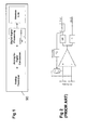
- FIG. 1 shows a blockdiagram of an example of a portable biomedical device (90) for processing biopotential signals, e.g. electrocardiogram (ECG) signals.
- ECG electrocardiogram
- ADC analog to digital conversion
- DSP digital signal processor
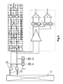
- a typical ECG signal to be measured is shown in Figure 3 . It consists of a P wave, a QRS complex and a T wave. Among these three signals, the QRS complex has the highest frequency, while the rest of the signal has low frequencies.
- the ECG signal has a frequency spectrum typically located between 0.1 Hz and 250 Hz. As used herein, 250 Hz is the "expected maximum frequency" of a typical ECG signal. Other biopotential signals may however have another expected maximum frequency.
- Figure 4 shows a block-diagram of part of an electronic medical device 90 for continuously and simultaneously measuring an impedance and a biopotential signal 4 on the skin of a biological subject 13. It comprises a current source 11 for generating a predetermined alternating current 12 having a first frequency, output terminals 51 for applying the alternating current 12 to electrodes 31 on the skin 13 for creating an alternating voltage signal, input terminals 52 for measuring an input signal 1 from electodes 32 on the skin 13, an impedance signal extraction block 49 for extracting an impedance signal 8 from said input signal 1, and a biopotential signal extraction block 48 for extracting a biopotential signal 4 from the input signal 1.
- a current source 11 for generating a predetermined alternating current 12 having a first frequency
- output terminals 51 for applying the alternating current 12 to electrodes 31 on the skin 13 for creating an alternating voltage signal
- input terminals 52 for measuring an input signal 1 from electodes 32 on the skin 13
- an impedance signal extraction block 49 for extracting an impedance signal 8 from said input
- the impedance signal extraction block 49 comprises a first instrumentation amplifier 41 connected to a first and second demodulator 43a, 43b for extracting a first and a second baseband impedance signal 8a, 8b, the first resp. second demodulator 43a, 43b using a first resp. third control signal 21, 23 both having a frequency equal to the first frequency.
- the third control signal 23 is 90° phase shifted with respect to the first control signal 21. In this way, real and imaginary parts of the impedance signal are demodulated simultaneously.
- the first frequency is chosen above a predetermined mimimum, which is selected for achieving spectral separation of the biopotential and impedance signals.
- the first frequency is preferably at least twice the expected maximum biopotential frequency, i.e. preferably at least 500 Hz for ECG.
- the electrodes 31 and 32 are placed on the skin.
- the measured impedance is from the input signal measured by means of the electrodes 32 is the impedance of the biological skin tissue between the electrodes.
- the impedance can be a complex value, having a real and an imaginary part, especially when the electrodes 31, 32 are moving.
- alternating current 12 prevents corrosion of the electrodes.
- the current is typically chosen smaller than 1 ⁇ A, or preferably even smaller than 100 nA, so that the alternating voltage amplitude is limited, e.g. to the same order of magnitude as the biopotential signal.
- the first frequency for measuring an ECG signal is e.g. 500Hz, but the invention will also work for higher or lower frequencies.
- the alternating current 12 can e.g. be a sine wave or a square wave, or any other waveform found suitable by the person skilled in the art.
- the first amplifier is preferably an instrumentation amplifier 41, meaning an amplifier that implements a certain perdefined multiplication for the input signal.
- two impedance signals 8a, 8b with a 90° phase shift are continuously extracted, so that an impedance amplitude can be calculated on a continuous basis.
- control signals 21, 23 can e.g. be sine waves or clock signals, or other signals.
- the current source 11 comprises a DC current generator 14 and a first chopper modulator 44 controlled by a first control signal 21 for generating the predetermined alternating current 12.
- the first and second demodulators 43a, 43b are chopper demodulators controlled by the first resp. third control signal 21, 23.
- Chopper modulation of a differential incoming signal can e.g. be implemented by a double switch which is either directly or inversely coupled to a differential output, whereby the control signal controls the state of the switch.
- the control signals typically are clock signals with a 50% duty cycle.
- the biopotential signal extraction block 48 comprises a second chopper modulator 45 connected to a second instrumentation amplifier 42, connected to a second chopper demodulator 47, both the modulator 45 and demodulator 47 being controlled by a second clock signal 22 having a second frequency, whereby the second frequency is the same as the first frequency.
- Chopper stabilization of the second instrumentation amplifier 42 offers the advantage of cancelling DC offset and reducing low frequency noise introduced by the second instrumentation amplifier 42.
- the chopper demodulator is followed by a programmable gain amplifier (PGA) before entering an ADC for matching the signal amplitude to the subsequent ADC input range.
- PGA programmable gain amplifier
- the terminals 52 and electrodes 32 for measuring the input signal 1 and the terminals 51 and electrodes 31 for applying the alternating current 12 are different terminals and electrodes.
- Other topologies are possible however, e.g. a single set of terminals 51 and electrodes 31 could be used, as shown in Fig 5 .
- movement artefact signals show a maximum correlation to both the impedance 8a, 8b and the biopotential signal 4.
- a single set of electrodes is also preferred by a patient.
- the impedance which is derived from the known (predetermined) current and the measured alternating voltage is the impedance of the electrodes 32, the impedance of the biological skin tissue between the electrodes 32 and the half-cell potential of the electrode-tissue interface.
- the impedance can be a complex value, having a real and an imaginary part, especially when the electrodes 32 are moving.
- the Analog Signal Processor comprises an ECG readout channel, two quadrature readout channels for continuous-time (CT) monitoring of electrode-tissue impedance, two quadrature readout channels for tracking power fluctuations in a specific frequency band, and an activity detector (AD) that can sense the frequency content (e.g. by determining the slope) of the ECG signal and comprises a SAR (successive approximation)-ADC.
- the ECG readout channel of the ASP uses a chopper stabilized instrumentation amplifier (lA) architecture for increasing common mode rejection ratio (CMRR) and reducing flicker noise (also called 1/f noise). This or a similar circuit can also be used for other biopotential signal measurements, not only for ECG signals.
- CMRR common mode rejection ratio
- flicker noise also called 1/f noise
- the current source 11 has means for adjusting the polarity of the modulated current 12 for measuring either a total impedance or an impedance difference.
- either the total impedance or the impedance difference between two electrodes can be characterized.
- the prior can be attractive for measuring the actual impedance of the electrodes for the continuous time electrode quality assessment, and the latter can be used to monitoring motion/movement artifacts.
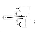
- Figure 7 shows the instrumentation amplifiers architecture used in Fig 6 , comprising two input stages (IS) connected to five output stages (OS).
- IS input stages
- OS output stages
- This way of using a single IS with multiple OS for implementing signal paths utilizing the same signal source but implementing different functionalities is enabled by using a current-balancing transconductance stage, similar to Ref. [1], as the IS.
- the replicas of OS can be connected to OUTP and OUTN in parallel, for instance with different demodulation clock frequencies. Since the demodulators are present at low-impedance nodes of the OS, the different clocking schemes of the OS have minimal affect to each other.
- the ASP includes quadrature readout channels similar to [2] with an adjustable demodulation frequency, f+ ⁇ , to shift the frequency of interest into the bandwidth of the switched-capacitor (SC) low-pass filters (LPF).
- SC switched-capacitor
- LPF low-pass filters
- the input stage of the presented lA consumes 1.2 ⁇ A from 2V, while achieving 86nV ⁇ Hz input referred noise density, whereas each OS consumes 400nA with negligible noise contribution. This translates into a noise-efficiency-factor (NEF) [4] of 4.7.
- NEF noise-efficiency-factor
- Ambulatory monitoring of ECG signals can be compromised by motion artifacts. It has been shown that the change of electrode-tissue impedance may be used to monitor the presence of such motion artifacts [5]. However, challenge arises from the requirement of measuring the impedance without affecting the ECG signal in a low-power manner.
- the electrode-tissue interface is stimulated with two AC currents at frequency, f(0°), being equal to 1 kHz. Any DC component of this stimulation current aggravates the motion artifact signal.
- the AC current sources incorporate chopper-stabilization at twice the frequency of the AC currents to set the mean value of the stimulation current to zero.
- the resulting AC voltage over the electrode-tissue interface is only demodulated by the continuous time (CT) impedance monitoring channels.
- CT continuous time
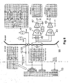
- Figure 9 shows the measured results from the ASP implemented in a standard 0.5 ⁇ m CMOS process.
- the top plot shows the acquired ECG signal.
- the Activity Detection block successfully detects the high frequency content of QRS complex and the steep edges of the motion artifact signals.
- the in-phase (l) and quadrature (Q) band-power extraction channels monitor the signal activity in a selected frequency band (13.7 Hz-18.3 Hz) for the detection of the QRS complex.
- the measurement ( Fig 9 third graph) shows the sum-of-squares of quadrature channels, clearly indicating a significant power fluctuation during the presence of a QRS complex, as well as, during the presence of motion artifact signals.
- the incorporated impedance measurement channels ( Fig 9 bottom graph) present a significant change in the electrode-tissue impedance clearly differentiating between a QRS complex (B regions) and motion artifacts (A regions). This shows that the measured impedance can be used as a good indicator of motion artifacts in the measured biopotential signal ( Fig 9 top graph), thereby improving the robustness of signal analysis against motion artifacts.
Landscapes
- Health & Medical Sciences (AREA)
- Life Sciences & Earth Sciences (AREA)
- Engineering & Computer Science (AREA)
- General Health & Medical Sciences (AREA)
- Veterinary Medicine (AREA)
- Biophysics (AREA)
- Biomedical Technology (AREA)
- Heart & Thoracic Surgery (AREA)
- Medical Informatics (AREA)
- Molecular Biology (AREA)
- Surgery (AREA)
- Animal Behavior & Ethology (AREA)
- Physics & Mathematics (AREA)
- Public Health (AREA)
- Pathology (AREA)
- Cardiology (AREA)
- Signal Processing (AREA)
- Power Engineering (AREA)
- Artificial Intelligence (AREA)
- Computer Vision & Pattern Recognition (AREA)
- Physiology (AREA)
- Psychiatry (AREA)
- Dermatology (AREA)
- Nuclear Medicine, Radiotherapy & Molecular Imaging (AREA)
- Radiology & Medical Imaging (AREA)
- Measurement And Recording Of Electrical Phenomena And Electrical Characteristics Of The Living Body (AREA)
Claims (11)
- Verfahren zum kontinuierlichen und simultanen Messen eines Impedanzsignals (8a, 8b) und eines Biopotentialsignals (4) auf der Haut (13) eines biologischen Gegenstands, wobei das Verfahren die folgenden Schritte umfasst:- Befestigen von Eingangs- und Ausgangselektroden (31, 32) an der Haut des biologischen Gegenstands;- Anlegen eines vorbestimmten Wechselstroms (12), der eine erste Frequenz aufweist, an die Ausgangselektroden (31, 32) zum Erzeugen eines Wechselspannungssignals über die Eingangselektroden (32), wobei die erste Frequenz mindestens eine vorbestimmte Minimalfrequenz ist;- Messen eines Eingangssignals (1) von den Eingangselektroden, wobei das Eingangssignal (1) ein Biopotentialsignal und das Wechselspannungssignal umfasst;- Extrahieren des Biopotentialsignals (4) aus dem Eingangssignal (1);- Extrahieren des Wechselspannungssignals aus dem Eingangssignal (1) und Bestimmen des Impedanzsignals (8a, 8b) von dem Wechselspannungssignal;
dadurch gekennzeichnet, dass:- der vorbestimmte Wechselstrom (12) durch Chopper-Modulation eines vorbestimmten Gleichstroms bei der ersten Frequenz erzeugt wird;- das Wechselspannungssignal durch Verstärken und Chopper-Demodulation des Eingangssignals (1) unter Verwendung eines Steuersignals (21, 23) extrahiert wird, das eine Frequenz aufweist, die gleich der ersten Frequenz ist;- wobei das Biopotentialsignal (4) von dem Eingangssignal (1) durch aufeinanderfolgende Chopper-Modulation, Verstärkung und Chopper-Demodulation des Eingangssignals (4) bei der ersten Frequenz extrahiert wird. - Verfahren nach Anspruch 1, dadurch gekennzeichnet, dass der Schritt des Extrahierens des Wechselspannungssignals das parallele Extrahieren eines ersten und eines zweiten Basisband-Spannungssignals (8a, 8b) umfasst, die für reelle und imaginäre Komponenten des Impedanzsignals charakteristisch sind.
- Verfahren nach Anspruch 2, dadurch gekennzeichnet, dass das erste und das zweite Basisband-Spannungssignal (8a, 8b) durch Demodulieren des Eingangssignals (1) unter Verwendung von zwei Steuersignalen (21, 23) erhalten werden, die eine Frequenz aufweisen, die gleich der ersten Frequenz ist, aber um 90° zueinander phasenverschoben sind.
- Verfahren nach einem der vorhergehenden Ansprüche, dadurch gekennzeichnet, dass das Biopotentialsignal (4) ein ECG- oder ein EEG-Signal ist.
- Verfahren nach einem der vorhergehenden Ansprüche, dadurch gekennzeichnet, dass die Schritte des Anlegens des Wechselstroms (12) und des Messens des Eingangssignals (1) durch einen einzigen Satz von Eingangs/Ausgangselektroden (31, 32) erfolgen.
- Verfahren nach einem der vorhergehenden Ansprüche, dadurch gekennzeichnet, dass die vorbestimmte Minimalfrequenz mindestens dem Zweifachen einer erwarteten Maximalfrequenz des Biopotentialsignals entspricht.
- Verfahren nach einem der vorhergehenden Ansprüche, das ferner den Schritt des Verwendens des Impedanzsignals zum Entfernen von Bewegungsartefakten von dem Biopotentialsignal umfasst.
- Elektronisches medizinisches Gerät (90) zum kontinuierlichen und simultanen Messen eines Impedanzsignals und eines Biopotentialsignals (4) auf der Haut (13) eines biologischen Gegenstands, wobei das elektronische medizinische Gerät Folgendes umfasst:- Eingangs- und Ausgangselektroden (31, 32), die bereitgestellt sind, um an der Haut des biologischen Gegenstands befestigt zu werden und mit Eingangs- und Ausgangsanschlüssen (51, 52) des Geräts (90) verbunden zu werden;- eine Stromquelle (11), die mit den Ausgangsanschlüssen (51) verbunden ist, um einen vorbestimmten Wechselstrom (12) zu erzeugen, der eine erste Frequenz über einer vorbestimmten Minimalfrequenz aufweist, die an die Ausgangselektroden (31, 32) angelegt wird, um ein Wechselspannungssignal über die Eingangselektroden (32) zu erzeugen;- einen Impedanzsignal-Extraktionsblock (49) der mit den Eingangsanschlüssen (52) verbunden ist, um das Wechselspannungssignal (8) aus einem Eingangssignal (1) zu extrahieren, das an den Eingangselektroden gemessen wird, und das Impedanzsignal (8a, 8b) von dem Wechselspannungssignal zu bestimmen;- einen Biopotentialsignal-Extraktionsblock (48), der mit den Eingangsanschlüssen (52) verbunden ist, um das Biopotentialsignal (4) von dem Eingangssignal (1) zu extrahieren;
dadurch gekennzeichnet, dass:- die Stromquelle (11) einen Gleichstromgenerator (14) und einen ersten Chopper-Modulator (44) zum Erzeugen des vorbestimmten Wechselstroms (12) umfasst;- der Impedanzsignal-Extraktionsblock (49) einen ersten Verstärker (41), der mit den Eingangsanschlüssen (52) verbunden ist, um das Eingangssignal (1) zu verstärken, und einen Chopper-Demodulationsblock (43a, 43b) umfasst, der mit dem ersten Verstärker zur Chopper-Demodulation des Eingangssignals (1) unter Verwendung eines Steuersignals verbunden ist, das eine Frequenz aufweist, die gleich der ersten Frequenz ist;- der Biopotentialsignal-Extraktionsblock (48) nacheinander einen zweiten Chopper-Modulator (45), einen zweiten Verstärker (42) und einen dritten Chopper-Demodulator (47) umfasst, wobei der zweite Modulator (45) und der dritte Demodulator (47) durch ein Taktsignal (22) gesteuert werden, das eine zweite Frequenz aufweist, wobei die zweite Frequenz dieselbe wie die erste Frequenz ist. - Elektronische medizinische Vorrichtung (90) nach Anspruch 8, dadurch gekennzeichnet, dass der Chopper-Demodulationsblock einen ersten und einen zweiten Chopper-Demodulationsblock (43a, 43b) umfasst, die zwei Steuersignale (21, 23) verwenden, die eine Frequenz aufweisen, die gleich der ersten Frequenz ist, aber in Bezug zueinander um 90° phasenverschoben shd, um ein erstes und ein zweites Basisband-Spannungssignal (8a, 8b) zu extrahieren, das für reelle und imaginäre Komponenten des Impedanzsignals charakteristisch ist.
- Elektronisches medizinisches Gerät (90) nach Anspruch 8 oder 9, dadurch gekennzeichnet, dass Eingangs- und Ausgangselektroden durch einen einzigen Satz von Eingangs/Ausgangselektroden (31, 32) gebildet sind, die mit einem einzigen Satz von Eingangs/Ausgangsanschlüssen (51, 52) verbunden sind.
- Elektronisches medizinisches Gerät (90) nach einem der Ansprüche 8 bis 10, dadurch gekennzeichnet, dass die Stromquelle (11) Mittel zum Einstellen der Polarität des modulierten Stroms (12) zum Messen von entweder einer Gesamtimpedanz oder einer Impedanzdifferenz aufweist.
Priority Applications (3)
| Application Number | Priority Date | Filing Date | Title |
|---|---|---|---|
| US12/882,120 US8862210B2 (en) | 2009-09-14 | 2010-09-14 | Analogue signal processors |
| US12/882,126 US8454505B2 (en) | 2009-09-14 | 2010-09-14 | Method and electronic medical device for simultaneously measuring an impedance and a biopotential signal |
| EP10176687.1A EP2298164B1 (de) | 2009-09-14 | 2010-09-14 | Vorrichtung zur kardialen Überwachung mit adaptiven Probenentnahme |
Applications Claiming Priority (1)
| Application Number | Priority Date | Filing Date | Title |
|---|---|---|---|
| US24229909P | 2009-09-14 | 2009-09-14 |
Publications (3)
| Publication Number | Publication Date |
|---|---|
| EP2294979A1 EP2294979A1 (de) | 2011-03-16 |
| EP2294979A8 EP2294979A8 (de) | 2011-09-14 |
| EP2294979B1 true EP2294979B1 (de) | 2013-12-18 |
Family
ID=42244455
Family Applications (1)
| Application Number | Title | Priority Date | Filing Date |
|---|---|---|---|
| EP10152299.3A Active EP2294979B1 (de) | 2009-09-14 | 2010-02-01 | Verfahren und elektronisches medizinisches Gerät für simultane Messung sowie Impedanz und Biopotenzialsignal |
Country Status (2)
| Country | Link |
|---|---|
| US (1) | US8454505B2 (de) |
| EP (1) | EP2294979B1 (de) |
Families Citing this family (38)
| Publication number | Priority date | Publication date | Assignee | Title |
|---|---|---|---|---|
| US9839368B2 (en) * | 2012-01-17 | 2017-12-12 | Zoll Medical Corporation | Systems and methods for filtering ECG artifacts |
| WO2014021883A1 (en) * | 2012-08-01 | 2014-02-06 | Draeger Medical Systems, Inc. | System and method for measuring contact impedance of an electrode |
| US9633577B2 (en) | 2012-10-02 | 2017-04-25 | Zoll Medical Corporation | CPR training system and methods |
| ES2776178T3 (es) | 2012-10-24 | 2020-07-29 | Dreamscape Medical Llc | Sistemas para detectar bio-señales basadas en el cerebro |
| US9351653B1 (en) * | 2012-11-29 | 2016-05-31 | Intan Technologies, LLC | Multi-channel reconfigurable systems and methods for sensing biopotential signals |
| US10039460B2 (en) | 2013-01-22 | 2018-08-07 | MiSleeping, Inc. | Neural activity recording apparatus and method of using same |
| SG11201510134YA (en) * | 2013-06-12 | 2016-01-28 | Agency Science Tech & Res | Real-time multi-functional ecg signal processing system, dspe for the ecg signal processing system, and method thereof |
| KR102255204B1 (ko) * | 2013-08-28 | 2021-05-24 | 삼성전자주식회사 | 재구성 가능한 측정 장치 및 그 장치를 제어하는 방법 |
| US9456763B2 (en) * | 2013-09-11 | 2016-10-04 | Medtronic, Inc. | Apparatus and method for simultaneous capture of biopotential and tissue impedance signals |
| EP3072266B1 (de) | 2013-11-19 | 2019-01-09 | The Regents of The University of California | Sättigungstolerante elektrophysikalische aufnahmeschnittstelle |
| DE102013022090A1 (de) | 2013-12-16 | 2015-06-18 | Seca Ag | Multifunktionsmessvorrichtung und Verfahren zur Ermittlung und Auswertung verschiedener Messsignale eines biologischen Subjektes |
| US10321838B2 (en) | 2014-01-07 | 2019-06-18 | Koninklijke Philips N.V. | Active low impedance electrode |
| KR101937676B1 (ko) | 2014-01-13 | 2019-01-14 | 삼성전자주식회사 | 생체 신호 증폭 회로 |
| KR101987408B1 (ko) | 2014-01-21 | 2019-06-11 | 삼성전자주식회사 | 생체 임피던스 측정 장치 및 방법 |
| KR102198953B1 (ko) | 2014-03-12 | 2021-01-05 | 삼성전자주식회사 | 병렬 생체 신호 프로세서 및 병렬 생체 신호 프로세서의 제어 방법 |
| US10149628B2 (en) | 2014-05-20 | 2018-12-11 | Samsung Electronics Co., Ltd. | Signal processing method and apparatus |
| KR102170751B1 (ko) | 2014-07-02 | 2020-10-27 | 삼성전자주식회사 | 신호 처리 장치 및 방법 |
| KR102399562B1 (ko) * | 2014-07-28 | 2022-05-18 | 삼성전자주식회사 | 신호 처리 장치 및 방법, 생체 신호 처리 장치 및 방법 |
| US9594104B2 (en) * | 2014-10-22 | 2017-03-14 | Natus Medical Incorporated | Simultaneous impedance testing method and apparatus |
| KR102299862B1 (ko) * | 2014-12-23 | 2021-09-08 | 삼성전자주식회사 | 신호 처리 장치 및 방법 |
| KR20170009034A (ko) | 2015-07-15 | 2017-01-25 | 클레어픽셀 주식회사 | 공통모드 제거비가 개선된 생체 신호 검출용 증폭 장치 |
| US11096629B2 (en) * | 2015-09-14 | 2021-08-24 | Stichting Imec Nederland | Bio-impedance spectroscopy system and method for bio-impedance measurement |
| US10368805B2 (en) | 2016-12-29 | 2019-08-06 | Drägerwerk AG & Co. KGaA | Electrode impedance measurement |
| WO2018194093A1 (ja) * | 2017-04-19 | 2018-10-25 | 学校法人関西大学 | 生体情報の推定装置 |
| CN110650681B (zh) * | 2017-05-15 | 2023-08-15 | 布鲁姆技术公司 | 用于监测胎儿健康的系统和方法 |
| KR102463174B1 (ko) | 2017-07-31 | 2022-11-04 | 삼성전자주식회사 | 재설정 가능한 증폭기 및 그 증폭 방법 |
| EP3488767B1 (de) * | 2017-11-24 | 2026-04-15 | Nokia Technologies Oy | Biosignaldetektion |
| CN110353663A (zh) * | 2019-07-10 | 2019-10-22 | 刘阳 | 一种心电信号获取系统及方法 |
| TWI752867B (zh) * | 2020-04-24 | 2022-01-11 | 聯發科技股份有限公司 | 生物電勢採集系統的電路 |
| DK180663B1 (en) * | 2020-04-27 | 2021-11-11 | Paragit Solutions Aps | Apparatus and method for detection of biopotential signals |
| EP3928692A1 (de) | 2020-06-26 | 2021-12-29 | CSEM Centre Suisse d'Electronique et de Microtechnique SA - Recherche et Développement | Sensorvorrichtung für potenzial- und impedanzmessungen |
| US11986306B2 (en) * | 2020-09-09 | 2024-05-21 | Mediatek Inc. | Direct sampling electrode-tissue impedance system and associated signal processing method |
| CN112472094B (zh) * | 2020-12-14 | 2024-08-13 | 南京伟思医疗科技股份有限公司 | 一种用于生物电信号的高耐压仪表放大器 |
| CN115336996A (zh) * | 2021-04-27 | 2022-11-15 | 深圳市理邦精密仪器股份有限公司 | 一种脑电阻抗测量系统及脑电阻抗的测量方法 |
| CN115005842B (zh) * | 2022-08-09 | 2022-11-15 | 之江实验室 | 一种频率调制的脑机接口芯片输入阻抗增强方法及系统 |
| CN116965833A (zh) * | 2023-08-30 | 2023-10-31 | 深圳迈瑞动物医疗科技股份有限公司 | 移动监护设备、移动监护方法及可读存储介质 |
| WO2025115689A1 (ja) * | 2023-11-29 | 2025-06-05 | 旭化成エレクトロニクス株式会社 | 生体情報測定装置及び生体情報測定方法 |
| CN120148745B (zh) * | 2025-02-21 | 2025-12-26 | 北京领创医谷科技发展有限责任公司 | 推荐电极刺激频率的方法和装置 |
Family Cites Families (20)
| Publication number | Priority date | Publication date | Assignee | Title |
|---|---|---|---|---|
| US729168A (en) * | 1902-08-06 | 1903-05-26 | Henry T Henderson | Ball-coupling. |
| US3667056A (en) | 1970-11-17 | 1972-05-30 | Instrumentation Specialties Co | Sample, hold, and subtract circuit |
| US4610254A (en) * | 1984-03-08 | 1986-09-09 | Physio-Control Corporation | Interactive portable defibrillator |
| DE3509118C2 (de) | 1985-03-14 | 1994-03-24 | Bosch Gmbh Robert | Verfahren und Vorrichtung zur Messung des Durchsatzes eines ein Rohr durchströmenden Mediums |
| US5020541A (en) * | 1988-07-13 | 1991-06-04 | Physio-Control Corporation | Apparatus for sensing lead and transthoracic impedances |
| US5197479A (en) * | 1991-05-13 | 1993-03-30 | Mortara Instrument | Automatic electrode channel impedance measurement system for egg monitor |
| US5263486A (en) | 1991-11-01 | 1993-11-23 | Telectronics Pacing Systems, Inc. | Apparatus and method for electrocardiogram data compression |
| US5381803A (en) | 1993-03-12 | 1995-01-17 | Hewlett-Packard Corporation | QRS detector for defibrillator/monitor |
| US5836982A (en) | 1997-02-19 | 1998-11-17 | Medtronic, Inc. | System and method of data compression and non-linear sampling for implantable and battery-powered devices |
| JP2001198098A (ja) * | 2000-01-21 | 2001-07-24 | Tanita Corp | むくみ測定方法及びむくみ測定装置 |
| US6821254B2 (en) * | 2000-07-21 | 2004-11-23 | Institute Of Critical Care Medicine | Cardiac/respiratory arrest detector |
| BR0210833A (pt) * | 2001-07-06 | 2004-06-22 | Aspect Medical Systems Inc | Sistema e método para a medição de impedância bioelétrica na presença de interferência |
| EE04767B1 (et) * | 2002-12-06 | 2007-02-15 | Tallinna Tehnika�likool | Meetod ja seade elektrilise bioimpedantsi mõõtmiseks |
| AU2003902187A0 (en) | 2003-05-08 | 2003-05-22 | Aimedics Pty Ltd | Patient monitor |
| US8068905B2 (en) * | 2004-02-26 | 2011-11-29 | Compumedics Limited | Method and apparatus for continuous electrode impedance monitoring |
| ATE383106T1 (de) * | 2005-08-17 | 2008-01-15 | Osypka Medical Gmbh | Digitale demodulationsvorrichtung und -verfahren zur messung der elektrischen bioimpedanz oder bioadmittanz |
| US8553808B2 (en) | 2006-12-13 | 2013-10-08 | Motorola Mobility Llc | Method and apparatus for detecting the presence of a signal in a frequency band using non-uniform sampling |
| US7391257B1 (en) | 2007-01-31 | 2008-06-24 | Medtronic, Inc. | Chopper-stabilized instrumentation amplifier for impedance measurement |
| EP2309644B1 (de) | 2008-01-31 | 2015-09-02 | Imec | Steuerschaltung mit einer hohen Zeitkonstante |
| US20100324404A1 (en) * | 2009-06-22 | 2010-12-23 | Analogic Corporation | Icg/ecg monitoring apparatus |
-
2010
- 2010-02-01 EP EP10152299.3A patent/EP2294979B1/de active Active
- 2010-09-14 US US12/882,126 patent/US8454505B2/en active Active
Non-Patent Citations (1)
| Title |
|---|
| AL-THADDEUS AVESTRUZ ET AL: "A 5 W/Channel Spectral Analysis IC for Chronic Bidirectional Brainâ Machine Interfaces", IEEE JOURNAL OF SOLID-STATE CIRCUITS, IEEE SERVICE CENTER, PISCATAWAY, NJ, USA, vol. 43, no. 12, 1 December 2008 (2008-12-01), pages 3006 - 3024, XP011238677, ISSN: 0018-9200, DOI: 10.1109/JSSC.2008.2006460 * |
Also Published As
| Publication number | Publication date |
|---|---|
| EP2294979A8 (de) | 2011-09-14 |
| US8454505B2 (en) | 2013-06-04 |
| US20110066054A1 (en) | 2011-03-17 |
| EP2294979A1 (de) | 2011-03-16 |
Similar Documents
| Publication | Publication Date | Title |
|---|---|---|
| EP2294979B1 (de) | Verfahren und elektronisches medizinisches Gerät für simultane Messung sowie Impedanz und Biopotenzialsignal | |
| Yazicioglu et al. | A 30$\mu $ w analog signal processor ASIC for portable biopotential signal monitoring | |
| US8862210B2 (en) | Analogue signal processors | |
| US8755868B2 (en) | Adaptive sampling | |
| Buxi et al. | Correlation between electrode-tissue impedance and motion artifact in biopotential recordings | |
| EP2843833B1 (de) | Rekonfigurierbare Messvorrichtung und Verfahren zur Steuerung der Vorrichtung | |
| US8914099B2 (en) | Biomedical acquisition system with motion artifact reduction | |
| TWI481196B (zh) | 生物電信號感測儀器與其基線漂移移除裝置 | |
| KR100825888B1 (ko) | 전극 동잡음 보상 회로 및 전극 동잡음 보상 방법 | |
| EP3141898A1 (de) | Bioimpedanzspektroskopiesystem und verfahren für bioimpedanzmessung | |
| Yazicioglu et al. | A 30µW Analog Signal Processor ASIC for biomedical signal monitoring | |
| CN110840454B (zh) | 一种脑电信号采集装置和方法 | |
| Kim et al. | A 2.4 µA continuous-time electrode-skin impedance measurement circuit for motion artifact monitoring in ECG acquisition systems | |
| CN101902958A (zh) | 无接触生物电势传感器 | |
| CN107788983A (zh) | 用于确定生物组织的生物阻抗的同步检测电路和方法 | |
| EP3949833B1 (de) | Kontaktzustandsdetektor und am körper tragbare vorrichtung | |
| US20180067154A1 (en) | Synchronous Detection Circuit And Method For Extracting Magnitude And Phase From A Waveform | |
| CN214434253U (zh) | 一种上肢康复穿戴式设备及系统 | |
| EP3667907B1 (de) | Ausleseschaltung zum erfassen eines mehrkanaligen biopotentialsignals und sensor zum erfassen eines biopotentialsignals | |
| DongseoUniversity | The deployment of novel techniques for mobile ECG monitoring | |
| Qu et al. | A 44μW Two-Electrode ECG Acquisition ASIC with Hybrid Motion Artifact Removal and Power-Efficient R-Peak Detection | |
| Tomasini et al. | Digitally controlled feedback for DC offset cancellation in a wearable multichannel EMG platform | |
| CN205338943U (zh) | 无线远程心电监测系统 | |
| US20240122547A1 (en) | Human body signal collection apparatus | |
| KR102478292B1 (ko) | 반복적으로 고주파 전류를 주입하거나 전압을 인가하는 동안에 저주파 생체신호를 측정하는 장치 및 그 방법 |
Legal Events
| Date | Code | Title | Description |
|---|---|---|---|
| PUAI | Public reference made under article 153(3) epc to a published international application that has entered the european phase |
Free format text: ORIGINAL CODE: 0009012 |
|
| 17P | Request for examination filed |
Effective date: 20101223 |
|
| AK | Designated contracting states |
Kind code of ref document: A1 Designated state(s): AT BE BG CH CY CZ DE DK EE ES FI FR GB GR HR HU IE IS IT LI LT LU LV MC MK MT NL NO PL PT RO SE SI SK SM TR |
|
| AX | Request for extension of the european patent |
Extension state: AL BA RS |
|
| RTI1 | Title (correction) |
Free format text: METHOD AND ELECTRONIC MEDICAL DEVICE FOR SIMULTANEOUSLY MEASURING AN IMPEDANCE AND A BIOPOTENTIAL SIGNAL |
|
| RTI1 | Title (correction) |
Free format text: METHOD AND ELECTRONIC MEDICAL DEVICE FOR SIMULTANEOUSLY MEASURING AN IMPEDANCE AND A BIOPOTENTIAL SIGNAL |
|
| 17Q | First examination report despatched |
Effective date: 20110503 |
|
| GRAP | Despatch of communication of intention to grant a patent |
Free format text: ORIGINAL CODE: EPIDOSNIGR1 |
|
| INTG | Intention to grant announced |
Effective date: 20130806 |
|
| GRAS | Grant fee paid |
Free format text: ORIGINAL CODE: EPIDOSNIGR3 |
|
| GRAA | (expected) grant |
Free format text: ORIGINAL CODE: 0009210 |
|
| AK | Designated contracting states |
Kind code of ref document: B1 Designated state(s): AT BE BG CH CY CZ DE DK EE ES FI FR GB GR HR HU IE IS IT LI LT LU LV MC MK MT NL NO PL PT RO SE SI SK SM TR |
|
| REG | Reference to a national code |
Ref country code: GB Ref legal event code: FG4D |
|
| REG | Reference to a national code |
Ref country code: CH Ref legal event code: EP |
|
| REG | Reference to a national code |
Ref country code: AT Ref legal event code: REF Ref document number: 645198 Country of ref document: AT Kind code of ref document: T Effective date: 20140115 |
|
| REG | Reference to a national code |
Ref country code: IE Ref legal event code: FG4D |
|
| REG | Reference to a national code |
Ref country code: DE Ref legal event code: R096 Ref document number: 602010012470 Country of ref document: DE Effective date: 20140213 |
|
| REG | Reference to a national code |
Ref country code: NL Ref legal event code: VDEP Effective date: 20131218 |
|
| PG25 | Lapsed in a contracting state [announced via postgrant information from national office to epo] |
Ref country code: SE Free format text: LAPSE BECAUSE OF FAILURE TO SUBMIT A TRANSLATION OF THE DESCRIPTION OR TO PAY THE FEE WITHIN THE PRESCRIBED TIME-LIMIT Effective date: 20131218 Ref country code: HR Free format text: LAPSE BECAUSE OF FAILURE TO SUBMIT A TRANSLATION OF THE DESCRIPTION OR TO PAY THE FEE WITHIN THE PRESCRIBED TIME-LIMIT Effective date: 20131218 Ref country code: FI Free format text: LAPSE BECAUSE OF FAILURE TO SUBMIT A TRANSLATION OF THE DESCRIPTION OR TO PAY THE FEE WITHIN THE PRESCRIBED TIME-LIMIT Effective date: 20131218 Ref country code: LT Free format text: LAPSE BECAUSE OF FAILURE TO SUBMIT A TRANSLATION OF THE DESCRIPTION OR TO PAY THE FEE WITHIN THE PRESCRIBED TIME-LIMIT Effective date: 20131218 Ref country code: NO Free format text: LAPSE BECAUSE OF FAILURE TO SUBMIT A TRANSLATION OF THE DESCRIPTION OR TO PAY THE FEE WITHIN THE PRESCRIBED TIME-LIMIT Effective date: 20140318 |
|
| REG | Reference to a national code |
Ref country code: AT Ref legal event code: MK05 Ref document number: 645198 Country of ref document: AT Kind code of ref document: T Effective date: 20131218 |
|
| REG | Reference to a national code |
Ref country code: LT Ref legal event code: MG4D |
|
| PG25 | Lapsed in a contracting state [announced via postgrant information from national office to epo] |
Ref country code: LV Free format text: LAPSE BECAUSE OF FAILURE TO SUBMIT A TRANSLATION OF THE DESCRIPTION OR TO PAY THE FEE WITHIN THE PRESCRIBED TIME-LIMIT Effective date: 20131218 |
|
| PG25 | Lapsed in a contracting state [announced via postgrant information from national office to epo] |
Ref country code: BE Free format text: LAPSE BECAUSE OF FAILURE TO SUBMIT A TRANSLATION OF THE DESCRIPTION OR TO PAY THE FEE WITHIN THE PRESCRIBED TIME-LIMIT Effective date: 20131218 Ref country code: IS Free format text: LAPSE BECAUSE OF FAILURE TO SUBMIT A TRANSLATION OF THE DESCRIPTION OR TO PAY THE FEE WITHIN THE PRESCRIBED TIME-LIMIT Effective date: 20140418 Ref country code: EE Free format text: LAPSE BECAUSE OF FAILURE TO SUBMIT A TRANSLATION OF THE DESCRIPTION OR TO PAY THE FEE WITHIN THE PRESCRIBED TIME-LIMIT Effective date: 20131218 |
|
| PG25 | Lapsed in a contracting state [announced via postgrant information from national office to epo] |
Ref country code: NL Free format text: LAPSE BECAUSE OF FAILURE TO SUBMIT A TRANSLATION OF THE DESCRIPTION OR TO PAY THE FEE WITHIN THE PRESCRIBED TIME-LIMIT Effective date: 20131218 Ref country code: RO Free format text: LAPSE BECAUSE OF FAILURE TO SUBMIT A TRANSLATION OF THE DESCRIPTION OR TO PAY THE FEE WITHIN THE PRESCRIBED TIME-LIMIT Effective date: 20131218 Ref country code: CY Free format text: LAPSE BECAUSE OF FAILURE TO SUBMIT A TRANSLATION OF THE DESCRIPTION OR TO PAY THE FEE WITHIN THE PRESCRIBED TIME-LIMIT Effective date: 20131218 Ref country code: PL Free format text: LAPSE BECAUSE OF FAILURE TO SUBMIT A TRANSLATION OF THE DESCRIPTION OR TO PAY THE FEE WITHIN THE PRESCRIBED TIME-LIMIT Effective date: 20131218 Ref country code: CZ Free format text: LAPSE BECAUSE OF FAILURE TO SUBMIT A TRANSLATION OF THE DESCRIPTION OR TO PAY THE FEE WITHIN THE PRESCRIBED TIME-LIMIT Effective date: 20131218 Ref country code: SK Free format text: LAPSE BECAUSE OF FAILURE TO SUBMIT A TRANSLATION OF THE DESCRIPTION OR TO PAY THE FEE WITHIN THE PRESCRIBED TIME-LIMIT Effective date: 20131218 Ref country code: ES Free format text: LAPSE BECAUSE OF FAILURE TO SUBMIT A TRANSLATION OF THE DESCRIPTION OR TO PAY THE FEE WITHIN THE PRESCRIBED TIME-LIMIT Effective date: 20131218 Ref country code: PT Free format text: LAPSE BECAUSE OF FAILURE TO SUBMIT A TRANSLATION OF THE DESCRIPTION OR TO PAY THE FEE WITHIN THE PRESCRIBED TIME-LIMIT Effective date: 20140418 Ref country code: AT Free format text: LAPSE BECAUSE OF FAILURE TO SUBMIT A TRANSLATION OF THE DESCRIPTION OR TO PAY THE FEE WITHIN THE PRESCRIBED TIME-LIMIT Effective date: 20131218 |
|
| REG | Reference to a national code |
Ref country code: DE Ref legal event code: R097 Ref document number: 602010012470 Country of ref document: DE |
|
| PG25 | Lapsed in a contracting state [announced via postgrant information from national office to epo] |
Ref country code: LU Free format text: LAPSE BECAUSE OF FAILURE TO SUBMIT A TRANSLATION OF THE DESCRIPTION OR TO PAY THE FEE WITHIN THE PRESCRIBED TIME-LIMIT Effective date: 20140201 Ref country code: MC Free format text: LAPSE BECAUSE OF FAILURE TO SUBMIT A TRANSLATION OF THE DESCRIPTION OR TO PAY THE FEE WITHIN THE PRESCRIBED TIME-LIMIT Effective date: 20131218 |
|
| REG | Reference to a national code |
Ref country code: CH Ref legal event code: PL |
|
| PLBE | No opposition filed within time limit |
Free format text: ORIGINAL CODE: 0009261 |
|
| STAA | Information on the status of an ep patent application or granted ep patent |
Free format text: STATUS: NO OPPOSITION FILED WITHIN TIME LIMIT |
|
| PG25 | Lapsed in a contracting state [announced via postgrant information from national office to epo] |
Ref country code: LI Free format text: LAPSE BECAUSE OF NON-PAYMENT OF DUE FEES Effective date: 20140228 Ref country code: DK Free format text: LAPSE BECAUSE OF FAILURE TO SUBMIT A TRANSLATION OF THE DESCRIPTION OR TO PAY THE FEE WITHIN THE PRESCRIBED TIME-LIMIT Effective date: 20131218 Ref country code: CH Free format text: LAPSE BECAUSE OF NON-PAYMENT OF DUE FEES Effective date: 20140228 |
|
| 26N | No opposition filed |
Effective date: 20140919 |
|
| REG | Reference to a national code |
Ref country code: IE Ref legal event code: MM4A |
|
| REG | Reference to a national code |
Ref country code: DE Ref legal event code: R097 Ref document number: 602010012470 Country of ref document: DE Effective date: 20140919 |
|
| PG25 | Lapsed in a contracting state [announced via postgrant information from national office to epo] |
Ref country code: IE Free format text: LAPSE BECAUSE OF NON-PAYMENT OF DUE FEES Effective date: 20140201 |
|
| PG25 | Lapsed in a contracting state [announced via postgrant information from national office to epo] |
Ref country code: SI Free format text: LAPSE BECAUSE OF FAILURE TO SUBMIT A TRANSLATION OF THE DESCRIPTION OR TO PAY THE FEE WITHIN THE PRESCRIBED TIME-LIMIT Effective date: 20131218 |
|
| REG | Reference to a national code |
Ref country code: FR Ref legal event code: PLFP Year of fee payment: 7 |
|
| PG25 | Lapsed in a contracting state [announced via postgrant information from national office to epo] |
Ref country code: MT Free format text: LAPSE BECAUSE OF FAILURE TO SUBMIT A TRANSLATION OF THE DESCRIPTION OR TO PAY THE FEE WITHIN THE PRESCRIBED TIME-LIMIT Effective date: 20131218 |
|
| PG25 | Lapsed in a contracting state [announced via postgrant information from national office to epo] |
Ref country code: SM Free format text: LAPSE BECAUSE OF FAILURE TO SUBMIT A TRANSLATION OF THE DESCRIPTION OR TO PAY THE FEE WITHIN THE PRESCRIBED TIME-LIMIT Effective date: 20131218 |
|
| PG25 | Lapsed in a contracting state [announced via postgrant information from national office to epo] |
Ref country code: IT Free format text: LAPSE BECAUSE OF FAILURE TO SUBMIT A TRANSLATION OF THE DESCRIPTION OR TO PAY THE FEE WITHIN THE PRESCRIBED TIME-LIMIT Effective date: 20131218 Ref country code: BG Free format text: LAPSE BECAUSE OF FAILURE TO SUBMIT A TRANSLATION OF THE DESCRIPTION OR TO PAY THE FEE WITHIN THE PRESCRIBED TIME-LIMIT Effective date: 20131218 Ref country code: GR Free format text: LAPSE BECAUSE OF FAILURE TO SUBMIT A TRANSLATION OF THE DESCRIPTION OR TO PAY THE FEE WITHIN THE PRESCRIBED TIME-LIMIT Effective date: 20140319 |
|
| PG25 | Lapsed in a contracting state [announced via postgrant information from national office to epo] |
Ref country code: HU Free format text: LAPSE BECAUSE OF FAILURE TO SUBMIT A TRANSLATION OF THE DESCRIPTION OR TO PAY THE FEE WITHIN THE PRESCRIBED TIME-LIMIT; INVALID AB INITIO Effective date: 20100201 Ref country code: TR Free format text: LAPSE BECAUSE OF FAILURE TO SUBMIT A TRANSLATION OF THE DESCRIPTION OR TO PAY THE FEE WITHIN THE PRESCRIBED TIME-LIMIT Effective date: 20131218 |
|
| REG | Reference to a national code |
Ref country code: FR Ref legal event code: PLFP Year of fee payment: 8 |
|
| REG | Reference to a national code |
Ref country code: FR Ref legal event code: PLFP Year of fee payment: 9 |
|
| PG25 | Lapsed in a contracting state [announced via postgrant information from national office to epo] |
Ref country code: MK Free format text: LAPSE BECAUSE OF FAILURE TO SUBMIT A TRANSLATION OF THE DESCRIPTION OR TO PAY THE FEE WITHIN THE PRESCRIBED TIME-LIMIT Effective date: 20131218 |
|
| P01 | Opt-out of the competence of the unified patent court (upc) registered |
Effective date: 20230513 |
|
| PGFP | Annual fee paid to national office [announced via postgrant information from national office to epo] |
Ref country code: GB Payment date: 20260121 Year of fee payment: 17 |
|
| PGFP | Annual fee paid to national office [announced via postgrant information from national office to epo] |
Ref country code: DE Payment date: 20260121 Year of fee payment: 17 |
|
| PGFP | Annual fee paid to national office [announced via postgrant information from national office to epo] |
Ref country code: FR Payment date: 20260121 Year of fee payment: 17 |