EP2295187A2 - Unité d'avance d'une fraise à capot destinée à fraiser la zone de soudure d'électrodes de soudure par point - Google Patents
Unité d'avance d'une fraise à capot destinée à fraiser la zone de soudure d'électrodes de soudure par point Download PDFInfo
- Publication number
- EP2295187A2 EP2295187A2 EP10176428A EP10176428A EP2295187A2 EP 2295187 A2 EP2295187 A2 EP 2295187A2 EP 10176428 A EP10176428 A EP 10176428A EP 10176428 A EP10176428 A EP 10176428A EP 2295187 A2 EP2295187 A2 EP 2295187A2
- Authority
- EP
- European Patent Office
- Prior art keywords
- feed
- pivotable
- cap cutter
- base
- arm
- Prior art date
- Legal status (The legal status is an assumption and is not a legal conclusion. Google has not performed a legal analysis and makes no representation as to the accuracy of the status listed.)
- Withdrawn
Links
- 238000003466 welding Methods 0.000 title claims abstract description 58
- 238000006073 displacement reaction Methods 0.000 claims abstract description 5
- 238000003801 milling Methods 0.000 claims description 19
- 230000000284 resting effect Effects 0.000 abstract 2
- 238000007792 addition Methods 0.000 description 3
- 238000004519 manufacturing process Methods 0.000 description 3
- XLOMVQKBTHCTTD-UHFFFAOYSA-N Zinc monoxide Chemical compound [Zn]=O XLOMVQKBTHCTTD-UHFFFAOYSA-N 0.000 description 2
- 230000001419 dependent effect Effects 0.000 description 2
- 230000003287 optical effect Effects 0.000 description 2
- 239000011324 bead Substances 0.000 description 1
- 230000000694 effects Effects 0.000 description 1
- 239000012535 impurity Substances 0.000 description 1
- 238000007689 inspection Methods 0.000 description 1
- 238000009434 installation Methods 0.000 description 1
- 230000007257 malfunction Effects 0.000 description 1
- 239000000463 material Substances 0.000 description 1
- 238000000034 method Methods 0.000 description 1
- 238000009419 refurbishment Methods 0.000 description 1
- 238000010626 work up procedure Methods 0.000 description 1
- 239000011787 zinc oxide Substances 0.000 description 1
Images



Classifications
-
- B—PERFORMING OPERATIONS; TRANSPORTING
- B23—MACHINE TOOLS; METAL-WORKING NOT OTHERWISE PROVIDED FOR
- B23K—SOLDERING OR UNSOLDERING; WELDING; CLADDING OR PLATING BY SOLDERING OR WELDING; CUTTING BY APPLYING HEAT LOCALLY, e.g. FLAME CUTTING; WORKING BY LASER BEAM
- B23K11/00—Resistance welding; Severing by resistance heating
- B23K11/30—Features relating to electrodes
- B23K11/3063—Electrode maintenance, e.g. cleaning, grinding
-
- B—PERFORMING OPERATIONS; TRANSPORTING
- B23—MACHINE TOOLS; METAL-WORKING NOT OTHERWISE PROVIDED FOR
- B23K—SOLDERING OR UNSOLDERING; WELDING; CLADDING OR PLATING BY SOLDERING OR WELDING; CUTTING BY APPLYING HEAT LOCALLY, e.g. FLAME CUTTING; WORKING BY LASER BEAM
- B23K11/00—Resistance welding; Severing by resistance heating
- B23K11/10—Spot welding; Stitch welding
- B23K11/11—Spot welding
Definitions
- the invention relates to a feed unit of a cap cutter for milling the welding region of spot welding electrodes.
- Cap cutters are often used in automobile production, they are usually arranged along an assembly line for body parts and assigned to the welding robots provided there.
- the task of the welding robots is to connect bodywork parts to each other by spot welding.
- they are typically provided with welding tongs whose jaws are each equipped with a spot welding electrode.
- the welding robots can be more or less stationary, but they can also be designed for a variety of movements. You need sufficient space.
- the spot welding electrodes wear off.
- welding operation occurs in particular a change in the electrode caps.
- beads form on the edge of the electrode caps, which cause an enlargement of the actual contact area of the welding electrode.
- this leads to changed welding conditions, since now the area of the welding point is increased.
- an impurity such as zinc oxide
- cap cutters make it possible to work up the active surfaces of the electrodes in each case again.
- Such cap cutters are for example made EP 958092 B1 . US 6,863597 B2 . US 6,666,631 B2 . DE 19825771 A1 and DE 4213571 C2 known.
- a cap cutter In order to be able to mill the electrodes, a cap cutter must be located near a welding robot or welding tongs and in a suitable position for this purpose. Once the refurbishment of the electrodes has been completed, the cap cutter interferes because it is located in the movement area of the welding robot. It is therefore already provided in many installations that the cap cutter is connected to a Einschwenkvorraum that normally moves him out of the work area of the welding robot and only for a milling treatment in moved in this workspace. The cap cutter must be precise and safe to control. The movement that he performs must be able to adapt to local conditions and be safe, sufficiently fast and reliable.
- milling When milling the welding area of the spot welding electrodes, some material is removed. Usually this is a maximum of 1/10 to a maximum of 2/10 mm. Milling changes the geometry of the spot welding electrode.
- welding guns with spot welding electrodes which perform an initialization after each milling operation. Furthermore, it is desired to detect certain parameters of the spot welding guns, for example, the closing force with which the spot welding electrodes are pressed, the optical state of the cap of the spot welding electrode, the shape of the milled spot welding electrode, etc.
- sensors are used, for example, the sensors Load cell, a camera, a light sensor, a measuring station, in particular an optical or geometric measuring station that detects the dimensions optically or mechanically.
- the invention has the object, the feed unit of the type mentioned in such a way that it is also suitable for welding guns that perform an initialization and / or is designed for the use of sensors.
- a feed unit of a cap cutter for milling the welding region of point electrodes having a base frame, which has a pivot axis, a pivot arm which is pivotally connected to the base frame about the pivot axis and is pivotable between a pivoted position and a rest position, an adjusting device disposed between the base frame and the pivoting arm, a base part detachably arranged, fastening means being provided for allowing connection of the base part to the pivoting arm in different positions, a feed member carrying the cap cutter and adjustable with respect to the base member between an active position and a passive position, and a drive disposed between the base member and the feed member.
- the cap cutter is no longer moved only by the pivot arm, but it is also movable relative to the pivot arm by the feed member is moved relative to the base part.
- the base itself is fixed to the swivel arm and moves with it.
- cap cutter it is not necessary in an improvement to arrange the complete cap cutter on the feed part, but it is sufficient to arrange a milling device of the cap cutter on the feed part, while the remaining parts, in particular a chip collection device, can be arranged on the pivot arm or on the base part.
- the invention makes it possible, with the swivel arm pivoted, to move the cap cutter between the active position in which it can perform a milling operation and a passive position in which it is outside the range of movement of the spot welding electrode.
- the feed part is moved.
- a movement of the swivel arm is not required.
- the movement of the relatively heavy masses associated with the pivot arm, while much lighter masses must be moved by the feed part.
- the movement with the larger path is assigned to the swivel arm. In this way, a more precise adjustment can be achieved.
- the feed part makes it possible to bring sensors into an active position so that they can sensually detect the spot welding electrodes. Such sensors have already been mentioned above.
- the sensors can be arranged on the feed part itself, but they can also be provided on at least one support arm, which is pivotally hinged either on the feed part or hinged pivotally on the base part.
- a support arm instead of a support arm, other technically equivalent solutions can be used, for example, a displaceable in a linear guide relative to the base part or the feed part support arm or an arrangement of a parallelogram with the base part or with the feed part connected support arm and the like.
- the invention makes possible a more comprehensive inspection of the spot welding electrodes. It can attach those sensors that are desired by the user.
- the feed unit can be designed so that is always achieved by pivoting the support arm always and regardless of the position of the feed part and / or an additional support arm, that the support arm can be brought into the rest position, without causing a collision with the spot welding electrodes comes.
- the swivel arm has a non-circular cross-section. This ensures that in a plane transverse to the pivot arm, a positive connection between the base part and the swivel arm is reached. This counteracts an adjustment.
- FIG. 1 the complete feed unit is shown. It has a cap cutter 20 which is used to mill the welding area of spot welding electrodes 22 (see FIG. 6 ) is designed.
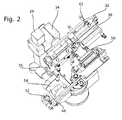
- the feed unit further has a base frame 24, which is formed according to the prior art. This base frame 24 has a pivot axis 26. It is a pivot arm 28 is provided which is pivotally connected about the pivot axis 26 to the base frame 24, it can between a pivoted position, as they FIG. 1 shows, and a rest position are pivoted. In the rest position, the swing arm 28 is out of the range of the spot welding electrodes 22.
- the feed unit further has an actuator 30 which is disposed between the base frame 24 and the pivot arm 28 and can perform the described pivoting movement between the two positions. It is associated with a control device 40, not shown.
- the feed unit further has a base part 32, which is arranged adjustable on the pivot arm 28.
- the pivot arm 28 has non-circular cross section, here a square cross section.
- the fastening means 34 are designed in a development, the base part 32 so that the base member 32 can be adjusted in different angular positions to the axis of the pivot arm 28.
- FIG. 3 shows a possible angular position.
- the feed unit further has a feed part 36, which is adjustable relative to the base part 32 between an active position and a passive position. Further adjustment options are not excluded.
- FIG. 3 shows the active position of the feed part 36 in dotted lines, the passive position is shown by solid lines.
- a drive 38 is provided, it is arranged between the base part 32 and the feed part 36 and is responsible for the movement of the feed part 36 between the two positions, which in FIG. 3 are shown to effect. This drive 38 is also connected to the control device 40.
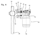
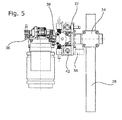
- a linear guide 42 is arranged between the base part 32 and the feed part 36. It uses two parallel waves connected to the base part 34. They are surrounded by sliding parts, which are connected to a plate. This plate forms the main part of the feed part 36. On this plate, the cap cutter 20 is attached. On this plate and the drive 38 is arranged.
- a linear guide and other guide means may be provided.
- a pivot axis may be provided on the base part 32, about which the feed part 36 can be pivoted. It is also a parallelogram with two parallelogram between base member 32 and feed part 36 possible.
- the linear guide 42 allows a displacement of the feed member 36 along a displacement path 44.
- This displacement path 44 is perpendicular to a rotation axis 46 of the cap cutter 22.
- the feed part 36 is in its passive position.
- the feed part 36 must first be brought into the active position, as in FIG. 3 shown with dash-dotted lines. Then a milling can be done.
- the cap cutter 22 is located outside the space between the two spot welding electrodes 22.
- a support arm 48 is pivotally mounted. It is pivotable about a pivot axis which runs parallel to the axis of rotation 46. He can choose between an active pivot position, the FIG. 3 in solid lines, wherein the position of the feed member 36 is also valid with solid lines, and are pivoted to a passive pivot position, it is dash-dotted lines in FIG. 3 shown for the same state of the feed part 36.
- the pivot angle is about 50 to 90, preferably about 70 °.
- a pivot drive 50 which is also connected to the control device 40. About a lifting device, the pivoting movement takes place. Also, the pivot drive 50 is mounted on the plate.
- a sensor 52 is arranged, in the embodiment shown is a pressure cell. Its disk axis is parallel to the axis of rotation 46. In the active pivot position shown in solid lines, the sensor 52 is located between the spot welding electrodes 22. When these are approached, the closing force can be determined. Other features can be detected using other sensors.
- the cap cutter 20 has a milling device 54 and a chip collecting device 56.
- the latter includes a hose 58 which connects a chip collecting container 60 with the milling device 54.
- This tube 58 can now be carried out either flexible, so that he out of FIG. 3 apparent movement of the milling device 54 participates at one end and at the other end, where it is connected to the chip collecting container 60, stationary, where it is fixed to the pivot arm 28. But it is also possible to build the tube 58 of two rigid sections, of which a portion with the milling device 54, as in FIG. 3 shown, and the other part is connected to the chip collection container 60. Only in the active position of the feed part both tube parts are in alignment with each other, they are brought by the sliding movement in this connection.
Landscapes
- Engineering & Computer Science (AREA)
- Mechanical Engineering (AREA)
- Resistance Welding (AREA)
- Milling Processes (AREA)
Applications Claiming Priority (2)
| Application Number | Priority Date | Filing Date | Title |
|---|---|---|---|
| DE102009029393 | 2009-09-11 | ||
| DE102009029433 | 2009-09-14 |
Publications (2)
| Publication Number | Publication Date |
|---|---|
| EP2295187A2 true EP2295187A2 (fr) | 2011-03-16 |
| EP2295187A3 EP2295187A3 (fr) | 2015-08-05 |
Family
ID=43413494
Family Applications (1)
| Application Number | Title | Priority Date | Filing Date |
|---|---|---|---|
| EP10176428.0A Withdrawn EP2295187A3 (fr) | 2009-09-11 | 2010-09-13 | Unité d'avance d'une fraise à capot destinée à fraiser la zone de soudure d'électrodes de soudure par point |
Country Status (1)
| Country | Link |
|---|---|
| EP (1) | EP2295187A3 (fr) |
Cited By (2)
| Publication number | Priority date | Publication date | Assignee | Title |
|---|---|---|---|---|
| CN103537847A (zh) * | 2013-10-22 | 2014-01-29 | 长城汽车股份有限公司 | 一种电极帽修磨装置及自动焊接系统 |
| DE202015103064U1 (de) | 2015-06-11 | 2015-06-30 | AEG SVS Schweißtechnik GmbH | Kappenfräser zum Befräsen von Punktschweißelektroden mit einer Fräseinheit und mit einer Vorschubeinheit |
Citations (5)
| Publication number | Priority date | Publication date | Assignee | Title |
|---|---|---|---|---|
| DE4213571C2 (de) | 1991-04-26 | 1996-08-14 | Honda Motor Co Ltd | Elektrodenspitzen-Abrichtgerät und Schneidwerkzeug für dieses |
| DE19825771A1 (de) | 1998-06-09 | 1999-12-16 | Bayerische Motoren Werke Ag | Vorrichtung zum Fräsen von Elektrodenkappen |
| EP0958092B1 (fr) | 1996-05-21 | 2003-07-02 | Peter-Stephan Lutz | Systeme de fraisage et procede pour fraiser la zone de soudage d'electrodes de soudage par points |
| US6666631B2 (en) | 2000-09-07 | 2003-12-23 | Fuji Jukogyo Kabushiki Kaisha | Electrode tip dressing apparatus |
| US6863597B2 (en) | 2001-06-27 | 2005-03-08 | Fuji Jukogyo Kabushiki Kaisha | Chip collecting apparatus for tip dresser |
Family Cites Families (4)
| Publication number | Priority date | Publication date | Assignee | Title |
|---|---|---|---|---|
| DE20106635U1 (de) * | 2001-04-17 | 2001-08-16 | Schweißtechnik Bräuer GmbH, 09488 Schönfeld | Kappenfräsanlage |
| JP2002361193A (ja) * | 2001-06-06 | 2002-12-17 | Kyokutoh Co Ltd | ドレッサー用吸引機 |
| US20030013395A1 (en) * | 2001-06-20 | 2003-01-16 | Fuji Jukogyo Kabushiki Kaisha | Chip collecting apparatus for tip dresser |
| ITMI20011867A1 (it) * | 2001-09-06 | 2003-03-06 | Advanced Technologies S R L | Dispositivo automatico per la riformatura di elettrodi in pinze di saldatura |
-
2010
- 2010-09-13 EP EP10176428.0A patent/EP2295187A3/fr not_active Withdrawn
Patent Citations (5)
| Publication number | Priority date | Publication date | Assignee | Title |
|---|---|---|---|---|
| DE4213571C2 (de) | 1991-04-26 | 1996-08-14 | Honda Motor Co Ltd | Elektrodenspitzen-Abrichtgerät und Schneidwerkzeug für dieses |
| EP0958092B1 (fr) | 1996-05-21 | 2003-07-02 | Peter-Stephan Lutz | Systeme de fraisage et procede pour fraiser la zone de soudage d'electrodes de soudage par points |
| DE19825771A1 (de) | 1998-06-09 | 1999-12-16 | Bayerische Motoren Werke Ag | Vorrichtung zum Fräsen von Elektrodenkappen |
| US6666631B2 (en) | 2000-09-07 | 2003-12-23 | Fuji Jukogyo Kabushiki Kaisha | Electrode tip dressing apparatus |
| US6863597B2 (en) | 2001-06-27 | 2005-03-08 | Fuji Jukogyo Kabushiki Kaisha | Chip collecting apparatus for tip dresser |
Cited By (2)
| Publication number | Priority date | Publication date | Assignee | Title |
|---|---|---|---|---|
| CN103537847A (zh) * | 2013-10-22 | 2014-01-29 | 长城汽车股份有限公司 | 一种电极帽修磨装置及自动焊接系统 |
| DE202015103064U1 (de) | 2015-06-11 | 2015-06-30 | AEG SVS Schweißtechnik GmbH | Kappenfräser zum Befräsen von Punktschweißelektroden mit einer Fräseinheit und mit einer Vorschubeinheit |
Also Published As
| Publication number | Publication date |
|---|---|
| EP2295187A3 (fr) | 2015-08-05 |
Similar Documents
| Publication | Publication Date | Title |
|---|---|---|
| DE202021106388U1 (de) | Vorrichtung für Anschweissmontage eines Stahlträgerhalters und Anlage zum Schweissen eines Stahlträgerhalters | |
| EP0734304B1 (fr) | Dispositif de soudage et/ou de decoupage | |
| EP3378823B1 (fr) | Grue | |
| EP2468449B1 (fr) | Dispositif et procédé destinés à la protection contre un rayon laser sur une machine de traitement par laser destinée à traiter des pièces avec des moyens pour estimer l'orientation de la surface d'appui de l'organe de protection | |
| DE3121637A1 (de) | "luenette zum halten von stangenfoermigen werkstuecken kreisfoermigen querschnitts" | |
| DE102018111496B4 (de) | Verfahren zum Rührreibschweißen | |
| DE102010041466B4 (de) | Vorrichtung zum Positionieren eines Werkstücks | |
| EP2223765B1 (fr) | Dispositif de pivotement d'un dispositif de rodage d'embouts d'électrodes de soudure par point | |
| WO2021179028A1 (fr) | Presse plieuse | |
| EP3010663B1 (fr) | Dispositif à butée arrière pour plieuse | |
| DE69909977T2 (de) | Vorrichtung zum Stumpf-Laserschweissen von Blechen (vorbestimmten Zuschnitten), die magnetische Rollen hat um die Bleche nach der Schweissposition zu bewegen und die aktive Klemmen hat, um die Bleche zu klemmen | |
| EP2846966B1 (fr) | Centre de transfert destiné à usiner au moins une pièce par enlèvement de matière, comprenant un système de compensation de position | |
| EP1136206A2 (fr) | Machine avec tête de fraisage pivotable | |
| WO2015135917A2 (fr) | Procédé pour faire fonctionner un robot et robot correspondant équipé d'un dispositif palpeur mécanique | |
| DE3831210A1 (de) | Schwenkeinrichtung fuer eine abschlagplatte zur positionierung von werkstuecken (materialanschlag) | |
| EP2295187A2 (fr) | Unité d'avance d'une fraise à capot destinée à fraiser la zone de soudure d'électrodes de soudure par point | |
| WO2007092974A1 (fr) | Électrode de soudage par points et pince de soudage par points avec une telle électrode | |
| DE102004031584B4 (de) | Schärfmaschine zum Scharfschleifen von Klingen | |
| EP3488967B1 (fr) | Dispositif d'usinage de pièces à usiner optiques, en particulier verres de lunettes | |
| EP1280622B1 (fr) | Dispositif de transfert et son procede de commande | |
| CH698147B1 (de) | Schleifmaschine und Verfahren zum Einrichten eines Werkstückträgers an einer Schleifmaschine. | |
| DE202015103064U1 (de) | Kappenfräser zum Befräsen von Punktschweißelektroden mit einer Fräseinheit und mit einer Vorschubeinheit | |
| DE3034700C2 (de) | Elektrische Widerstandsschweißzange | |
| DE20112510U1 (de) | Schweißeinrichtung | |
| EP4088852A1 (fr) | Procédé de détection des emplacements d'une ligne d'assemblage entre composants, ainsi que procédé de soudage ultérieur |
Legal Events
| Date | Code | Title | Description |
|---|---|---|---|
| PUAI | Public reference made under article 153(3) epc to a published international application that has entered the european phase |
Free format text: ORIGINAL CODE: 0009012 |
|
| AK | Designated contracting states |
Kind code of ref document: A2 Designated state(s): AL AT BE BG CH CY CZ DE DK EE ES FI FR GB GR HR HU IE IS IT LI LT LU LV MC MK MT NL NO PL PT RO SE SI SK SM TR |
|
| AX | Request for extension of the european patent |
Extension state: BA ME RS |
|
| PUAL | Search report despatched |
Free format text: ORIGINAL CODE: 0009013 |
|
| AK | Designated contracting states |
Kind code of ref document: A3 Designated state(s): AL AT BE BG CH CY CZ DE DK EE ES FI FR GB GR HR HU IE IS IT LI LT LU LV MC MK MT NL NO PL PT RO SE SI SK SM TR |
|
| AX | Request for extension of the european patent |
Extension state: BA ME RS |
|
| RIC1 | Information provided on ipc code assigned before grant |
Ipc: B23K 11/11 20060101ALI20150701BHEP Ipc: B23K 11/30 20060101AFI20150701BHEP |
|
| STAA | Information on the status of an ep patent application or granted ep patent |
Free format text: STATUS: THE APPLICATION IS DEEMED TO BE WITHDRAWN |
|
| 18D | Application deemed to be withdrawn |
Effective date: 20160206 |