EP2295523A2 - Hydrierung von Mitteldistillatkohlenwasserstoffen mit einem Gegenstromreaktor - Google Patents
Hydrierung von Mitteldistillatkohlenwasserstoffen mit einem Gegenstromreaktor Download PDFInfo
- Publication number
- EP2295523A2 EP2295523A2 EP10012480A EP10012480A EP2295523A2 EP 2295523 A2 EP2295523 A2 EP 2295523A2 EP 10012480 A EP10012480 A EP 10012480A EP 10012480 A EP10012480 A EP 10012480A EP 2295523 A2 EP2295523 A2 EP 2295523A2
- Authority
- EP
- European Patent Office
- Prior art keywords
- hydrogen
- effluent
- reaction zone
- stream
- hydrogenation
- Prior art date
- Legal status (The legal status is an assumption and is not a legal conclusion. Google has not performed a legal analysis and makes no representation as to the accuracy of the status listed.)
- Withdrawn
Links
Images




Classifications
-
- C—CHEMISTRY; METALLURGY
- C10—PETROLEUM, GAS OR COKE INDUSTRIES; TECHNICAL GASES CONTAINING CARBON MONOXIDE; FUELS; LUBRICANTS; PEAT
- C10G—CRACKING HYDROCARBON OILS; PRODUCTION OF LIQUID HYDROCARBON MIXTURES, e.g. BY DESTRUCTIVE HYDROGENATION, OLIGOMERISATION, POLYMERISATION; RECOVERY OF HYDROCARBON OILS FROM OIL-SHALE, OIL-SAND, OR GASES; REFINING MIXTURES MAINLY CONSISTING OF HYDROCARBONS; REFORMING OF NAPHTHA; MINERAL WAXES
- C10G65/00—Treatment of hydrocarbon oils by two or more hydrotreatment processes only
- C10G65/02—Treatment of hydrocarbon oils by two or more hydrotreatment processes only plural serial stages only
-
- C—CHEMISTRY; METALLURGY
- C10—PETROLEUM, GAS OR COKE INDUSTRIES; TECHNICAL GASES CONTAINING CARBON MONOXIDE; FUELS; LUBRICANTS; PEAT
- C10G—CRACKING HYDROCARBON OILS; PRODUCTION OF LIQUID HYDROCARBON MIXTURES, e.g. BY DESTRUCTIVE HYDROGENATION, OLIGOMERISATION, POLYMERISATION; RECOVERY OF HYDROCARBON OILS FROM OIL-SHALE, OIL-SAND, OR GASES; REFINING MIXTURES MAINLY CONSISTING OF HYDROCARBONS; REFORMING OF NAPHTHA; MINERAL WAXES
- C10G65/00—Treatment of hydrocarbon oils by two or more hydrotreatment processes only
- C10G65/02—Treatment of hydrocarbon oils by two or more hydrotreatment processes only plural serial stages only
- C10G65/04—Treatment of hydrocarbon oils by two or more hydrotreatment processes only plural serial stages only including only refining steps
-
- C—CHEMISTRY; METALLURGY
- C07—ORGANIC CHEMISTRY
- C07C—ACYCLIC OR CARBOCYCLIC COMPOUNDS
- C07C5/00—Preparation of hydrocarbons from hydrocarbons containing the same number of carbon atoms
-
- C—CHEMISTRY; METALLURGY
- C10—PETROLEUM, GAS OR COKE INDUSTRIES; TECHNICAL GASES CONTAINING CARBON MONOXIDE; FUELS; LUBRICANTS; PEAT
- C10G—CRACKING HYDROCARBON OILS; PRODUCTION OF LIQUID HYDROCARBON MIXTURES, e.g. BY DESTRUCTIVE HYDROGENATION, OLIGOMERISATION, POLYMERISATION; RECOVERY OF HYDROCARBON OILS FROM OIL-SHALE, OIL-SAND, OR GASES; REFINING MIXTURES MAINLY CONSISTING OF HYDROCARBONS; REFORMING OF NAPHTHA; MINERAL WAXES
- C10G65/00—Treatment of hydrocarbon oils by two or more hydrotreatment processes only
- C10G65/02—Treatment of hydrocarbon oils by two or more hydrotreatment processes only plural serial stages only
- C10G65/04—Treatment of hydrocarbon oils by two or more hydrotreatment processes only plural serial stages only including only refining steps
- C10G65/08—Treatment of hydrocarbon oils by two or more hydrotreatment processes only plural serial stages only including only refining steps at least one step being a hydrogenation of the aromatic hydrocarbons
-
- C—CHEMISTRY; METALLURGY
- C10—PETROLEUM, GAS OR COKE INDUSTRIES; TECHNICAL GASES CONTAINING CARBON MONOXIDE; FUELS; LUBRICANTS; PEAT
- C10G—CRACKING HYDROCARBON OILS; PRODUCTION OF LIQUID HYDROCARBON MIXTURES, e.g. BY DESTRUCTIVE HYDROGENATION, OLIGOMERISATION, POLYMERISATION; RECOVERY OF HYDROCARBON OILS FROM OIL-SHALE, OIL-SAND, OR GASES; REFINING MIXTURES MAINLY CONSISTING OF HYDROCARBONS; REFORMING OF NAPHTHA; MINERAL WAXES
- C10G2300/00—Aspects relating to hydrocarbon processing covered by groups C10G1/00 - C10G99/00
- C10G2300/10—Feedstock materials
- C10G2300/1037—Hydrocarbon fractions
- C10G2300/1048—Middle distillates
-
- C—CHEMISTRY; METALLURGY
- C10—PETROLEUM, GAS OR COKE INDUSTRIES; TECHNICAL GASES CONTAINING CARBON MONOXIDE; FUELS; LUBRICANTS; PEAT
- C10G—CRACKING HYDROCARBON OILS; PRODUCTION OF LIQUID HYDROCARBON MIXTURES, e.g. BY DESTRUCTIVE HYDROGENATION, OLIGOMERISATION, POLYMERISATION; RECOVERY OF HYDROCARBON OILS FROM OIL-SHALE, OIL-SAND, OR GASES; REFINING MIXTURES MAINLY CONSISTING OF HYDROCARBONS; REFORMING OF NAPHTHA; MINERAL WAXES
- C10G2300/00—Aspects relating to hydrocarbon processing covered by groups C10G1/00 - C10G99/00
- C10G2300/10—Feedstock materials
- C10G2300/1037—Hydrocarbon fractions
- C10G2300/1048—Middle distillates
- C10G2300/1055—Diesel having a boiling range of about 230 - 330 °C
-
- C—CHEMISTRY; METALLURGY
- C10—PETROLEUM, GAS OR COKE INDUSTRIES; TECHNICAL GASES CONTAINING CARBON MONOXIDE; FUELS; LUBRICANTS; PEAT
- C10G—CRACKING HYDROCARBON OILS; PRODUCTION OF LIQUID HYDROCARBON MIXTURES, e.g. BY DESTRUCTIVE HYDROGENATION, OLIGOMERISATION, POLYMERISATION; RECOVERY OF HYDROCARBON OILS FROM OIL-SHALE, OIL-SAND, OR GASES; REFINING MIXTURES MAINLY CONSISTING OF HYDROCARBONS; REFORMING OF NAPHTHA; MINERAL WAXES
- C10G2300/00—Aspects relating to hydrocarbon processing covered by groups C10G1/00 - C10G99/00
- C10G2300/20—Characteristics of the feedstock or the products
- C10G2300/201—Impurities
- C10G2300/202—Heteroatoms content, i.e. S, N, O, P
-
- C—CHEMISTRY; METALLURGY
- C10—PETROLEUM, GAS OR COKE INDUSTRIES; TECHNICAL GASES CONTAINING CARBON MONOXIDE; FUELS; LUBRICANTS; PEAT
- C10G—CRACKING HYDROCARBON OILS; PRODUCTION OF LIQUID HYDROCARBON MIXTURES, e.g. BY DESTRUCTIVE HYDROGENATION, OLIGOMERISATION, POLYMERISATION; RECOVERY OF HYDROCARBON OILS FROM OIL-SHALE, OIL-SAND, OR GASES; REFINING MIXTURES MAINLY CONSISTING OF HYDROCARBONS; REFORMING OF NAPHTHA; MINERAL WAXES
- C10G2300/00—Aspects relating to hydrocarbon processing covered by groups C10G1/00 - C10G99/00
- C10G2300/20—Characteristics of the feedstock or the products
- C10G2300/30—Physical properties of feedstocks or products
- C10G2300/301—Boiling range
-
- C—CHEMISTRY; METALLURGY
- C10—PETROLEUM, GAS OR COKE INDUSTRIES; TECHNICAL GASES CONTAINING CARBON MONOXIDE; FUELS; LUBRICANTS; PEAT
- C10G—CRACKING HYDROCARBON OILS; PRODUCTION OF LIQUID HYDROCARBON MIXTURES, e.g. BY DESTRUCTIVE HYDROGENATION, OLIGOMERISATION, POLYMERISATION; RECOVERY OF HYDROCARBON OILS FROM OIL-SHALE, OIL-SAND, OR GASES; REFINING MIXTURES MAINLY CONSISTING OF HYDROCARBONS; REFORMING OF NAPHTHA; MINERAL WAXES
- C10G2300/00—Aspects relating to hydrocarbon processing covered by groups C10G1/00 - C10G99/00
- C10G2300/40—Characteristics of the process deviating from typical ways of processing
- C10G2300/4018—Spatial velocity, e.g. LHSV, WHSV
-
- C—CHEMISTRY; METALLURGY
- C10—PETROLEUM, GAS OR COKE INDUSTRIES; TECHNICAL GASES CONTAINING CARBON MONOXIDE; FUELS; LUBRICANTS; PEAT
- C10G—CRACKING HYDROCARBON OILS; PRODUCTION OF LIQUID HYDROCARBON MIXTURES, e.g. BY DESTRUCTIVE HYDROGENATION, OLIGOMERISATION, POLYMERISATION; RECOVERY OF HYDROCARBON OILS FROM OIL-SHALE, OIL-SAND, OR GASES; REFINING MIXTURES MAINLY CONSISTING OF HYDROCARBONS; REFORMING OF NAPHTHA; MINERAL WAXES
- C10G2400/00—Products obtained by processes covered by groups C10G9/00 - C10G69/14
- C10G2400/04—Diesel oil
Definitions
- the present disclosure relates to a process for hydrogenation of a middle distillate feedstock such as diesel fuel to produce improved quality diesel product.
- the diesel fuel must meet certain specifications relative to sulfur, nitrogen, olefins and aromatics content, cetane index, boiling point (distillation) and gravity. More stringent regulations will require refiners to produce ultra low sulfur content diesel (ULSD) in the coming.years. Generally, this will force refiners to produce 10-50 wppm or lower sulfur.content diesel fuel.
- ULSD ultra low sulfur content diesel
- Desulfurization of hydrocarbon feedstocks by hydrotreating is known, i.e., by reacting the feedstock with hydrogen under appropriate conditions to remove the sulfur in the form of hydrogen sulfide (H 2 S)
- H 2 S hydrogen sulfide
- a process for the hydrogenation of a hydrocarbon feed.
- the process comprises contacting a major portion of the hydrocarbon feed with hydrogen in a counter-current manner in a first reaction zone under hydrogenation reaction conditions in the presence of a hydrogenation catalyst in at least a first catalyst bed wherein a liquid effluent exits at a bottom end of the first reaction zone and a hydrogen-containing gaseous effluent exits at a top end of the first reaction zone; and contacting a minor portion of the hydrocarbon feed with said hydrogen-containing gaseous effluent in a co-current manner in a second reaction zone having a catalyst bed positioned to receive said hydrogen-containing effluent of the first reaction zone.
- the process comprises (a) co-current contacting of the petroleum fraction with hydrogen in a first reaction zone in the presence of a first hydrogenation catalyst to produce a first effluent having a reduced heteroatom content; and, (b) contacting the first effluent with hydrogen in a counter-current manner in a second reaction zone in the presence of a second hydrogenation catalyst to produce a product having a heteroatom content of no more than about 50 ppm by weight.
- the process entails deep hydrogenation and achieves ultra low sulfur content diesel fuel for both new and existing facilities without major modifications typically associated with conventional processing schemes.
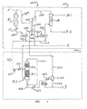
- FIG. 1 is a schematic diagram of the process of the invention using a co-current reactor in conjunction with a new counter-current reactor of the invention
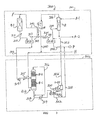
- FIGS. 2-4 are schematic diagrams of other process schemes of the invention employing both co-current and new counter-current reactors;
- FIG. 5 is a schematic diagram of a process scheme for the hydrogenation of a petroleum distillate using only a counter-current reactor
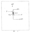
- FIG. 6 is a diagram of a subsequent dearomatization treatment which can be performed on the product of the hydrogenation process of the invention.
- FIG. 7 is a diagrammatic illustration of a multi-bed countercurrent reactor of the invention.
- the present invention can be used for hydrogenation of a petroleum fraction, particularly a middle distillate such as that to be used for diesel fuel. Hydrogenation can be employed for hydrotreatment, for example, to remove heteroatoms or for dearomatization (e.g., hydrodesulfurization, hydrodenitrogenation, hydrodearomatization).
- Hydrogenation can be employed for hydrotreatment, for example, to remove heteroatoms or for dearomatization (e.g., hydrodesulfurization, hydrodenitrogenation, hydrodearomatization).
- the processing scheme of the present invention employs a counter-current reactor which can be integrated into an existing hydrotreatment system.
- the counter-current reactor is implemented "outside the high pressure reaction loop" thus offering additional processing advantages, including lower installed cost, simpler revamp, no major piping / heat integration, no impact to the existing scrubber or the recycle gas compressor and reduced down time.
- the alternate scheme utilizes low cost base metal catalyst and offers improved product properties including aromatics reduction, cetane improvement and catalyst stability.
- the existing reactor operation is optimized so as to prepare feed to the new counter-current reactor.
- the counter-current reactor further treats the effluent from the existing reactor to achieve the required processing objectives.
- FIG. 1 a system 100 is shown for the hydrodesulfurization of a middle distillate.
- System 100 illustrates the revamping of a hydrotreating scheme outlined by 101 by the incorporation of counter-current reaction scheme 102.
- like numerical or letter designations indicate like processing equipment or streams.
- Feed F is a middle range petroleum fraction typically having the following properties as shown in Table 1:
- Co-current reactor includes a bed containing a suitable hydrodesulfurization catalyst such as nickel (Ni), cobalt (Co)., molybdenum (Mo), tungsten (W), and combinations thereof (such as Ni-Mo, Co-Mo, Ni-W, Co-Mo-Ni, Co-Mo-W), on a support such as silica, alumina, or silica-alumina.
- a suitable hydrodesulfurization catalyst such as nickel (Ni), cobalt (Co)., molybdenum (Mo), tungsten (W), and combinations thereof (such as Ni-Mo, Co-Mo, Ni-W, Co-Mo-Ni, Co-Mo-W)
- a support such as silica, alumina, or silica-alumina.
- Co-current hydrodesulfurization reaction conditions typically include a temperature of from about 200°C to about 450°C, a pressure of from about 300 psig to about 1,500 psig, and a space velocity of up to about 20 v/v/hr.
- the effluent 110 from reactor R-1 typically has a sulfur content of from about 100 ppm to about 1,000 ppm by weight.
- the at least partially desulfurized effluent (line 110) is cooled by heat exchanger 111 to a temperature of from about 200°C to about 380°C and sent to drum D-11 via line 110 where it is separated into a vapor and a liquid.
- the liquid is drawn off via line 112 and heated in heat exchanger 113 to a temperature of from about 225°C to about 370°C and then sent to countercurrent reactor R-2.
- the vapor from drum D-11 is further cooled by heat exchanger 115 and sent via line 114 to drum D-12 for further separation of vapor and liquid components.
- the vapor, containing hydrogen, hydrogen sulfide, and light hydrocarbon components, is added via line 120 to line 118 for transfer to drum D-13.
- the liquid is drawn off and sent via line 122 to stream 112 to be sent to reactor R-2.
- Counter-current reactor R-2 preferably includes two or more beds of catalyst, B-1 and B-2.
- Reactor R-2 includes two reaction zones: a first zone in which counter-current contacting of hydrocarbon and hydrogen takes place, and a second reaction zone wherein co-current contacting of hydrocarbon and hydrogen takes place. As shown in FIG. 1 , bed B-1 is in the first reaction zone and bed B-2 is in the second reaction zone.
- the hydrocarbon feed is introduced into reactor R-2 at a position between the first and second reaction zones. Each bed contains a hydrodesulfurization catalyst.
- Useful hydrodesulfurization catalysts include those such as mentioned above (e.g., Ni-Mo, Co-Mo, Ni-W on silica, alumina or silica-alumina support), as well as zeolites, noble metal catalysts, and the like.
- the liquid feed from line 112 is introduced into reactor R-2 between beds B-1 and B-2.
- Make-up hydrogen H is introduced at the bottom of the reactor R-2.
- Reactor R-2 operates at a temperature of from about 225°C to about 450°C, a pressure of from about 250 psig to about 1,500 psig, and a space velocity of from about 0.6 to about 5.0 LHSV.
- the hydrogen-containing gas exiting as an effluent from bed B-1 at the top of the first reaction zone entrains a minor portion of the hydrocarbon feed to the reactor. Any entrained hydrocarbon mist or vapor is reacted with the hydrogen-containing gas in the presence of the catalyst in bed B-2. Since both the hydrocarbon portion and the hydrogen-containing gas flow upward through bed B-1, the contacting is conducted in a co-current manner.
- a catalyst bed B-2 above the feed inlet so as to receive the effluent hydrogen-containing gas from the first reaction zone insures that no hydrocarbon passes through reactor R-2 without contacting hydrogen in the presence of a catalyst, thereby achieving the requirements of ultra low sulfur content.
- the overhead 116 from reactor R-2 is combined with the bottom liquid , and the total effluent of reactor R-2 is cooled in heat exchanger.117 and sent via line 118 to drum D-13.
- Liquid product P is separated and drawn off from drum D-13 via line 126, and the vapor is removed via line 124.
- the process and equipment described herein will provide a product P, useful as a diesel fuel component, having have a sulfur content of below 50 ppm by weight.
- the vapor overhead from drum D-13 (containing hydrogen, hydrogen sulfide and some hydrocarbon components) is drawn off via line 124 and sent through heat exchanger 125 for cooling and then through air cooling unit 130 and into drum D-14 for further separation of liquid and vapor.
- the liquid from drum D-14 is drawn off the bottom through line 134 and added to stream 126 to form the product stream P of ultra low sulfur content petroleum fraction.
- the vapor from drum D-14 (containing hydrogen, hydrogen sulfide and some light hydrocarbons such as methane ethane, etc.) is sent via line 132 to the bottom the absorber A wherein the upflow of vapor is contacted in a counter-current fashion with a downflowing absorbent to remove the hydrogen sulfide from the vapor stream.
- a lean amine absorbent A-1 is introduced at-the top of absorber 150.
- the amine absorbent is preferably, for example, an aqueous solution of an alkanolamine such as ethanolamine, diethanolamine, diisopropanolamine, methyldiethanolamine, triethanolamine, and the like.
- the overhead hydrogen rich vapor (including some light hydrocarbon components) from the absorber A is sent via line 136 to a compressor C-1 where it is compressed to a pressure of from about 400 psig to about 1,600 psig.
- the stream 128 exiting the compressor C-1 can be divided into stream 129 which is mixed with make-up hydrogen stream H for transfer to reactor R-2, and stream 127 which is sent through unit 125 for heat exchange with stream 124 to feed stream F.
- system 200 illustrates the revamping of a hydrotreating scheme outlined by 201 by the incorporation of counter-current reaction scheme 202.
- Feed F having a composition such as set fourth above, is combined with hydrogen (and light hydrocarbons) from stream 238, and then sent to reactor R-1 where at least partial hydrodesulfurization is effected under the reaction conditions set forth above.
- the effluent 210 from reactor R-1 is cooled in heat exchanger 211 and sent to drum D-21 where liquid and vapor are separated.
- Vapor stream 226 from drum D-21 is sent through heat exchanger 227 and air cooler 230 and then to drum D-24.
- the liquid bottom from drum D-21 is drawn off in stream 212 and added to stream 214 from drum D-24, which is then sent to reactor R-2 through an optional pump 215 and heat exchanger 216.
- Exchanger 216 controls the temperature of stream 214 to a temperature of from about 200°C to about 450°C
- the feed to reactor R-2 is introduced between catalyst beds B-1 and B-2.
- the liquid flows down through bed B-1 against an upflow of hydrogen.
- the make-up hydrogen from hydrogen source H is introduced below bed B-1 and flows upward. Upward flowing entrained hydrocarbon mist is further treated in bed B-2.
- the overhead vapor containing hydrogen, hydrogen sulfide and hydrocarbon vapor is combined with the bottom liquid from reactor R-2 to form stream 218.
- the total effluent 218 from reactor R-2 is cooled in heat exchanger 219 and sent to settling drum D-22.
- the liquid from drum D-22 is drawn off as a product stream P.
- the vapor from drum D-22 is further cooled in heat exchanger 223 and sent to drum D-23 for further separation.
- the bottoms from drum D-23 are sent via stream 222 to the product stream P of ultra low sulfur content petroleum fraction.
- the overhead vapor stream 224 is added to vapor stream 226 from drum D-21.
- stream 226 is cooled in heat exchanger 227, then cooled in air'cooler 230 and sent to drum D-24.
- the bottom liquid from drum D-24 is sent to reactor R-2 via line 214.
- the overhead vapor from drum D-24 containing hydrogen, hydrogen sulfide and light hydrocarbons is sent into absorber A where it is counter-current contacted with a stream of downflowing amine H 2 S absorbent such as described above.
- the overhead H 2 S-free vapor stream 232 containing mostly hydrogen with some light hydrocarbons is sent to compressor C-1 for compression to about 400 psig to about 1,600 psig.
- the compressor output stream 234 can be divided into stream 236, which is added to make-up hydrogen stream H, and stream 238, which is heat exchanged against stream 226 in exchanger 227 and then added to feed stream F for introduction into reactor R-1.
- system 300 illustrates the revamping of a hydrotreating scheme outlined by 301 by the incorporation of counter-current reaction scheme 302.
- Feed F having a composition as set forth above, is combined with stream 342 containing hydrogen and some light hydrocarbon components, and is introduced into reactor R-1 for at least partial hydrodesulfurization under the conditions stated above.
- the effluent 310 from reactor R-1 is cooled in heat exchanger 311 and sent to drum D-31 for separation of liquid and vapor.
- the liquid is sent via line 312 to reactor R-2 through an optional pump 314 and heat exchanger 315.
- Exchanger 315 controls the temperature of stream 312 to a temperature of from about 200°C to about 450°C.
- the feed to reactor R-2 is introduced between catalyst beds B-1 and B-2.
- the liquid flows down through bed B-1 against an upflow of hydrogen.
- the make-up hydrogen from hydrogen source H is introduced below bed B-1 and flows upward. Upward flowing entrained hydrocarbon mist is further treated in bed B-2.
- the overhead vapor containing hydrogen, hydrogen sulfide and hydrocarbon vapor is combined with the bottom liquid from reactor R-2.
- the total effluent 318 from reactor R-2 is cooled in heat exchanger 319 and sent to settling drum D-32.
- the liquid from drum. D-32 is drawn off via stream 322 to which is added the liquid bottoms from drum D-33 to form stream 328.
- Stream 328 is added to stream 344 from drum D-34 to form a product stream P.
- the vapor stream 320 from drum D-32 is further cooled in heat exchanger 321 and sent to drum D-33 for further separation.
- the bottoms from drum D-33 are sent via stream 324 to the stream 322, as mentioned above.
- the overhead vapor stream 326 from drum D-33 is added to the vapor stream 334 from drum D-34.
- the vapor stream 313 from drum D-31 is cooled by heat exchange in heat exchanger 325 and further cooled by air cooler 330 before being sent to drum D-34 for separation of vapor and liquid.
- the liquid bottom stream 344 from drum D-34 is combined with liquid stream 328 from drum D-32 to form a product stream P of ultra low sulfur content petroleum fraction.
- the overhead vapor stream from drum D-34 is combined with vapor stream 326 from drum D-33 and sent via line 334 to absorber A wherein it is counter-current contacted with a stream of downflowing amine H 2 S absorbent such as described above.
- the overhead H 2 S-free vapor stream 336 containing mostly hydrogen with some light hydrocarbons is sent to compressor C-1 for compression to about 400 psig to about 1,600 psig.
- the compressor output stream 338 can be divided into stream 340, which is added to make-up hydrogen stream H, and stream 342, which is heat exchanged against stream 313 in exchanger 325 and then added to feed stream F for introduction into reactor
- system 400 illustrates the revamping of a hydrotreating scheme outlined by 401 by the incorporation of counter-current reaction scheme 402.
- Feed F having a composition as set forth above, is combined with stream 434 containing hydrogen and some light hydrocarbon components, and is introduced into reactor R-1 for at least partial hydrodesulfurization under the conditions stated above.
- the effluent 410 from reactor R-1 is sent to drum D-41.
- the liquid bottom stream 414 from drum D-41 is cooled by heat exchanger 413.
- the vapor overhead 412 is combined with the liquid stream 414, which is then sent to reactor R-2.
- the feed to reactor R-2 is introduced between catalyst beds B-1 and B-2. The liquid flows down through bed B-1 against an upflow of hydrogen.
- the make-up hydrogen from hydrogen source H is introduced below bed B-1 and flows upward. Upward flowing entrained hydrocarbon mist is further treated in bed B-2.
- the bottom effluent stream 418 from reactor R-2 is sent via line 418 through cooler 417 into drum D-42.
- the overhead vapor 416 from reactor R-2 is added to stream 418 prior to cooling in cooler 417.
- the liquid bottoms from drum D-42 is sent via stream 422 to become a product stream P.
- the overhead 420 from the drum D-42 is cooled by heat exchange in heat exchanger 425 and further cooled by air cooler 430 before being sent to drum D-43 for separation of vapor and liquid.
- the liquid bottom stream 424 from drum D-43 is combined with liquid stream 422 from drum D-42 to form a product stream P of ultra low sulfur content petroleum fraction.
- the overhead vapor stream from drum D-43 is sent via line 426 to absorber A wherein it is counter-current contacted with a stream of downflowing amine H 2 S absorbent such as described above.
- the overhead H 2 S-free vapor stream 428 containing mostly hydrogen with some light hydrocarbons is sent to compressor C-1 for compression to about 400 psig to about 1,600 psig.
- the compressor output stream is divided into stream 432, which is added to make-up hydrogen stream H, and stream 434, which is heat exchanged against stream 420 in exchanger 425 and then added to feed stream F for introduction into reactor R-1.
- system 500 is shown wherein a co-current reactor R-1 is not employed to pretreat the feed by partial hydrotreating. Rather, only reactor R-2 is used for hydrogenation.
- Feed F is heated in heat exchanger 510 and then in heat exchanger 512, and then sent for further heating in heater 514 to a temperature of from about 200°C to about 450°C.
- the heated feed is then introduced into reactor R-2 in between beds B-1 and B-2, as explained above.
- Hydrogen stream 529 is introduced at the bottom of reactor R-2 and flows upward against the downflow of liquid petroleum distillate.
- entrained hydrocarbons carried by the upflow of gas enter bed B-2 and are subjected to hydrotreating so that no portion of the feed F exits the reactor R-2 without hydrotreatment.
- the overhead stream 516 from reactor R-2 is cooled in heat exchanger 510 by exchanging heat to the incoming feed F, and is then sent to drum D-51 for separation of liquid and vapor.
- the liquid bottoms from drum D-51 are sent via stream 520 to join stream 534, the liquid bottoms from drum D-53, so as to provide a product stream P.
- the overhead stream 532 from drum D-53 is combined with the outflow of compressor C-2 to form stream 523, which is cooled in heat exchanger 524 and then sent to drum D-52 for further separation of liquid and vapor.
- the .,liquid bottoms from drum D-52 is sent via stream 528 to the bottom stream 534 from drum D-53 so as to provide the ultra low sulfur content product P.
- the overhead 529 from drum D-52 is sent to compressor C-3 for compression, and is then sent to the bottom of reactor R-2.
- the overall compression between C-2 and C-3 is about 300 psig to about 1,600 psig.
- system 600 includes a reactor 610 for hydrodearomatization containing a bed B-3 of hydrogenation catalyst.
- the reactor is typically operated at a temperature of from about 200°C to about 400°C, a pressure of from about 400 psig to about 1,600 psig and a space velocity of from about 0.3 to about 6 LHSV, preferably about 3.5 LHSV.
- Various hydrogenation processes are known and disclosed, for example, in U.S. Patent No. 5,183,556 , which is herein incorporated by reference.
- the catalyst in bed B-3 can be a noble metal or non-noble metal catalyst supported silica, alumina, silica-alumina, zirconia, or other metal oxide.
- Hydrogen from hydrogen source H is introduced into the bottom of reactor 610 and flows upward against the downflow of petroleum distillate fraction.
- the overhead vapor is removed via stream 602, and the bottom effluent containing dearomatized petroleum distillate is removed via stream 603.
- Reactor R-3 contains three spaced-apart catalyst beds, B-1a, B-1b and B-2.
- the feed F is introduced between the middle bed B-1b and the uppermost bed B-2.
- Hydrogen is introduced via lines H-1 and H-2.
- the H-1 input to the reactor R-3 is positioned beneath the lowest bed B-1a, and the H-2 input to the reactor R-3 is positioned above bed B-1a and below bed B-1b.
- Hydrogen flows upward against the downflow of petroleum distillate feed F, and hydrogenation of feed F (e.g., hydrodesulfurization, hydrodenitrogenation) is effected in beds B-1a and B-1b by counter-current contacting with hydrogen.
- hydrocarbon components can be entrained in the upward flow of hydrogen, and these components are hydrogenated in bed B-2 so that all of the feed is subjected to hydrogenation.
- the overhead vapor stream V contains excess hydrogen, hydrogen sulfide and some light hydrocarbon components.
- the liquid effluent E taken from the bottom of the reactor contains ultra low sulfur content petroleum distillate (e.g., diesel fuel).
- a feedstock was provided having the following range of properties:
- the feedstock was treated in a hydrogenation system having a counter-current reactor in accordance with the invention.
- the reaction conditions included a temperature of 346°C, a pressure of 750 psig, a space velocity of 1.6 LHSV, and a hydrogenation catalyst comprising NiMo on a silica support.
- the resulting product had an API Gravity of 38.6, a sulfur content of 8 ppm by weight, and a nitrogen content of less than 1 ppm by weight.
- first and second reaction zones can be situated in different reactor shells as well as a single reactor shell.
Landscapes
- Chemical & Material Sciences (AREA)
- Oil, Petroleum & Natural Gas (AREA)
- Organic Chemistry (AREA)
- Engineering & Computer Science (AREA)
- Chemical Kinetics & Catalysis (AREA)
- General Chemical & Material Sciences (AREA)
- Production Of Liquid Hydrocarbon Mixture For Refining Petroleum (AREA)
- Organic Low-Molecular-Weight Compounds And Preparation Thereof (AREA)
Applications Claiming Priority (2)
| Application Number | Priority Date | Filing Date | Title |
|---|---|---|---|
| US10/449,046 US7247235B2 (en) | 2003-05-30 | 2003-05-30 | Hydrogenation of middle distillate using a counter-current reactor |
| EP04753693A EP1644464A2 (de) | 2003-05-30 | 2004-05-28 | Hydrierung eines mitteldestillats unter einsatz eines gegenstromreaktors |
Related Parent Applications (1)
| Application Number | Title | Priority Date | Filing Date |
|---|---|---|---|
| EP04753693.3 Division | 2004-05-28 |
Publications (2)
| Publication Number | Publication Date |
|---|---|
| EP2295523A2 true EP2295523A2 (de) | 2011-03-16 |
| EP2295523A3 EP2295523A3 (de) | 2012-05-02 |
Family
ID=33451678
Family Applications (4)
| Application Number | Title | Priority Date | Filing Date |
|---|---|---|---|
| EP10012484A Withdrawn EP2295524A3 (de) | 2003-05-30 | 2004-05-28 | Hydrierung von Mitteldistillatkohlenwasserstoffen mit einem Gegenstromreaktor |
| EP10012485A Withdrawn EP2295525A3 (de) | 2003-05-30 | 2004-05-28 | Hydrierung von Mitteldistillatkohlenwasserstoffen mit einem Gegenstromreaktor |
| EP04753693A Withdrawn EP1644464A2 (de) | 2003-05-30 | 2004-05-28 | Hydrierung eines mitteldestillats unter einsatz eines gegenstromreaktors |
| EP10012480A Withdrawn EP2295523A3 (de) | 2003-05-30 | 2004-05-28 | Hydrierung von Mitteldistillatkohlenwasserstoffen mit einem Gegenstromreaktor |
Family Applications Before (3)
| Application Number | Title | Priority Date | Filing Date |
|---|---|---|---|
| EP10012484A Withdrawn EP2295524A3 (de) | 2003-05-30 | 2004-05-28 | Hydrierung von Mitteldistillatkohlenwasserstoffen mit einem Gegenstromreaktor |
| EP10012485A Withdrawn EP2295525A3 (de) | 2003-05-30 | 2004-05-28 | Hydrierung von Mitteldistillatkohlenwasserstoffen mit einem Gegenstromreaktor |
| EP04753693A Withdrawn EP1644464A2 (de) | 2003-05-30 | 2004-05-28 | Hydrierung eines mitteldestillats unter einsatz eines gegenstromreaktors |
Country Status (11)
| Country | Link |
|---|---|
| US (1) | US7247235B2 (de) |
| EP (4) | EP2295524A3 (de) |
| JP (2) | JP5124141B2 (de) |
| CN (2) | CN100540635C (de) |
| BR (1) | BRPI0410819B1 (de) |
| CA (1) | CA2526659C (de) |
| MX (1) | MXPA05012731A (de) |
| RU (1) | RU2304609C2 (de) |
| UA (1) | UA88261C2 (de) |
| WO (1) | WO2004108637A2 (de) |
| ZA (1) | ZA200509685B (de) |
Families Citing this family (21)
| Publication number | Priority date | Publication date | Assignee | Title |
|---|---|---|---|---|
| US7247235B2 (en) * | 2003-05-30 | 2007-07-24 | Abb Lummus Global Inc, | Hydrogenation of middle distillate using a counter-current reactor |
| US7507328B2 (en) * | 2004-12-27 | 2009-03-24 | Exxonmobile Research And Engineering Company | Selective hydrodesulfurization and mercaptan decomposition process with interstage separation |
| US20070289900A1 (en) * | 2006-06-14 | 2007-12-20 | Alvarez Walter E | Hydrogenation of polynuclear aromatic compounds |
| US20080159928A1 (en) * | 2006-12-29 | 2008-07-03 | Peter Kokayeff | Hydrocarbon Conversion Process |
| FR2923490B1 (fr) * | 2007-11-12 | 2009-12-18 | Inst Francais Du Petrole | Procede d'hydroconversion de charges lourdes en lit bouillonnant avec injection de la charge en tete de reacteur |
| CN101434381B (zh) * | 2008-10-24 | 2011-07-13 | 上海华畅环保设备发展有限公司 | 短流程循环氢脱硫方法与装置 |
| US8020838B2 (en) * | 2009-03-31 | 2011-09-20 | Uop Llc | Contacting stages for co-current contacting apparatuses |
| US8424181B2 (en) * | 2009-04-17 | 2013-04-23 | Exxonmobil Research And Engineering Company | High pressure revamp of low pressure distillate hydrotreating process units |
| WO2011061576A1 (en) * | 2009-11-20 | 2011-05-26 | Total Raffinage Marketing | Process for the production of hydrocarbon fluids having a low aromatic content |
| CN102311759B (zh) * | 2010-07-07 | 2015-02-18 | 中国石油化工股份有限公司 | 一种柴油加氢脱硫方法 |
| EP2691495A4 (de) * | 2011-03-31 | 2014-11-12 | Uop Llc | Verfahren und vorrichtung zur wasserstoffbehandlung zweier fluidströme |
| CN104011181B (zh) | 2011-11-04 | 2017-02-15 | 沙特阿拉伯石油公司 | 具有集成中间氢分离和纯化的加氢处理和芳烃饱和方法 |
| CN103773474B (zh) * | 2012-10-24 | 2016-03-30 | 中国石油化工股份有限公司 | 一种气相、液相混合加氢工艺方法 |
| FR3013722B1 (fr) * | 2013-11-28 | 2015-12-04 | Ifp Energies Now | Procede d'hydrotraitement d'un gazole dans des reacteurs en serie avec recyclage d'hydrogene. |
| US10273420B2 (en) | 2014-10-27 | 2019-04-30 | Uop Llc | Process for hydrotreating a hydrocarbons stream |
| CN106701173B (zh) * | 2015-11-18 | 2018-08-10 | 中国石油天然气股份有限公司 | 液相加氢装置及方法 |
| CN106701180B (zh) * | 2015-11-18 | 2018-09-04 | 中国石油天然气股份有限公司 | 液相加氢装置及方法 |
| JP7147760B2 (ja) * | 2017-07-04 | 2022-10-05 | 三菱ケミカル株式会社 | 芳香族炭化水素の製造方法 |
| PL3802745T3 (pl) | 2018-05-25 | 2024-10-14 | Shell Internationale Research Maatschappij B.V. | Proces hydrokrakingu do wytwarzania średniego destylatu z lekkiego surowca węglowodorowego |
| CN112142551B (zh) * | 2020-09-08 | 2023-06-16 | 德州中科易工工程技术有限公司 | 一种铜基催化剂催化乙炔氢氯化合成氯乙烯的装置及方法 |
| US20260035320A1 (en) * | 2024-07-31 | 2026-02-05 | Uop Llc | Process for hydrogenating a hydrocarbon stream with heat recovery |
Citations (1)
| Publication number | Priority date | Publication date | Assignee | Title |
|---|---|---|---|---|
| US5183556A (en) | 1991-03-13 | 1993-02-02 | Abb Lummus Crest Inc. | Production of diesel fuel by hydrogenation of a diesel feed |
Family Cites Families (29)
| Publication number | Priority date | Publication date | Assignee | Title |
|---|---|---|---|---|
| US3767562A (en) * | 1971-09-02 | 1973-10-23 | Lummus Co | Production of jet fuel |
| US3775291A (en) * | 1971-09-02 | 1973-11-27 | Lummus Co | Production of jet fuel |
| US3846278A (en) * | 1971-09-02 | 1974-11-05 | Lummus Co | Production of jet fuel |
| US3761399A (en) * | 1971-12-08 | 1973-09-25 | Gulf Research Development Co | Two zone hydrodesulfurization of asphaltic fuel oil |
| US3897329A (en) * | 1973-12-26 | 1975-07-29 | Texaco Inc | Spit flow hydrodesulfurization of petroleum fraction |
| US4021330A (en) * | 1975-09-08 | 1977-05-03 | Continental Oil Company | Hydrotreating a high sulfur, aromatic liquid hydrocarbon |
| JPS57123290A (en) * | 1981-01-25 | 1982-07-31 | Chiyoda Chem Eng & Constr Co Ltd | Method for converting heavy hydrocarbon oil into light fractions |
| US4576709A (en) * | 1982-09-02 | 1986-03-18 | Ashland Oil, Inc. | Catalytic upgrading of reduced crudes and residual oils with a coke selective catalyst |
| US5522983A (en) * | 1992-02-06 | 1996-06-04 | Chevron Research And Technology Company | Hydrocarbon hydroconversion process |
| US5643442A (en) * | 1994-07-19 | 1997-07-01 | Exxon Research And Engineering Company | Membrane process for enhanced distillate or hydrotreated distillate aromatics reduction |
| US5730860A (en) * | 1995-08-14 | 1998-03-24 | The Pritchard Corporation | Process for desulfurizing gasoline and hydrocarbon feedstocks |
| US20010001450A1 (en) | 1996-08-23 | 2001-05-24 | Gerald E. Markley | Multi-stage countercurrent hydrotreating process |
| US5942197A (en) * | 1996-08-23 | 1999-08-24 | Exxon Research And Engineering Co | Countercurrent reactor |
| US6153086A (en) * | 1996-08-23 | 2000-11-28 | Exxon Research And Engineering Company | Combination cocurrent and countercurrent staged hydroprocessing with a vapor stage |
| US6495029B1 (en) | 1997-08-22 | 2002-12-17 | Exxon Research And Engineering Company | Countercurrent desulfurization process for refractory organosulfur heterocycles |
| US6623621B1 (en) | 1998-12-07 | 2003-09-23 | Exxonmobil Research And Engineering Company | Control of flooding in a countercurrent flow reactor by use of temperature of liquid product stream |
| EP1151060A4 (de) | 1998-12-08 | 2010-08-18 | Exxonmobil Res & Eng Co | Erzeugung von destillaten mit geringem schwefel- und aromatengehalt |
| US6241876B1 (en) * | 1998-12-30 | 2001-06-05 | Mobil Oil Corporation | Selective ring opening process for producing diesel fuel with increased cetane number |
| FR2795420B1 (fr) | 1999-06-25 | 2001-08-03 | Inst Francais Du Petrole | Procede d'hydrotraitement d'un distillat moyen dans deux zones successives comprenant une zone intermediaire de stripage de l'effluent de la premiere zone avec condensation des produits lourds sortant en tete du strippeur |
| US6312586B1 (en) * | 1999-09-27 | 2001-11-06 | Uop Llc | Multireactor parallel flow hydrocracking process |
| US6589416B2 (en) | 2000-07-21 | 2003-07-08 | Exxonmobil Research And Engineering Company | Method and catalyst for opening naphthenic rings of naphthenic ring-containing compounds |
| US6402940B1 (en) | 2000-09-01 | 2002-06-11 | Unipure Corporation | Process for removing low amounts of organic sulfur from hydrocarbon fuels |
| US6623622B2 (en) | 2000-10-10 | 2003-09-23 | Exxonmobil Research And Engineering Company | Two stage diesel fuel hydrotreating and stripping in a single reaction vessel |
| US6444116B1 (en) | 2000-10-10 | 2002-09-03 | Intevep, S.A. | Process scheme for sequentially hydrotreating-hydrocracking diesel and vacuum gas oil |
| CN1133721C (zh) * | 2001-01-05 | 2004-01-07 | 中国石油化工集团公司 | 一种烃类加氢处理工艺 |
| US6444118B1 (en) * | 2001-02-16 | 2002-09-03 | Catalytic Distillation Technologies | Process for sulfur reduction in naphtha streams |
| US7344633B2 (en) * | 2001-04-19 | 2008-03-18 | Shell Oil Company | Process to prepare a base oil having a high saturates content |
| CN1309808C (zh) * | 2001-11-16 | 2007-04-11 | 国际壳牌研究有限公司 | 逆流加氢处理的方法 |
| US7247235B2 (en) * | 2003-05-30 | 2007-07-24 | Abb Lummus Global Inc, | Hydrogenation of middle distillate using a counter-current reactor |
-
2003
- 2003-05-30 US US10/449,046 patent/US7247235B2/en not_active Expired - Lifetime
-
2004
- 2004-05-28 EP EP10012484A patent/EP2295524A3/de not_active Withdrawn
- 2004-05-28 RU RU2005141451/04A patent/RU2304609C2/ru active
- 2004-05-28 EP EP10012485A patent/EP2295525A3/de not_active Withdrawn
- 2004-05-28 CA CA2526659A patent/CA2526659C/en not_active Expired - Fee Related
- 2004-05-28 EP EP04753693A patent/EP1644464A2/de not_active Withdrawn
- 2004-05-28 UA UAA200511337A patent/UA88261C2/ru unknown
- 2004-05-28 JP JP2006533493A patent/JP5124141B2/ja not_active Expired - Fee Related
- 2004-05-28 BR BRPI0410819-1A patent/BRPI0410819B1/pt not_active IP Right Cessation
- 2004-05-28 EP EP10012480A patent/EP2295523A3/de not_active Withdrawn
- 2004-05-28 WO PCT/US2004/016910 patent/WO2004108637A2/en not_active Ceased
- 2004-05-28 CN CNB2004800150342A patent/CN100540635C/zh not_active Expired - Fee Related
- 2004-05-28 MX MXPA05012731A patent/MXPA05012731A/es active IP Right Grant
- 2004-05-28 CN CN200810095418.XA patent/CN101412927B/zh not_active Expired - Fee Related
-
2005
- 2005-11-30 ZA ZA200509685A patent/ZA200509685B/en unknown
-
2012
- 2012-07-26 JP JP2012165921A patent/JP5572185B2/ja not_active Expired - Fee Related
Patent Citations (1)
| Publication number | Priority date | Publication date | Assignee | Title |
|---|---|---|---|---|
| US5183556A (en) | 1991-03-13 | 1993-02-02 | Abb Lummus Crest Inc. | Production of diesel fuel by hydrogenation of a diesel feed |
Also Published As
| Publication number | Publication date |
|---|---|
| ZA200509685B (en) | 2006-10-25 |
| CN1798824A (zh) | 2006-07-05 |
| CA2526659A1 (en) | 2004-12-16 |
| JP5572185B2 (ja) | 2014-08-13 |
| RU2304609C2 (ru) | 2007-08-20 |
| WO2004108637A2 (en) | 2004-12-16 |
| EP2295525A2 (de) | 2011-03-16 |
| EP1644464A2 (de) | 2006-04-12 |
| JP2012246492A (ja) | 2012-12-13 |
| US20040238409A1 (en) | 2004-12-02 |
| EP2295525A3 (de) | 2012-05-02 |
| EP2295524A3 (de) | 2012-05-02 |
| US7247235B2 (en) | 2007-07-24 |
| CN100540635C (zh) | 2009-09-16 |
| JP5124141B2 (ja) | 2013-01-23 |
| WO2004108637A3 (en) | 2005-04-14 |
| BRPI0410819A (pt) | 2006-06-27 |
| KR20060054183A (ko) | 2006-05-22 |
| BRPI0410819B1 (pt) | 2015-04-14 |
| CA2526659C (en) | 2013-07-16 |
| CN101412927A (zh) | 2009-04-22 |
| CN101412927B (zh) | 2015-05-20 |
| MXPA05012731A (es) | 2006-02-22 |
| RU2005141451A (ru) | 2006-06-10 |
| JP2007502906A (ja) | 2007-02-15 |
| UA88261C2 (ru) | 2009-10-12 |
| EP2295523A3 (de) | 2012-05-02 |
| EP2295524A2 (de) | 2011-03-16 |
Similar Documents
| Publication | Publication Date | Title |
|---|---|---|
| JP5572185B2 (ja) | 向流反応器を用いる中間留出物の水素化 | |
| JP4434750B2 (ja) | 重質軽油から高品質留出油を生産するための新しい水素化分解法 | |
| KR100930985B1 (ko) | 중간 증류물 비등범위에서 외부 공급원료와 혼합되어마일드 수소첨가분해장치 및 감압경유 수소처리장치로부터고품질의 중간 증류물을 제조하는 방법 | |
| US6824673B1 (en) | Production of low sulfur/low aromatics distillates | |
| KR20030051375A (ko) | 방향성 화합물의 포화가 개선된 디젤을 최대화하는수소첨가분해 방법 | |
| EP1831333B1 (de) | Zweistufige hydrodesulfurierung von cracknaphthaströmen mit leichtnaphtha-bypass oder entfernung | |
| EP1151060A1 (de) | Erzeugung von destillaten mit geringem schwefel- und aromatengehalt | |
| CN101113126A (zh) | 含烯烃的轻烃催化加氢的方法 | |
| US9574141B2 (en) | Wet start-up method for hydrogenation unit, energy-saving hydrogenation process and hydrogenation apparatus | |
| CN111321005B (zh) | 一种低能耗、长周期生产柴油的加氢工艺 | |
| JP2004511623A (ja) | 単一反応槽におけるディーゼル燃料油の二段水素化およびストリッピング | |
| US7431828B2 (en) | Process for desulphurization of a hydrocarbon stream with a reduced consumption of hydrogen | |
| JP2005521778A (ja) | 結合された水素化処理 | |
| KR101070519B1 (ko) | 역류 반응장치를 이용하는 중간유분의 수소첨가 방법 | |
| CA2402126C (en) | Production of low sulfur/low aromatics distillates | |
| CN1362480A (zh) | 一种烃类加氢处理工艺 | |
| JP2009040844A (ja) | 改質原油の製造方法 | |
| CN113462431A (zh) | 一种生产柴油和喷气燃料的方法 | |
| AU2001251658A1 (en) | Production of low sulfur/low aromatics distillates | |
| CA2352887C (en) | Production of low sulfur/low aromatics distillates | |
| CN100523143C (zh) | 一种汽油脱硫降烯烃的方法 |
Legal Events
| Date | Code | Title | Description |
|---|---|---|---|
| PUAI | Public reference made under article 153(3) epc to a published international application that has entered the european phase |
Free format text: ORIGINAL CODE: 0009012 |
|
| 17P | Request for examination filed |
Effective date: 20101001 |
|
| AC | Divisional application: reference to earlier application |
Ref document number: 1644464 Country of ref document: EP Kind code of ref document: P |
|
| AK | Designated contracting states |
Kind code of ref document: A2 Designated state(s): AT BE BG CH CY CZ DE DK EE ES FI FR GB GR HU IE IT LI LU MC NL PL PT RO SE SI SK TR |
|
| RIN1 | Information on inventor provided before grant (corrected) |
Inventor name: VIRDI, HARJEET Inventor name: ROY, ARUP Inventor name: NGUYEN, THU-HUONG |
|
| PUAL | Search report despatched |
Free format text: ORIGINAL CODE: 0009013 |
|
| AK | Designated contracting states |
Kind code of ref document: A3 Designated state(s): AT BE BG CH CY CZ DE DK EE ES FI FR GB GR HU IE IT LI LU MC NL PL PT RO SE SI SK TR |
|
| RIC1 | Information provided on ipc code assigned before grant |
Ipc: C10G 65/04 20060101AFI20120326BHEP |
|
| 17Q | First examination report despatched |
Effective date: 20121217 |
|
| STAA | Information on the status of an ep patent application or granted ep patent |
Free format text: STATUS: THE APPLICATION IS DEEMED TO BE WITHDRAWN |
|
| 18D | Application deemed to be withdrawn |
Effective date: 20130430 |