EP2295710A2 - Barrière contre la pression de trou de forage actionnée à distance et son procédé d'utilisation - Google Patents
Barrière contre la pression de trou de forage actionnée à distance et son procédé d'utilisation Download PDFInfo
- Publication number
- EP2295710A2 EP2295710A2 EP10173537A EP10173537A EP2295710A2 EP 2295710 A2 EP2295710 A2 EP 2295710A2 EP 10173537 A EP10173537 A EP 10173537A EP 10173537 A EP10173537 A EP 10173537A EP 2295710 A2 EP2295710 A2 EP 2295710A2
- Authority
- EP
- European Patent Office
- Prior art keywords
- downhole pressure
- agent
- pressure barrier
- plug member
- activating
- Prior art date
- Legal status (The legal status is an assumption and is not a legal conclusion. Google has not performed a legal analysis and makes no representation as to the accuracy of the status listed.)
- Withdrawn
Links
- 230000004888 barrier function Effects 0.000 title claims abstract description 86
- 238000000034 method Methods 0.000 title claims description 12
- 230000003213 activating effect Effects 0.000 claims abstract description 53
- 238000004891 communication Methods 0.000 claims abstract description 36
- 238000002485 combustion reaction Methods 0.000 claims abstract description 21
- 239000003795 chemical substances by application Substances 0.000 claims description 106
- 239000012530 fluid Substances 0.000 claims description 73
- 229910052751 metal Inorganic materials 0.000 claims description 21
- 239000002184 metal Substances 0.000 claims description 21
- 239000000203 mixture Substances 0.000 claims description 20
- 239000004576 sand Substances 0.000 claims description 15
- 150000003839 salts Chemical class 0.000 claims description 14
- 229910044991 metal oxide Inorganic materials 0.000 claims description 10
- 150000004706 metal oxides Chemical class 0.000 claims description 10
- 239000000843 powder Substances 0.000 claims description 10
- 230000004913 activation Effects 0.000 claims description 9
- XLYOFNOQVPJJNP-UHFFFAOYSA-N water Substances O XLYOFNOQVPJJNP-UHFFFAOYSA-N 0.000 claims description 5
- 230000000712 assembly Effects 0.000 description 23
- 238000000429 assembly Methods 0.000 description 23
- VYPSYNLAJGMNEJ-UHFFFAOYSA-N Silicium dioxide Chemical compound O=[Si]=O VYPSYNLAJGMNEJ-UHFFFAOYSA-N 0.000 description 16
- 238000001994 activation Methods 0.000 description 12
- 238000006243 chemical reaction Methods 0.000 description 10
- FYYHWMGAXLPEAU-UHFFFAOYSA-N Magnesium Chemical compound [Mg] FYYHWMGAXLPEAU-UHFFFAOYSA-N 0.000 description 6
- 229910052749 magnesium Inorganic materials 0.000 description 6
- 239000011777 magnesium Substances 0.000 description 6
- 238000007789 sealing Methods 0.000 description 6
- 239000004020 conductor Substances 0.000 description 5
- 239000000470 constituent Substances 0.000 description 5
- 238000009434 installation Methods 0.000 description 4
- 239000003921 oil Substances 0.000 description 4
- 229910001220 stainless steel Inorganic materials 0.000 description 4
- 239000010935 stainless steel Substances 0.000 description 4
- QPLDLSVMHZLSFG-UHFFFAOYSA-N Copper oxide Chemical compound [Cu]=O QPLDLSVMHZLSFG-UHFFFAOYSA-N 0.000 description 3
- 230000015572 biosynthetic process Effects 0.000 description 3
- 238000011109 contamination Methods 0.000 description 3
- 239000007789 gas Substances 0.000 description 3
- JEIPFZHSYJVQDO-UHFFFAOYSA-N iron(III) oxide Inorganic materials O=[Fe]O[Fe]=O JEIPFZHSYJVQDO-UHFFFAOYSA-N 0.000 description 3
- 238000004519 manufacturing process Methods 0.000 description 3
- 239000011159 matrix material Substances 0.000 description 3
- 229910001120 nichrome Inorganic materials 0.000 description 3
- 230000002093 peripheral effect Effects 0.000 description 3
- 229920001187 thermosetting polymer Polymers 0.000 description 3
- 239000004634 thermosetting polymer Substances 0.000 description 3
- 239000004593 Epoxy Substances 0.000 description 2
- 229910052782 aluminium Inorganic materials 0.000 description 2
- XAGFODPZIPBFFR-UHFFFAOYSA-N aluminium Chemical compound [Al] XAGFODPZIPBFFR-UHFFFAOYSA-N 0.000 description 2
- 238000005056 compaction Methods 0.000 description 2
- QDOXWKRWXJOMAK-UHFFFAOYSA-N dichromium trioxide Chemical compound O=[Cr]O[Cr]=O QDOXWKRWXJOMAK-UHFFFAOYSA-N 0.000 description 2
- 239000013536 elastomeric material Substances 0.000 description 2
- SZVJSHCCFOBDDC-UHFFFAOYSA-N ferrosoferric oxide Chemical compound O=[Fe]O[Fe]O[Fe]=O SZVJSHCCFOBDDC-UHFFFAOYSA-N 0.000 description 2
- LIKBJVNGSGBSGK-UHFFFAOYSA-N iron(3+);oxygen(2-) Chemical compound [O-2].[O-2].[O-2].[Fe+3].[Fe+3] LIKBJVNGSGBSGK-UHFFFAOYSA-N 0.000 description 2
- NUJOXMJBOLGQSY-UHFFFAOYSA-N manganese dioxide Chemical compound O=[Mn]=O NUJOXMJBOLGQSY-UHFFFAOYSA-N 0.000 description 2
- 239000000463 material Substances 0.000 description 2
- 238000012986 modification Methods 0.000 description 2
- 230000004048 modification Effects 0.000 description 2
- 239000002861 polymer material Substances 0.000 description 2
- 239000000126 substance Substances 0.000 description 2
- 239000003832 thermite Substances 0.000 description 2
- ZOXJGFHDIHLPTG-UHFFFAOYSA-N Boron Chemical compound [B] ZOXJGFHDIHLPTG-UHFFFAOYSA-N 0.000 description 1
- OYPRJOBELJOOCE-UHFFFAOYSA-N Calcium Chemical compound [Ca] OYPRJOBELJOOCE-UHFFFAOYSA-N 0.000 description 1
- XUIMIQQOPSSXEZ-UHFFFAOYSA-N Silicon Chemical compound [Si] XUIMIQQOPSSXEZ-UHFFFAOYSA-N 0.000 description 1
- RTAQQCXQSZGOHL-UHFFFAOYSA-N Titanium Chemical compound [Ti] RTAQQCXQSZGOHL-UHFFFAOYSA-N 0.000 description 1
- HCHKCACWOHOZIP-UHFFFAOYSA-N Zinc Chemical compound [Zn] HCHKCACWOHOZIP-UHFFFAOYSA-N 0.000 description 1
- PNEYBMLMFCGWSK-UHFFFAOYSA-N aluminium oxide Inorganic materials [O-2].[O-2].[O-2].[Al+3].[Al+3] PNEYBMLMFCGWSK-UHFFFAOYSA-N 0.000 description 1
- 229910052796 boron Inorganic materials 0.000 description 1
- 229910052791 calcium Inorganic materials 0.000 description 1
- 239000011575 calcium Substances 0.000 description 1
- 239000004568 cement Substances 0.000 description 1
- 229910010293 ceramic material Inorganic materials 0.000 description 1
- 239000000112 cooling gas Substances 0.000 description 1
- 229910052593 corundum Inorganic materials 0.000 description 1
- JKWMSGQKBLHBQQ-UHFFFAOYSA-N diboron trioxide Chemical compound O=BOB=O JKWMSGQKBLHBQQ-UHFFFAOYSA-N 0.000 description 1
- 239000002360 explosive Substances 0.000 description 1
- 230000006870 function Effects 0.000 description 1
- 230000000977 initiatory effect Effects 0.000 description 1
- 230000003993 interaction Effects 0.000 description 1
- 238000002955 isolation Methods 0.000 description 1
- 230000007246 mechanism Effects 0.000 description 1
- 239000000155 melt Substances 0.000 description 1
- 150000002739 metals Chemical class 0.000 description 1
- 230000003287 optical effect Effects 0.000 description 1
- 229920000642 polymer Polymers 0.000 description 1
- 230000008569 process Effects 0.000 description 1
- 238000012545 processing Methods 0.000 description 1
- 239000000376 reactant Substances 0.000 description 1
- 230000004044 response Effects 0.000 description 1
- 229920006395 saturated elastomer Polymers 0.000 description 1
- 239000010703 silicon Substances 0.000 description 1
- 229910052710 silicon Inorganic materials 0.000 description 1
- 235000012239 silicon dioxide Nutrition 0.000 description 1
- 238000012360 testing method Methods 0.000 description 1
- 239000010936 titanium Substances 0.000 description 1
- 229910052719 titanium Inorganic materials 0.000 description 1
- 229910001845 yogo sapphire Inorganic materials 0.000 description 1
- 239000011701 zinc Substances 0.000 description 1
- 229910052725 zinc Inorganic materials 0.000 description 1
Images




Classifications
-
- E—FIXED CONSTRUCTIONS
- E21—EARTH OR ROCK DRILLING; MINING
- E21B—EARTH OR ROCK DRILLING; OBTAINING OIL, GAS, WATER, SOLUBLE OR MELTABLE MATERIALS OR A SLURRY OF MINERALS FROM WELLS
- E21B29/00—Cutting or destroying pipes, packers, plugs or wire lines, located in boreholes or wells, e.g. cutting of damaged pipes, of windows; Deforming of pipes in boreholes or wells; Reconditioning of well casings while in the ground
- E21B29/02—Cutting or destroying pipes, packers, plugs or wire lines, located in boreholes or wells, e.g. cutting of damaged pipes, of windows; Deforming of pipes in boreholes or wells; Reconditioning of well casings while in the ground by explosives or by thermal or chemical means
Definitions
- This invention relates, in general, to equipment utilized in conjunction with operations performed in subterranean wells and, in particular, to remote actuated downhole pressure barriers for use in subterranean wells and methods for use of same.
- a plugging device may be latched in an internal profile of a tubular string using a conveyance such as a slickline, a wireline, a coiled tubing or the like.
- a conveyance such as a slickline, a wireline, a coiled tubing or the like.
- the plugging device may be retrieved using the appropriate conveyance.
- the plugging device may be installed at the desired location within the tubular string at the surface then conveyed into the well as part of the tubular string in which it is installed.
- plugging devices Once installed, such plugging devices have been remotely actuated using a variety of techniques such as dissolving all or part of the plugging device using a chemical solution, ultraviolet light, a nuclear source or an explosive.
- a dispersible plug member that is dissolvable or otherwise dispersible by contact with fluid, including chemical solutions or water.
- the member may be initially isolated from contact with the fluid and then, when it is desired to permit flow through the plugging device, the fluid is placed in communication with the member, thereby dispersing the member.
- the dispersible plug member has been constructed using a mixture of compacted salt and sand.
- the present invention disclosed herein is directed to remote actuated downhole pressure barriers for use in subterranean wells and methods for use of same.
- the downhole pressure barrier of the present invention is suitable for installation and deployment in a tubular string and is operable to be remotely actuated.
- the downhole pressure barrier of the present invention has an extended service life.
- the present invention is directed to a downhole pressure barrier that is operatively positionable in a subterranean well.
- the downhole pressure barrier includes a housing having a flow passage formed therethrough and a plug member positioned within the flow passage that selectively prevents flow through the flow passage and allows flow through the flow passage responsive to contact with an activating agent.
- At least one retainer assembly supports the plug member within the housing. The retainer assembly selectively prevents communication between the activating agent and the plug member.
- An activating assembly includes a combustible agent that is positioned between at least a portion of retainer assembly and the plug member. The activating assembly is operable to create a communication path through the retainer assembly upon combustion of the combustible agent to allow communication between the activating agent and the plug member.
- the plug member may be a mixture of sand and salt.
- the activating agent may be at least one of a wellbore fluid and water.
- the housing may include a fluid chamber operable to contain the activating agent.
- the combustible agent may be a mixture of a metal powder and a metal oxide.
- a seal element is positioned between the retainer assembly and the housing to prevent fluid flow therebetween.
- the retainer assembly may include a discoidal portion that has a spaced apart relationship with the plug member.
- the combustible agent may be positioned in the space between the plug member and the discoidal portion of the retainer assembly.
- a separator member may be positioned between the combustible agent and the plug member. The discoidal portion of the retainer assembly and the separator member may be metallic.
- the activating assembly may include an ignition agent operably positioned proximate the combustible agent used to ignite the combustible agent.
- the activating assembly may include an electronic package operable to receive a wireless signal and to send a signal to the ignition agent.
- the present invention is directed to a downhole pressure barrier that is operatively positionable in a subterranean well.
- the downhole pressure barrier includes a housing having a flow passage formed therethrough.
- a plug member formed from a mixture of sand and salt, is positioned within the flow passage to selectively prevent flow through the flow passage and allow flow through the flow passage responsive to contact with an activating agent.
- At least one retainer assembly supports the plug member within the housing. The retainer assembly selectively prevents communication between the activating agent and the plug member.
- An activating assembly includes a combustible agent that is integrally formed in the plug member. The activating assembly is operable to create a communication path through the retainer assembly upon combustion of the combustible agent to allow communication between the activating agent and the plug member.
- the present invention is directed to a downhole pressure barrier that is operatively positionable in a subterranean well.
- the downhole pressure barrier includes a housing having a flow passage formed therethrough.
- a plug member formed from a thermosetting polymer or a polymer matrix, is positioned within the flow passage to selectively prevent and allow flow through the flow passage.
- At least one retainer assembly supports the plug member within the housing.
- An activating assembly includes a combustible agent that is integrally formed in the plug member. The activating assembly is operable to create a communication path through the downhole pressure barrier upon combustion of the combustible agent.
- the present invention is directed to a method for remotely actuating a downhole pressure barrier positioned in a subterranean well.
- the method includes receiving a wireless signal at a receiver positioned within the downhole pressure barrier, generating a activation signal responsive to the received wireless signal, activating an ignition agent responsive to the activation signal, igniting a combustible agent with the ignition agent, creating a communication path between an activating agent and a plug member of the downhole pressure barrier responsive to the combustion and contacting the plug member with the activating agent to disperse the plug member, thereby opening a communication path through the downhole pressure barrier.
- the method may also include one or more of sensing a series of pressure fluctuations via the receiver, activating a magnesium fuse, igniting a mixture of a metal powder and a metal oxide, contacting the plug member with at least one of a wellbore fluid and water, contacting a mixture of sand and salt with the activating agent and containing the activating fluid in a fluid chamber of the downhole pressure barrier.
- Figure 1 is a schematic illustration of an offshore oil and gas platform operating a remote actuated downhole pressure barrier according to an embodiment of the present invention
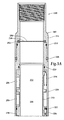
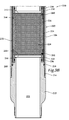
- Figures 2A-2B are cross sectional views of consecutive axial sections of a remote actuated downhole pressure barrier according to an embodiment of the present invention
- Figures 3A-3B are cross sectional views of consecutive axial sections of a remote actuated downhole pressure barrier according to an embodiment of the present invention
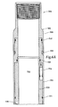
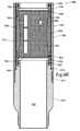
- Figures 4A-4B are cross sectional views of consecutive axial sections of a remote actuated downhole pressure barrier according to an embodiment of the present invention
- Figures 5A-5B are cross sectional views of consecutive axial sections of a remote actuated downhole pressure barrier according to an embodiment of the present invention.
- Figures 6A-6B are cross sectional views of consecutive axial sections of a remote actuated downhole pressure barrier according to an embodiment of the present invention.
- a remote actuated downhole pressure barrier being operated from an offshore oil and gas platform is schematically illustrated and generally designated 10.
- a semi-submersible platform 12 is centered over an offshore oil and gas formation 14 located below sea floor 16.
- a subsea conduit 18 extends from deck 20 of platform 12 to wellhead installation 22 including subsea blow-out preventers 24.
- Platform 12 has a hoisting apparatus 26 and a derrick 28 for raising and lowering pipe strings such as work string 30.
- a wellbore 32 extends through the various earth strata including formation 14.
- a casing 34 is cemented within wellbore 32 by cement 36.
- the portion of wellbore 32 extending through horizontal portion 38 includes a plurality of perforations 40 that allow fluid communication between formation 14 and wellbore 32.
- Work string 30 includes various tools such as a plurality of sand control screens 42, a remote actuated downhole pressure barrier 44 and a packer 46.
- remote actuated downhole pressure barrier 44 provides a pressure barrier that allows the operator to set production and isolation packers as well as pressure test the production tubing.
- remote actuated downhole pressure barrier 44 has been disposed in a horizontal portion of wellbore 32
- the remote actuated downhole pressure barriers of the present invention are equally well-suited for use in other well configurations including, but not limited to, inclined wells, wells with restrictions, non-deviated wells, multilateral wells and the like.
- use of directional terms such as “above”, “below”, “upper”, “lower” and the like are used for convenience in referring to the illustrations.
- the remote actuated downhole pressure barriers of the present invention are equally well-suited for use in onshore operations.
- Barrier 100 includes a generally tubular housing assembly 102.
- Housing assembly 102 that includes a top sub 104 that is securably and sealingly connected to a middle sub 106 by a plurality of set screws 108 and seal 110.
- middle sub 106 is securably and sealingly connected to a bottom sub 112 at threaded connection 114 and by seal 116.
- inner mandrel 118 Disposed within middle sub 106 is an inner mandrel 118. Seals 120, 121 provide a sealing relationship between middle sub 106 and inner mandrel 118.
- Housing assembly 102 has a flow passage 122 formed axially therethrough.
- housing assembly 102 is shown as being made up of several interconnected portions 104, 106, 112, 118, it is to be understood that greater or fewer numbers of housing portions may be utilized in the housing assembly 102 and the portions may be otherwise configured and otherwise attached to each other without departing from the principles of the present invention.
- Plug member 124 includes a dispersible portion 126 which is initially compacted within a plug sleeve 128.
- Plug member 124 is supported within housing assembly 102 by a pair of oppositely disposed retainer assemblies 130, 132.
- Retainer assembly 130 is sealingly coupled to inner mandrel 118 by a seal 134.
- Retainer assembly 132 is sealingly coupled to bottom sub 112 by a seal 136.
- Retainer assemblies 130, 132 are axially positioned between lower shoulder 138 of inner mandrel 118 and upper shoulder 140 of bottom sub 112.
- Retainer assemblies 130, 132 respectively include discoidal portions 142, 144 that are generally impervious and serve to isolate dispersible portion 126 from contact with any fluid in flow passage 122.
- Retainer assemblies 130, 132 including discoidal portions 142, 144 are preferable formed from a metal such as a stainless steel including, but not limited to, a 625 stainless steel.
- dispersible portion 126 is a compacted salt and sand composition which has sufficient compressive strength to resist fluid pressure in flow passage 122.
- an activating agent such as a wellbore fluid, water or other fluid
- the salt constituent will dissolve. This dissolving of the salt constituent significantly reduces the compressive strength of dispersible portion 126, so that it is no longer able to resist fluid pressure in flow passage 122.
- Plug member 124 may be dispersed by dissolving dispersible portion 126 or a constituent part thereof using wellbore fluid in flow passage 122. In certain implementations, however, a wellbore fluid capable of dispersing plug member 124 may not available, for example, if the fluid in flow passage 122 is salt-saturated, oil-based or otherwise incapable of dissolving a constituent part of dispersible portion 126.
- barrier 100 includes a fluid chamber 146 disposed within inner mandrel 118 and an upper portion of middle sub 106 and is protected from contamination with other fluids and debris in the well during conveyance by a debris barrier 148.
- Debris barrier 148 extends laterally across flow passage 122, thus isolating the fluid in fluid chamber 146 from contact with any other fluid or debris in flow passage 122 above debris barrier 148. As such, the fluid in fluid chamber 146 is available for interaction with dispersible portion 126 when desired.
- debris barrier 148 includes a body portion 150 extending across flow passage 122 and a somewhat enlarged annular-shaped peripheral portion 152 sealingly received between top sub 104 and middle sub 106 of housing assembly 102. Such sealing engagement of debris barrier 148 acts to completely isolate the fluid in fluid chamber 146 from other fluids in the well.
- Debris barrier 148 may be formed from an elastomeric material, however, in certain implementations, debris barrier 148 may alternatively be made of a nonelastomeric material. An elastomeric material is preferred, however, since applications of fluid pressure are made to flow passage 122 to initiate activation of plug member 124 as described below.
- barrier 100 includes an activating assembly that is operable to create a communication path through retainer assembly 130 to allow communication between the fluid in fluid chamber 146 and dispersible portion 126.
- the activating assembly includes an electronic package and a combustion assembly.
- the electronic package includes a pressure sensor 154, a logic module 156, batteries 158 and various signal and current conductors (not pictured).
- the combustion assembly includes ignition agents 160, 162 and combustible agents 164, 166.
- separator members 168, 170 are positioned respectively between combustible agents 164, 166 and dispersible portion 126.
- Separator members 168, 170 are preferable formed from a metal such as a stainless steel including, but not limited to, a 625 stainless steel.
- Heat shielding sleeve 172 is positioned between plug member 124 and middle sub 106.
- Heat shielding sleeve 172 is preferably formed from a ceramic materials or other material capable of shielding middle sub 106 from the heat and temperature generated in the combustion reaction discussed below.
- Pressure sensor 154 is operable to receive and interpret pressure signals sent from the surface. For example, by applying a predetermined number and sequence of fluid pressure fluctuations to flow passage 122 via the tubular string at the surface, pressure sensor 154 receives the signal via the fluid in fluid chamber 146. The pressure signals are transferred to the fluid in fluid chamber 146 from the fluid in the tubular string through debris barrier 148. When pressure sensor 154 receives the proper pressure signature, pressure sensor 154 sends a signal to logic module 156 to begin the activation process.
- the signal for initiating the activation of plug member 124 has been described as a pressure signal received by a pressure sensor, those skilled in the art will understand the other types of signals both wireless and wired could alternatively be used including, but not limited to, acoustic signals, electromagnetic signals, hydraulic signals, electrical signals, optical signals and the like, such signals being received and interpreted by the corresponding type of receiver.
- Logic module 156 receives the activation signal from pressure sensor 154 and causes a current to be sent to ignition agents 160, 162.
- Logic module 156 may include various controllers, processors, memory components, operating systems, instructions, communication protocols and the like. As should be understood by those skilled in the art, any of the functions described with reference to logic module 156 herein can be implemented using software, firmware, hardware, including fixed logic circuitry or a combination of these implementations. As such, the term logic module as used herein generally represents software, hardware or a combination of software and hardware.
- logic module represents program code and/or declarative content, e.g., markup language content that performs specified tasks when executed on a processing device or devices such as one or more processors or CPUs.
- the program code can be stored in one or more computer readable memory devices.
- the functionality of the illustrated logic module may be implemented as distinct units in separate physical grouping or can correspond to a conceptual allocation of different tasks performed by a single software program and/or hardware unit.
- Batteries 158 are used to power the electronic devices within barrier 100 such as pressure sensor 154 and logic module 156. In addition, batteries 158 are used to provide suitable current to initiate the combustion of combustible elements 164, 166. Batteries 158 may be of any suitable type such as alkaline batteries that provide sufficient power and current and are capable of withstanding the temperature in the well environment.
- ignition agents 160, 162 are metal burning fuses such as magnesium fuses which are activated by the electrical current supplied from batteries 158 in response to the activation signal.
- Metal fuses are preferred as metals burn without releasing cooling gases and can burn at extremely high temperatures. Magnesium fuses are most preferred as due to the reactive nature of magnesium and temperature at which magnesium burn which is sufficiently high to ignite combustible agents 164, 166.
- a nichrome wire such as a NiCr60 wire, may be used to directly ignite combustible agents 164, 166.
- a nichrome wire may be used in an ignition train to ignite a metal burning fuse which in turn ignites one of the combustible agents 164, 166. In this case, both the nichrome wire and the metal burning fuse may be considered to be one of the ignition agents 160, 162.
- Combustible agents 164, 166 are preferable formed from a composition of a metal powder and a metal oxide that produces an exothermic chemical reaction at high temperature such as a thermite reaction.
- the metal powder used in the composition may include aluminum, magnesium, calcium, titanium, zinc, silicon, boron and the like.
- the metal oxide used in the composition may include boron(III) oxide, silicon(IV) oxide, chromium(III) oxide, manganese(IV) oxide, iron(III) oxide, iron(II, III) oxide, copper(II) oxide, lead(II, III, IV) oxide and the like.
- a composition of aluminum and iron(III) oxide may be used which has a reaction according to the following equation:
- combustible agents 164, 166 that produce a thermite reaction is advantageous in the present invention as the reactants are stable at wellbore temperatures but produce an extremely intense exothermic reaction following ignition.
- the combination of the high temperature and the heat generated by the reaction are sufficient to melt both the metallic separator members 168, 170 and discoidal portions 142, 144 of retainer assemblies 130, 132.
- this process creates a communication path through retainer assembly 130 to allow communication between the fluid in fluid chamber 146 and dispersible portion 126.
- the fluid in fluid chamber 146 dissolves the salt in dispersible portion 126 such that the remaining sand component of dispersible portion 126 lacks sufficient compressive strength to plug flow passage 122. Accordingly, the sand disintegrates leaving an open bore within plug sleeve 128.
- Barrier 200 includes a generally tubular housing assembly 202 that includes a top sub 204 that is securably and sealingly connected to a middle sub 206 by a plurality of set screws 208 and seal 210. At its lower end, middle sub 206 is securably and sealingly connected to a bottom sub 212 at threaded connection 214 and by seal 216. Disposed within middle sub 206 is an inner mandrel 218. Seals 220, 221 provide a sealing relationship between middle sub 206 and inner mandrel 218. Housing assembly 202 has a flow passage 222 formed axially therethrough.
- Plug member 224 includes a dispersible portion 226 which is initially compacted within a plug sleeve 228.
- Plug member 224 is supported within housing assembly 202 by a pair of oppositely disposed retainer assemblies 230, 232.
- Retainer assembly 230 is sealingly coupled to inner mandrel 218 by a seal 234.
- Retainer assembly 232 is sealingly coupled to bottom sub 212 by a seal 236.
- Retainer assemblies 230, 232 are axially positioned between lower shoulder 238 of inner mandrel 218 and upper shoulder 240 of bottom sub 212.
- Retainer assemblies 230, 232 respectively include discoidal portions 242, 244 that are generally impervious and serve to isolate dispersible portion 226 from contact with any fluid in flow passage 222.
- dispersible portion 226 is preferably a compacted salt and sand composition, as described above.
- Barrier 200 includes a fluid chamber 246 disposed within inner mandrel 218 and an upper portion of middle sub 206 and is protected from contamination with other fluids and debris by a debris barrier 248.
- Debris barrier 248 includes a body portion 250 extending across flow passage 222 and a somewhat enlarged annular-shaped peripheral portion 252 sealingly received between top sub 204 and middle sub 206 of housing assembly 202.
- barrier 200 includes an activating assembly that is operable to create a communication path through retainer assembly 230 to allow communication between the fluid in fluid chamber 246 and dispersible portion 226.
- the activating assembly includes an electronic package and a combustion assembly.
- the electronic package includes a pressure sensor 254, a logic module 256, batteries 258 and various signal and current conductors (not pictured).
- the combustion assembly includes ignition agents 260, 262 and combustible agents 264, 266.
- combustible agents 264, 266 are integrally disposed within dispersible portion 226 such that the greatest concentration of the combustible agents 264, 266 is located in the two ends of dispersible portion 226 proximate discoidal portions 242, 244 of retainer assemblies 230, 232.
- Ignition agents 260, 262 are preferably metal fuses, as described above.
- Combustible agents 264, 266 are preferably formed from a composition of a metal powder and a metal oxide, as described above.
- An optional heat shielding sleeve 272 is positioned between plug member 224 and middle sub 206.
- pressure sensor 254 receives and interprets pressure signals sent from the surface. When pressure sensor 254 receives the proper pressure signature, pressure sensor 254 sends a signal to logic module 256 to begin the activation process. Logic module 256 then causes a current to be sent to ignition agents 260, 262 from batteries 258. The current is used to ignite ignition agents 260, 262 which in turn ignite combustible agents 264, 266. The combination of the high temperature and the heat generated by the reaction of combustible agents 264, 266 are sufficient to melt discoidal portions 242, 244 of retainer assemblies 230, 232, which creates a communication path through retainer assembly 230 to allow communication between the fluid in fluid chamber 246 and dispersible portion 226.
- the fluid in fluid chamber 246 dissolves the salt in dispersible portion 226 such that the remaining sand component of dispersible portion 226 lacks sufficient compressive strength to plug flow passage 222. Accordingly, the sand disintegrates leaving an open bore within plug sleeve 228.
- Barrier 300 includes a generally tubular housing assembly 302 that includes a top sub 304 that is securably and sealingly connected to a middle sub 306 by a plurality of set screws 308 and seal 310. At its lower end, middle sub 306 is securably and sealingly connected to a bottom sub 312 at threaded connection 314 and by seal 316. Disposed within middle sub 306 is an inner mandrel 318. Seals 320, 321 provide a sealing relationship between middle sub 306 and inner mandrel 318. Housing assembly 302 has a flow passage 322 formed axially therethrough.
- Plug member 324 includes a removable portion 326 which is initially compacted within a plug sleeve 328.
- Plug member 324 is supported within housing assembly 302 by a pair of oppositely disposed retainer assemblies 330, 332.
- Retainer assembly 330 is sealingly coupled to inner mandrel 318 by a seal 334.
- Retainer assembly 332 is sealingly coupled to bottom sub 312 by a seal 336.
- Retainer assemblies 330, 332 are axially positioned between lower shoulder 338 of inner mandrel 318 and upper shoulder 340 of bottom sub 312.
- Retainer assemblies 330, 332 respectively include discoidal portions 342, 344 that are generally impervious and serve to isolate removable portion 326 from contact with any fluid in flow passage 322.
- removable portion 326 may be a compacted salt and sand composition, as described above, that is generally uniformly mixed with a combustible agent 364.
- barrier 300 includes a fluid chamber 346 disposed within inner mandrel 318 and an upper portion of middle sub 306 and is protected from contamination with other fluids and debris by a debris barrier 348.
- Debris barrier 348 includes a body portion 350 extending across flow passage 322 and a somewhat enlarged annular-shaped peripheral portion 352 sealingly received between top sub 304 and middle sub 306 of housing assembly 302.
- removable portion 326 may be substantially completely formed from a compaction of the combustible agent 364.
- fluid chamber 346 and debris barrier 348 are optional.
- barrier 300 includes an activating assembly that is operable to create a communication path through retainer assembly 330 to allow communication between the fluid in fluid chamber 346 and removable portion 326.
- the activating assembly includes an electronic package and a combustion assembly.
- the electronic package includes a pressure sensor 354, a logic module 356, batteries 358 and various signal and current conductors (not pictured).
- the combustion assembly includes a plurality of ignition agents, only two of which, ignition agents 360, 362 are shown and combustible agent 364.
- the ignition agents are preferably metal fuses, as described above.
- Combustible agent 364 is preferably formed from a composition of a metal powder and a metal oxide, as described above.
- An optional heat shielding sleeve 372 is positioned between plug member 324 and middle sub 306.
- pressure sensor 354 receives and interprets pressure signals sent from the surface. When pressure sensor 354 receives the proper pressure signature, pressure sensor 354 sends a signal to logic module 356 to begin the activation process. Logic module 356 then causes a current to be sent to the ignition agents from batteries 358. The current is used to ignite the ignition agents, which in turn ignites combustible agent 364. The combination of the high temperature and the heat generated by the reaction of combustible agent 364 is sufficient to melt discoidal portions 342, 344 of retainer assemblies 330, 332. In those embodiments including fluid chamber 346 and wherein removable portion 326 includes a salt constituent, a communication path is created through retainer assembly 330 to allow communication between the fluid in fluid chamber 346 and removable portion 326.
- the fluid in fluid chamber 346 dissolves the salt in removable portion 326 such that the remaining sand component of removable portion 326 lacks sufficient compressive strength to plug flow passage 322. Accordingly, the sand disintegrates leaving an open bore within plug sleeve 328.
- removable portion 326 is substantially completely formed from a compaction of the combustible agent 364, combustion of combustible agent 364 not only melts the discoidal portions 342, 344 of retainer assemblies 330, 332 but also creates the open bore within plug sleeve 328.
- Barrier 400 includes a generally tubular housing assembly 402 that includes a top sub 404 that is securably and sealingly connected to a middle sub 406 by a plurality of set screws 408 and seal 410. At its lower end, middle sub 406 is securably and sealingly connected to a bottom sub 412 at threaded connection 414 and by seal 416. Disposed within middle sub 406 is an inner mandrel 418. Seals 420, 421 provide a sealing relationship between middle sub 406 and inner mandrel 418. Housing assembly 402 has a flow passage 422 formed axially therethrough.
- Plug member 424 includes a removable portion 426 which is initially positioned within a plug sleeve 428.
- Plug member 424 is supported within housing assembly 402 by a pair of oppositely disposed retainer assemblies 430, 432.
- Retainer assembly 430 is sealingly coupled to inner mandrel 418 by a seal 434.
- Retainer assembly 432 is sealingly coupled to bottom sub 412 by a seal 436.
- Retainer assemblies 430, 432 are axially positioned between lower shoulder 438 of inner mandrel 418 and upper shoulder 440 of bottom sub 412.
- Retainer assemblies 430, 432 respectively include discoidal portions 442, 444 that are generally impervious and serve to isolate removable portion 426 from contact with any fluid in flow passage 422.
- removable portion 426 is preferably a polymer material such as a thermosetting polymer including, but not limited to, an epoxy.
- Barrier 400 includes an activating assembly that is operable to create a communication path through passage 422.
- the activating assembly includes an electronic package and a combustion assembly.
- the electronic package includes a pressure sensor 454, a logic module 456, batteries 458 and various signal and current conductors (not pictured).
- the combustion assembly includes a plurality of ignition agents, only two of which, ignition agents 460, 462 are shown and combustible agent 464.
- combustible agent 464 is integrally disposed within removable portion 426 in a substantially even distribution throughout removable portion 426.
- the ignition agents are preferably metal fuses, as described above.
- Combustible agent 464 is preferably formed from a composition of a metal powder and a metal oxide, as described above.
- An optional heat shielding sleeve 472 is positioned between plug member 424 and middle sub 406.
- pressure sensor 454 receives and interprets pressure signals sent from the surface. When pressure sensor 454 receives the proper pressure signature, pressure sensor 454 sends a signal to logic module 456 to begin the activation process. Logic module 456 then causes a current to be sent to the ignition agents from batteries 458. The current is used to ignite the ignition agents, which in turn ignites combustible agent 464. The combination of the high temperature and the heat generated by the reaction of combustible agent 464 is sufficient to melt discoidal portions 442, 444 of retainer assemblies 430, 432 as well as the matrix material of removable portion 426 leaving an open bore within plug sleeve 428.
- Barrier 500 includes a generally tubular housing assembly 502 that includes a top sub 504 that is securably and sealingly connected to a middle sub 506 by a plurality of set screws 508 and seal 510. At its lower end, middle sub 506 is securably and sealingly connected to a bottom sub 512 at threaded connection 514 and by seal 516. Disposed within middle sub 506 is an inner mandrel 518. Seals 520, 521 provide a sealing relationship between middle sub 506 and inner mandrel 518. Housing assembly 502 has a flow passage 522 formed axially therethrough.
- Plug member 524 includes a removable portion 526 which is initially positioned within a plug sleeve 528.
- Plug member 524 is supported within housing assembly 502 by a pair of oppositely disposed retainer assemblies 530, 532.
- Retainer assembly 530 is sealingly coupled to inner mandrel 518 by a seal 534.
- Retainer assembly 532 is sealingly coupled to bottom sub 512 by a seal 536.
- Retainer assemblies 530, 532 are axially positioned between lower shoulder 538 of inner mandrel 518 and upper shoulder 540 of bottom sub 512.
- Retainer assemblies 530, 532 respectively include discoidal portions 542, 544 that are generally impervious and serve to isolate removable portion 526 from contact with any fluid in flow passage 522.
- removable portion 526 is preferably a polymer material such as a thermosetting polymer including, but not limited to, an epoxy.
- Barrier 500 includes an activating assembly that is operable to create a communication path through passage 522.
- the activating assembly includes an electronic package and a combustion assembly.
- the electronic package includes a pressure sensor 554, a logic module 556, batteries 558 and various signal and current conductors (not pictured). As illustrated, portions of the electronic package are positioned within removable portion 526. In other implementations, all of the components of the electronic package could be positioned within removable portion 526.
- the combustion assembly includes a plurality of ignition agents, only two of which, ignition agents 560, 562 are shown and combustible agent 564. In the illustrated embodiment, combustible agent 564 is integrally disposed within removable portion 526 in a substantially even distribution throughout removable portion 526.
- the ignition agents are preferably metal fuses, as described above.
- Combustible agent 564 is preferably formed from a composition of a metal powder and a metal oxide, as described above.
- An optional heat shielding sleeve 572 is positioned between plug member 524 and middle sub 506.
- pressure sensor 554 receives and interprets pressure signals sent from the surface. When pressure sensor 554 receives the proper pressure signature, pressure sensor 554 sends a signal to logic module 556 to begin the activation process. Logic module 556 then causes a current to be sent to the ignition agents from batteries 558. The current is used to ignite the ignition agents, which in turn ignites combustible agent 564. The combination of the high temperature and the heat generated by the reaction of combustible agent 564 is sufficient to melt discoidal portions 542, 544 of retainer assemblies 530, 532 as well as the matrix material of removable portion 526 leaving an open bore within plug sleeve 528.
Landscapes
- Life Sciences & Earth Sciences (AREA)
- Mining & Mineral Resources (AREA)
- Geology (AREA)
- Engineering & Computer Science (AREA)
- Physics & Mathematics (AREA)
- Chemical & Material Sciences (AREA)
- Environmental & Geological Engineering (AREA)
- Fluid Mechanics (AREA)
- General Chemical & Material Sciences (AREA)
- Chemical Kinetics & Catalysis (AREA)
- General Life Sciences & Earth Sciences (AREA)
- Geochemistry & Mineralogy (AREA)
- Fuel Cell (AREA)
Applications Claiming Priority (1)
| Application Number | Priority Date | Filing Date | Title |
|---|---|---|---|
| US12/544,318 US20110042099A1 (en) | 2009-08-20 | 2009-08-20 | Remote Actuated Downhole Pressure Barrier and Method for Use of Same |
Publications (1)
| Publication Number | Publication Date |
|---|---|
| EP2295710A2 true EP2295710A2 (fr) | 2011-03-16 |
Family
ID=42782219
Family Applications (1)
| Application Number | Title | Priority Date | Filing Date |
|---|---|---|---|
| EP10173537A Withdrawn EP2295710A2 (fr) | 2009-08-20 | 2010-08-20 | Barrière contre la pression de trou de forage actionnée à distance et son procédé d'utilisation |
Country Status (2)
| Country | Link |
|---|---|
| US (1) | US20110042099A1 (fr) |
| EP (1) | EP2295710A2 (fr) |
Families Citing this family (25)
| Publication number | Priority date | Publication date | Assignee | Title |
|---|---|---|---|---|
| US8276670B2 (en) * | 2009-04-27 | 2012-10-02 | Schlumberger Technology Corporation | Downhole dissolvable plug |
| US9441446B2 (en) | 2012-08-31 | 2016-09-13 | Halliburton Energy Services, Inc. | Electronic rupture discs for interventionaless barrier plug |
| US9650858B2 (en) | 2013-02-26 | 2017-05-16 | Halliburton Energy Services, Inc. | Resettable packer assembly and methods of using the same |
| US9441437B2 (en) | 2013-05-16 | 2016-09-13 | Halliburton Energy Services, Inc. | Electronic rupture discs for interventionless barrier plug |
| US10316611B2 (en) | 2016-08-24 | 2019-06-11 | Kevin David Wutherich | Hybrid bridge plug |
| GB2581880A (en) | 2017-11-20 | 2020-09-02 | Halliburton Energy Services Inc | Full bore buoyancy assisted casing system |
| WO2020117229A1 (fr) | 2018-12-05 | 2020-06-11 | Halliburton Energy Services, Inc. | Appareil de fond de trou |
| WO2020131076A1 (fr) | 2018-12-20 | 2020-06-25 | Halliburtion Energy Services, Inc. | Outil d'aide à la flottabilité |
| US11293261B2 (en) | 2018-12-21 | 2022-04-05 | Halliburton Energy Services, Inc. | Buoyancy assist tool |
| US11603736B2 (en) | 2019-04-15 | 2023-03-14 | Halliburton Energy Services, Inc. | Buoyancy assist tool with degradable nose |
| US11492867B2 (en) | 2019-04-16 | 2022-11-08 | Halliburton Energy Services, Inc. | Downhole apparatus with degradable plugs |
| WO2020226655A1 (fr) | 2019-05-09 | 2020-11-12 | Halliburton Energy Services, Inc. | Appareil de fond de trou avec bouchons amovibles |
| WO2021021211A1 (fr) * | 2019-08-01 | 2021-02-04 | Halliburton Energy Services, Inc. | Barrière de piston obturateur |
| US11499395B2 (en) | 2019-08-26 | 2022-11-15 | Halliburton Energy Services, Inc. | Flapper disk for buoyancy assisted casing equipment |
| US11105166B2 (en) | 2019-08-27 | 2021-08-31 | Halliburton Energy Services, Inc. | Buoyancy assist tool with floating piston |
| US11072990B2 (en) | 2019-10-25 | 2021-07-27 | Halliburton Energy Services, Inc. | Buoyancy assist tool with overlapping membranes |
| US10995583B1 (en) * | 2019-10-31 | 2021-05-04 | Halliburton Energy Services, Inc. | Buoyancy assist tool with debris barrier |
| US10989013B1 (en) | 2019-11-20 | 2021-04-27 | Halliburton Energy Services, Inc. | Buoyancy assist tool with center diaphragm debris barrier |
| US11230905B2 (en) * | 2019-12-03 | 2022-01-25 | Halliburton Energy Services, Inc. | Buoyancy assist tool with waffle debris barrier |
| US11639641B2 (en) * | 2019-12-17 | 2023-05-02 | Klx Energy Services, Llc | Degradable in-line buoyant system for running casing in a wellbore |
| US11142994B2 (en) | 2020-02-19 | 2021-10-12 | Halliburton Energy Services, Inc. | Buoyancy assist tool with annular cavity and piston |
| US11293252B2 (en) * | 2020-04-16 | 2022-04-05 | Halliburton Energy Services, Inc. | Fluid barriers for dissolvable plugs |
| US11359454B2 (en) | 2020-06-02 | 2022-06-14 | Halliburton Energy Services, Inc. | Buoyancy assist tool with annular cavity and piston |
| US12078026B2 (en) | 2022-12-13 | 2024-09-03 | Forum Us, Inc. | Wiper plug with dissolvable core |
| US12221851B1 (en) | 2023-11-16 | 2025-02-11 | Forum Us, Inc. | Pump down wiper plug assembly |
Family Cites Families (25)
| Publication number | Priority date | Publication date | Assignee | Title |
|---|---|---|---|---|
| US5765641A (en) * | 1994-05-02 | 1998-06-16 | Halliburton Energy Services, Inc. | Bidirectional disappearing plug |
| US6026903A (en) * | 1994-05-02 | 2000-02-22 | Halliburton Energy Services, Inc. | Bidirectional disappearing plug |
| US5826661A (en) * | 1994-05-02 | 1998-10-27 | Halliburton Energy Services, Inc. | Linear indexing apparatus and methods of using same |
| US5479986A (en) * | 1994-05-02 | 1996-01-02 | Halliburton Company | Temporary plug system |
| US5607017A (en) * | 1995-07-03 | 1997-03-04 | Pes, Inc. | Dissolvable well plug |
| US5947205A (en) * | 1996-06-20 | 1999-09-07 | Halliburton Energy Services, Inc. | Linear indexing apparatus with selective porting |
| US6059038A (en) * | 1998-02-26 | 2000-05-09 | Halliburton Energy Services, Inc. | Auto-fill sub |
| US6076600A (en) * | 1998-02-27 | 2000-06-20 | Halliburton Energy Services, Inc. | Plug apparatus having a dispersible plug member and a fluid barrier |
| US6161622A (en) * | 1998-11-02 | 2000-12-19 | Halliburton Energy Services, Inc. | Remote actuated plug method |
| US6220350B1 (en) * | 1998-12-01 | 2001-04-24 | Halliburton Energy Services, Inc. | High strength water soluble plug |
| US6925937B2 (en) * | 2001-09-19 | 2005-08-09 | Michael C. Robertson | Thermal generator for downhole tools and methods of igniting and assembly |
| NO322871B1 (no) * | 2002-11-20 | 2006-12-18 | Tco As | Fjernstyrt tennmekanisme for bruk i vaeskefylte ror eller borehull |
| US6926086B2 (en) * | 2003-05-09 | 2005-08-09 | Halliburton Energy Services, Inc. | Method for removing a tool from a well |
| US7044230B2 (en) * | 2004-01-27 | 2006-05-16 | Halliburton Energy Services, Inc. | Method for removing a tool from a well |
| US7210533B2 (en) * | 2004-02-11 | 2007-05-01 | Halliburton Energy Services, Inc. | Disposable downhole tool with segmented compression element and method |
| US7168494B2 (en) * | 2004-03-18 | 2007-01-30 | Halliburton Energy Services, Inc. | Dissolvable downhole tools |
| US7353879B2 (en) * | 2004-03-18 | 2008-04-08 | Halliburton Energy Services, Inc. | Biodegradable downhole tools |
| US7513311B2 (en) * | 2006-04-28 | 2009-04-07 | Weatherford/Lamb, Inc. | Temporary well zone isolation |
| US20070284114A1 (en) * | 2006-06-08 | 2007-12-13 | Halliburton Energy Services, Inc. | Method for removing a consumable downhole tool |
| US7591318B2 (en) * | 2006-07-20 | 2009-09-22 | Halliburton Energy Services, Inc. | Method for removing a sealing plug from a well |
| GB0618687D0 (en) * | 2006-09-22 | 2006-11-01 | Omega Completion Technology | Erodeable pressure barrier |
| NO329454B1 (no) * | 2007-04-17 | 2010-10-25 | Tco As | Testplugg. |
| US8235103B2 (en) * | 2009-01-14 | 2012-08-07 | Halliburton Energy Services, Inc. | Well tools incorporating valves operable by low electrical power input |
| US8276670B2 (en) * | 2009-04-27 | 2012-10-02 | Schlumberger Technology Corporation | Downhole dissolvable plug |
| US8322426B2 (en) * | 2010-04-28 | 2012-12-04 | Halliburton Energy Services, Inc. | Downhole actuator apparatus having a chemically activated trigger |
-
2009
- 2009-08-20 US US12/544,318 patent/US20110042099A1/en not_active Abandoned
-
2010
- 2010-08-20 EP EP10173537A patent/EP2295710A2/fr not_active Withdrawn
Non-Patent Citations (1)
| Title |
|---|
| None |
Also Published As
| Publication number | Publication date |
|---|---|
| US20110042099A1 (en) | 2011-02-24 |
Similar Documents
| Publication | Publication Date | Title |
|---|---|---|
| US20110042099A1 (en) | Remote Actuated Downhole Pressure Barrier and Method for Use of Same | |
| US7168494B2 (en) | Dissolvable downhole tools | |
| US9033046B2 (en) | Multi-zone fracturing and sand control completion system and method thereof | |
| AU2011341562B2 (en) | Autonomous downhole conveyance system | |
| US8272446B2 (en) | Method for removing a consumable downhole tool | |
| EP2044288B1 (fr) | Procédé pour retirer un bouchon de fermeture étanche d'un puits | |
| CA2466223C (fr) | Methode d'enlevement d'un outil d'un puits | |
| US9447654B2 (en) | Downhole circulating valve having a seal plug and method for operating same | |
| US20120055666A1 (en) | Consumable downhole tools | |
| US20040216632A1 (en) | Detonating cord interrupt device and method for transporting an explosive device | |
| CA3036129C (fr) | Agent propulseur commande electriquement dans des operations souterraines et equipement | |
| CA2564190C (fr) | Packer concentrique installe hydrauliquement et comportant une derivation ombilicale multiple a travers le piston | |
| US20050067163A1 (en) | Monobore release for tubing conveyed perforating |
Legal Events
| Date | Code | Title | Description |
|---|---|---|---|
| PUAI | Public reference made under article 153(3) epc to a published international application that has entered the european phase |
Free format text: ORIGINAL CODE: 0009012 |
|
| AK | Designated contracting states |
Kind code of ref document: A2 Designated state(s): AL AT BE BG CH CY CZ DE DK EE ES FI FR GB GR HR HU IE IS IT LI LT LU LV MC MK MT NL NO PL PT RO SE SI SK SM TR |
|
| AX | Request for extension of the european patent |
Extension state: BA ME RS |
|
| STAA | Information on the status of an ep patent application or granted ep patent |
Free format text: STATUS: THE APPLICATION IS DEEMED TO BE WITHDRAWN |
|
| 18D | Application deemed to be withdrawn |
Effective date: 20160301 |