EP2295717A2 - Bohrlochfilteranordnung - Google Patents
Bohrlochfilteranordnung Download PDFInfo
- Publication number
- EP2295717A2 EP2295717A2 EP10172541A EP10172541A EP2295717A2 EP 2295717 A2 EP2295717 A2 EP 2295717A2 EP 10172541 A EP10172541 A EP 10172541A EP 10172541 A EP10172541 A EP 10172541A EP 2295717 A2 EP2295717 A2 EP 2295717A2
- Authority
- EP
- European Patent Office
- Prior art keywords
- rigid member
- base pipe
- screen assembly
- openings
- swellable material
- Prior art date
- Legal status (The legal status is an assumption and is not a legal conclusion. Google has not performed a legal analysis and makes no representation as to the accuracy of the status listed.)
- Withdrawn
Links
- 239000000463 material Substances 0.000 claims abstract description 135
- 239000012530 fluid Substances 0.000 claims abstract description 113
- 229930195733 hydrocarbon Natural products 0.000 claims abstract description 46
- 150000002430 hydrocarbons Chemical class 0.000 claims abstract description 46
- 239000004215 Carbon black (E152) Substances 0.000 claims abstract description 44
- 238000004891 communication Methods 0.000 claims abstract description 28
- 230000003213 activating effect Effects 0.000 claims description 28
- 230000008961 swelling Effects 0.000 claims description 26
- 229920000642 polymer Polymers 0.000 claims description 20
- XLYOFNOQVPJJNP-UHFFFAOYSA-N water Substances O XLYOFNOQVPJJNP-UHFFFAOYSA-N 0.000 claims description 15
- 229920001971 elastomer Polymers 0.000 claims description 14
- 239000005060 rubber Substances 0.000 claims description 13
- 238000001914 filtration Methods 0.000 claims description 10
- 229910052751 metal Inorganic materials 0.000 claims description 10
- 239000002184 metal Substances 0.000 claims description 10
- 239000002131 composite material Substances 0.000 claims description 6
- 230000004044 response Effects 0.000 claims description 6
- 150000001875 compounds Chemical class 0.000 claims description 4
- 210000003734 kidney Anatomy 0.000 claims description 3
- 230000000712 assembly Effects 0.000 abstract description 36
- 238000000429 assembly Methods 0.000 abstract description 36
- 238000004519 manufacturing process Methods 0.000 abstract description 21
- 230000015572 biosynthetic process Effects 0.000 description 34
- 238000005755 formation reaction Methods 0.000 description 34
- 239000011236 particulate material Substances 0.000 description 13
- 239000000178 monomer Substances 0.000 description 10
- 239000004576 sand Substances 0.000 description 10
- -1 hydroxyethyl acylate Chemical compound 0.000 description 9
- 150000003839 salts Chemical class 0.000 description 8
- XEEYBQQBJWHFJM-UHFFFAOYSA-N Iron Chemical compound [Fe] XEEYBQQBJWHFJM-UHFFFAOYSA-N 0.000 description 6
- PXHVJJICTQNCMI-UHFFFAOYSA-N Nickel Chemical compound [Ni] PXHVJJICTQNCMI-UHFFFAOYSA-N 0.000 description 6
- 229910000831 Steel Inorganic materials 0.000 description 5
- 239000007789 gas Substances 0.000 description 5
- 238000002347 injection Methods 0.000 description 5
- 239000007924 injection Substances 0.000 description 5
- 238000000034 method Methods 0.000 description 5
- 239000010959 steel Substances 0.000 description 5
- 229910001369 Brass Inorganic materials 0.000 description 3
- 229910000906 Bronze Inorganic materials 0.000 description 3
- RYGMFSIKBFXOCR-UHFFFAOYSA-N Copper Chemical compound [Cu] RYGMFSIKBFXOCR-UHFFFAOYSA-N 0.000 description 3
- XEKOWRVHYACXOJ-UHFFFAOYSA-N Ethyl acetate Chemical compound CCOC(C)=O XEKOWRVHYACXOJ-UHFFFAOYSA-N 0.000 description 3
- RTAQQCXQSZGOHL-UHFFFAOYSA-N Titanium Chemical compound [Ti] RTAQQCXQSZGOHL-UHFFFAOYSA-N 0.000 description 3
- 125000000217 alkyl group Chemical group 0.000 description 3
- 239000010951 brass Substances 0.000 description 3
- 239000010974 bronze Substances 0.000 description 3
- 125000004432 carbon atom Chemical group C* 0.000 description 3
- 239000010941 cobalt Substances 0.000 description 3
- 229910017052 cobalt Inorganic materials 0.000 description 3
- GUTLYIVDDKVIGB-UHFFFAOYSA-N cobalt atom Chemical compound [Co] GUTLYIVDDKVIGB-UHFFFAOYSA-N 0.000 description 3
- 239000010949 copper Substances 0.000 description 3
- 229910052802 copper Inorganic materials 0.000 description 3
- KUNSUQLRTQLHQQ-UHFFFAOYSA-N copper tin Chemical compound [Cu].[Sn] KUNSUQLRTQLHQQ-UHFFFAOYSA-N 0.000 description 3
- 239000000835 fiber Substances 0.000 description 3
- 238000009434 installation Methods 0.000 description 3
- 229910052742 iron Inorganic materials 0.000 description 3
- 150000002739 metals Chemical class 0.000 description 3
- 229910052759 nickel Inorganic materials 0.000 description 3
- 238000012856 packing Methods 0.000 description 3
- 230000000717 retained effect Effects 0.000 description 3
- 239000010936 titanium Substances 0.000 description 3
- 229910052719 titanium Inorganic materials 0.000 description 3
- WFKWXMTUELFFGS-UHFFFAOYSA-N tungsten Chemical compound [W] WFKWXMTUELFFGS-UHFFFAOYSA-N 0.000 description 3
- 239000010937 tungsten Substances 0.000 description 3
- 229910052721 tungsten Inorganic materials 0.000 description 3
- SSONCJTVDRSLNK-UHFFFAOYSA-N 2-methylprop-2-enoic acid;hydrochloride Chemical compound Cl.CC(=C)C(O)=O SSONCJTVDRSLNK-UHFFFAOYSA-N 0.000 description 2
- 229920002943 EPDM rubber Polymers 0.000 description 2
- 238000010521 absorption reaction Methods 0.000 description 2
- 229920001577 copolymer Polymers 0.000 description 2
- 230000002209 hydrophobic effect Effects 0.000 description 2
- 238000002955 isolation Methods 0.000 description 2
- 230000007246 mechanism Effects 0.000 description 2
- 239000012528 membrane Substances 0.000 description 2
- 239000000203 mixture Substances 0.000 description 2
- 239000002002 slurry Substances 0.000 description 2
- SMZOUWXMTYCWNB-UHFFFAOYSA-N 2-(2-methoxy-5-methylphenyl)ethanamine Chemical compound COC1=CC=C(C)C=C1CCN SMZOUWXMTYCWNB-UHFFFAOYSA-N 0.000 description 1
- 229920000536 2-Acrylamido-2-methylpropane sulfonic acid Polymers 0.000 description 1
- XHZPRMZZQOIPDS-UHFFFAOYSA-N 2-Methyl-2-[(1-oxo-2-propenyl)amino]-1-propanesulfonic acid Chemical compound OS(=O)(=O)CC(C)(C)NC(=O)C=C XHZPRMZZQOIPDS-UHFFFAOYSA-N 0.000 description 1
- NIXOWILDQLNWCW-UHFFFAOYSA-N 2-Propenoic acid Natural products OC(=O)C=C NIXOWILDQLNWCW-UHFFFAOYSA-N 0.000 description 1
- SSBZCVSVYYREGU-UHFFFAOYSA-N 2-methylprop-2-enoic acid hydroiodide Chemical compound I.CC(=C)C(O)=O SSBZCVSVYYREGU-UHFFFAOYSA-N 0.000 description 1
- FLCAEMBIQVZWIF-UHFFFAOYSA-N 6-(dimethylamino)-2-methylhex-2-enamide Chemical compound CN(C)CCCC=C(C)C(N)=O FLCAEMBIQVZWIF-UHFFFAOYSA-N 0.000 description 1
- HRPVXLWXLXDGHG-UHFFFAOYSA-N Acrylamide Chemical compound NC(=O)C=C HRPVXLWXLXDGHG-UHFFFAOYSA-N 0.000 description 1
- NLHHRLWOUZZQLW-UHFFFAOYSA-N Acrylonitrile Chemical compound C=CC#N NLHHRLWOUZZQLW-UHFFFAOYSA-N 0.000 description 1
- 244000043261 Hevea brasiliensis Species 0.000 description 1
- CERQOIWHTDAKMF-UHFFFAOYSA-M Methacrylate Chemical compound CC(=C)C([O-])=O CERQOIWHTDAKMF-UHFFFAOYSA-M 0.000 description 1
- VVQNEPGJFQJSBK-UHFFFAOYSA-N Methyl methacrylate Chemical compound COC(=O)C(C)=C VVQNEPGJFQJSBK-UHFFFAOYSA-N 0.000 description 1
- WHNWPMSKXPGLAX-UHFFFAOYSA-N N-Vinyl-2-pyrrolidone Chemical compound C=CN1CCCC1=O WHNWPMSKXPGLAX-UHFFFAOYSA-N 0.000 description 1
- 229920000459 Nitrile rubber Polymers 0.000 description 1
- 239000005062 Polybutadiene Substances 0.000 description 1
- 239000002174 Styrene-butadiene Substances 0.000 description 1
- 230000006978 adaptation Effects 0.000 description 1
- 125000005250 alkyl acrylate group Chemical group 0.000 description 1
- 230000000903 blocking effect Effects 0.000 description 1
- MTAZNLWOLGHBHU-UHFFFAOYSA-N butadiene-styrene rubber Chemical compound C=CC=C.C=CC1=CC=CC=C1 MTAZNLWOLGHBHU-UHFFFAOYSA-N 0.000 description 1
- 229920002678 cellulose Polymers 0.000 description 1
- 239000001913 cellulose Substances 0.000 description 1
- 239000011248 coating agent Substances 0.000 description 1
- 238000000576 coating method Methods 0.000 description 1
- 239000000806 elastomer Substances 0.000 description 1
- HQQADJVZYDDRJT-UHFFFAOYSA-N ethene;prop-1-ene Chemical group C=C.CC=C HQQADJVZYDDRJT-UHFFFAOYSA-N 0.000 description 1
- 229940093499 ethyl acetate Drugs 0.000 description 1
- 235000019439 ethyl acetate Nutrition 0.000 description 1
- 239000008398 formation water Substances 0.000 description 1
- 229920001600 hydrophobic polymer Polymers 0.000 description 1
- 229920003049 isoprene rubber Polymers 0.000 description 1
- 239000010410 layer Substances 0.000 description 1
- 239000007788 liquid Substances 0.000 description 1
- 239000000320 mechanical mixture Substances 0.000 description 1
- FQPSGWSUVKBHSU-UHFFFAOYSA-N methacrylamide Chemical compound CC(=C)C(N)=O FQPSGWSUVKBHSU-UHFFFAOYSA-N 0.000 description 1
- 238000012986 modification Methods 0.000 description 1
- 230000004048 modification Effects 0.000 description 1
- 229940088644 n,n-dimethylacrylamide Drugs 0.000 description 1
- YLGYACDQVQQZSW-UHFFFAOYSA-N n,n-dimethylprop-2-enamide Chemical compound CN(C)C(=O)C=C YLGYACDQVQQZSW-UHFFFAOYSA-N 0.000 description 1
- 229920003052 natural elastomer Polymers 0.000 description 1
- 229920001194 natural rubber Polymers 0.000 description 1
- 229920001084 poly(chloroprene) Polymers 0.000 description 1
- 229920001200 poly(ethylene-vinyl acetate) Polymers 0.000 description 1
- 229920000636 poly(norbornene) polymer Polymers 0.000 description 1
- 229920002401 polyacrylamide Polymers 0.000 description 1
- 229920002857 polybutadiene Polymers 0.000 description 1
- 238000006116 polymerization reaction Methods 0.000 description 1
- 230000000379 polymerizing effect Effects 0.000 description 1
- 229920000193 polymethacrylate Polymers 0.000 description 1
- 229920000915 polyvinyl chloride Polymers 0.000 description 1
- 239000004800 polyvinyl chloride Substances 0.000 description 1
- 230000008569 process Effects 0.000 description 1
- 238000005086 pumping Methods 0.000 description 1
- 238000012552 review Methods 0.000 description 1
- 230000006641 stabilisation Effects 0.000 description 1
- 238000011105 stabilization Methods 0.000 description 1
- 230000000087 stabilizing effect Effects 0.000 description 1
- 239000011115 styrene butadiene Substances 0.000 description 1
- 229920003048 styrene butadiene rubber Polymers 0.000 description 1
- 239000000725 suspension Substances 0.000 description 1
Images


Classifications
-
- E—FIXED CONSTRUCTIONS
- E21—EARTH OR ROCK DRILLING; MINING
- E21B—EARTH OR ROCK DRILLING; OBTAINING OIL, GAS, WATER, SOLUBLE OR MELTABLE MATERIALS OR A SLURRY OF MINERALS FROM WELLS
- E21B43/00—Methods or apparatus for obtaining oil, gas, water, soluble or meltable materials or a slurry of minerals from wells
- E21B43/02—Subsoil filtering
- E21B43/08—Screens or liners
-
- E—FIXED CONSTRUCTIONS
- E21—EARTH OR ROCK DRILLING; MINING
- E21B—EARTH OR ROCK DRILLING; OBTAINING OIL, GAS, WATER, SOLUBLE OR MELTABLE MATERIALS OR A SLURRY OF MINERALS FROM WELLS
- E21B43/00—Methods or apparatus for obtaining oil, gas, water, soluble or meltable materials or a slurry of minerals from wells
- E21B43/02—Subsoil filtering
- E21B43/10—Setting of casings, screens, liners or the like in wells
- E21B43/103—Setting of casings, screens, liners or the like in wells of expandable casings, screens, liners, or the like
Definitions
- the present invention relates generally to control screens for subterranean fluid production and, more particularly (although not necessarily exclusively), to a control screen assembly having a rigid member that includes an opening providing fluid communication between a filter medium and an internal flow path of a base pipe.
- Hydrocarbons can be produced through a wellbore traversing a subterranean formation.
- the formation may be unconsolidated or loosely consolidated.
- Particulate materials, such as sand, from these types of formations may be produced together with the hydrocarbons.
- Production of particulate materials presents numerous problems. Examples of problems include particulate materials being produced at the surface, causing abrasive wear to components within a production assembly, partially or fully clogging a production interval, and causing damage to production assemblies by collapsing onto part or all of the production assemblies.
- Gravel packing the well adjacent to the production interval can assist in stabilizing the formation surrounding the production interval and in filtering particulate materials before the particulate materials enter the production pipe.
- Gravel packing can include lowering a sand control screen into the wellbore on a work string to a position proximate a selected production interval.
- a fluid slurry including a liquid carrier and a material such as gravel, is pumped down the work string and into the well annulus formed between the sand control screen and a perforated well casing or open hole production zone.
- the gravel is deposited in the well annulus to form a gravel pack.
- the gravel pack is highly permeable to hydrocarbon fluids, but can block particulate material carried in the hydrocarbon fluids.
- the gravel pack and sand control screen can also stabilize the formation surrounding the production interval to prevent formation collapses.
- One expandable sand control screen is a control screen assembly that includes a swellable material, such as a high-swelling rubber, and a filter device on the exterior of the swellable material.
- the swellable material can be located proximate the production interval and, when activated by a fluid, expand to displace the filter device to the wellbore.
- the assembly includes openings through which hydrocarbon fluids are directed by the filter device into a base pipe.
- a telescoping piston can be located in the opening and can support the filter device as the swellable material expands. This type of expandable sand control screen can be effective in filtering and providing formation stability.
- the swellable material may swell into the openings or otherwise swell to block, partially or completely, fluid communication between the interior and exterior of a base pipe. Blocking fluid communication may result in the swellable material partially or completely plugging the opening to the base pipe.
- a rework of the control screen assembly may be required to alleviate the plugging. Reworks cost substantial time and money because they require suspension of hydrocarbon production for a measurable amount of time and require duplication of work in locating the control screen assembly in the wellbore.
- screen assemblies that can provide radial support to formations and reduce or eliminate plugging are desirable. Screen assemblies that eliminate or reduce reworks are desirable.
- Certain embodiments of the present invention are directed to screen assemblies that can filter particulate materials in hydrocarbon fluids from a hydrocarbon-bearing subterranean formation and reduce or eliminate plugging. Reducing or eliminating plugging can reduce or eliminate a need for reworks.
- the screen assemblies may include a swellable material without requiring an opening to be created in the swellable material. Certain screen assemblies can provide stability to a wellbore traversing a subterranean formation.
- a screen assembly that can be disposed in a bore.
- the screen assembly includes a base pipe, a rigid member, a swellable material, and a filter medium.
- the base pipe includes a sidewall portion with an opening.
- the rigid member is disposed exterior to a first portion of the base pipe.
- the rigid member includes an opening in fluid communication with the opening of the base pipe.
- the swellable material is disposed exterior to a second portion of the base pipe.
- the filter medium is at least partially disposed exterior to the swellable material and is in fluid communication with the opening of the rigid member. In response to contact with an activating fluid, the swellable material can expand and displace at least part of the filter medium toward a surface of the bore.
- the screen assembly includes a piston disposed in the opening of the rigid member and coupled to the base pipe.
- the piston includes a telescoping portion coupled to the filter medium.
- the telescoping portion can radially extend from the opening of the rigid member when the swellable material expands.
- the filter medium can filter fluids and direct the fluids to an internal flow path of the base pipe through the piston.
- the screen assembly includes a material between the filter medium and the rigid member.
- the material includes at least one of a non-swelling media or a low-swelling media.
- the material can provide a temporary seal between the filter medium and the rigid member.
- the material includes rubber.
- the activating fluid to which the swellable material is responsive includes at least one of a hydrocarbon fluid, water, or a gas.
- the filter medium has a cross-sectional shape of at least one of a kidney shape, an oval, a circle, or a rectangle.
- the rigid member is a ring that is at least one of a metal, a composite polymer, or a non-swelling rubber compound.
- a screen assembly that can be disposed in a bore.
- the screen assembly includes a base pipe, a rigid member, a swellable material, and a plurality of filter mediums.
- the base pipe includes a sidewall portion that has a plurality of openings.
- the rigid member is disposed exterior to a first portion of the base pipe and includes a plurality of openings. Each opening of the plurality of openings of the rigid member is in fluid communication with an opening of the plurality of openings of the sidewall portion.
- the swellable material is disposed exterior to a second portion of the base pipe.
- the plurality of filter mediums are at least partially disposed exterior to the swellable material.
- Each of the plurality of filter mediums is in fluid communication with at least one of the plurality of openings of the rigid member.
- the swellable material can expand and displace at least part of each of the plurality of filter mediums toward a surface of the bore.
- a screen assembly that can be disposed in a bore.
- the screen assembly includes a base pipe, a first rigid member, a second rigid member, a swellable material, and a plurality of filter mediums.
- the base pipe includes a sidewall portion with a first plurality of openings and a second plurality of openings.
- the first plurality of openings are located at a first portion of the base pipe.
- the second plurality of openings are located at a second portion of the base pipe.
- the first rigid member is disposed exterior to the first portion of the base pipe.
- the second rigid member is disposed exterior to the second portion of the base pipe.
- the swellable material is disposed exterior to a third portion of the base pipe.
- the plurality of filter mediums are at least partially disposed exterior to the swellable material.
- Each of the plurality of filter mediums is in fluid communication with at least one opening of the first plurality of openings or the second plurality of openings.
- the swellable material can expand and displace at least part of each of the plurality of filter mediums toward a surface of the bore.
- the third portion of the base pipe is located between the first portion and the second portion.
- each of the plurality of filter mediums is in fluid communication with at least one opening of the first plurality of openings or the second plurality of openings through at least one of a plurality of openings of the first rigid member or the second rigid member.
- each of the first rigid member and the second rigid member includes a first receiving portion and a second receiving portion.
- the first receiving portion can support a first filter medium of the plurality of filter mediums in a running configuration.
- the second receiving portion can support a second filter medium of the plurality of filter mediums in the running configuration.
- the first receiving portion and the second receiving portion define grooves for supporting the first filter medium and the second filter medium of the plurality of filter mediums in the running configuration.
- the second rigid member is rotated forty-five degrees relative to the first rigid member and the first receiving portion of the first rigid member is aligned with the second receiving portion of the second rigid member.
- the activating fluid is at least one of a hydrocarbon fluid, water, or a gas.
- each of the plurality of filter mediums has a cross-sectional shape of at least one of: a kidney shape; an oval; a circle; or a rectangle.
- each of the first rigid member and the second rigid member is a ring that is at least one of: a metal; a composite polymer; or a non-swelling rubber compound.
- Figure 1A is a schematic illustration of a well system having screen assemblies in a running configuration according to one embodiment of the present invention.
- Figure 1B is a schematic illustration of a well system having screen assemblies in an operating configuration according to one embodiment of the present invention.
- Figure 2 is a side view of a screen assembly of Figure 1A in a running configuration according to one embodiment of the present invention.
- Figure 3 is a side view of a section of the screen assembly of Figure 2 in a running configuration.
- Figure 4A is a cross sectional view along line 4A-4A of a screen assembly of Figure 1A in a running configuration according to one embodiment of the present invention.
- Figure 4B is a cross sectional view along line 4B-4B of a screen assembly of Figure 1B in an operating configuration according to one embodiment of the present invention.
- Figure 5A is a cross sectional view along line 5A-5A of the screen assembly of Figure 1A in a running configuration according to one embodiment of the present invention.
- Figure 5B is a cross sectional view along line 5B-5B of the screen assembly of Figure 1B in an operating configuration according to one embodiment of the present invention.
- Figure 6A is a cross sectional view of a screen assembly in a running configuration according to one embodiment of the present invention.
- Figure 6B is a cross sectional view of a screen assembly in an operating configuration according to one embodiment of the present invention.
- Figure 7A is a cross sectional view of a second embodiment of a screen assembly in a running configuration according to one embodiment of the present invention.
- Figure 7B is a cross sectional view of the second embodiment of the screen assembly of Figure 7A in an operating configuration according to one embodiment of the present invention.
- Figure 8 is a side view of a rigid member capable of being included in a screen assembly according to one embodiment of the present invention.
- Figure 9 is a cross section view along line 9-9 of the rigid member of Figure 8 according to one embodiment of the present invention.
- Certain aspects and embodiments of the present invention relate to screen assemblies capable of being disposed in a bore, such as a wellbore, of a subterranean formation for use in producing hydrocarbon fluids from the formation.
- the screen assemblies may be configured to support filter mediums and reduce or eliminate plugging by swellable material.
- a screen assembly according to some embodiments includes filter mediums supported by a rigid member located exterior to part of a base pipe.
- the rigid member can include openings through which the filter mediums can be in fluid communication with an inner diameter of the base pipe.
- Swellable material can be disposed exterior to a second part of the base pipe and adjacent to the rigid member.
- the filter mediums can be displaced by the swellable material to contact a wall of the bore and the rigid members can help reduce or prevent plugging of screen assembly openings.
- the screen assembly is a sand control screen assembly that can reduce or prevent production of particulate materials from a well that traverses a hydrocarbon bearing subterranean formation or operates as an injection well.
- FIG. 1A shows a well system 10 with screen assemblies according to certain embodiments of the present invention.
- the well system 10 includes a bore that is a wellbore 12 that extends through various earth strata.
- the wellbore 12 has a substantially vertical section 14 and a substantially horizontal section 18.
- the substantially vertical section 14 includes a casing string 16 cemented at an upper portion of the substantially vertical section 14.
- the substantially horizontal section 18 is open hole and extends through a hydrocarbon bearing subterranean formation 20.
- a tubing string 22 extends from the surface within wellbore 12.
- the tubing string 22 can provide a conduit for formation fluids to travel from the substantially horizontal section 18 to the surface.
- Screen assemblies 24, 26 are positioned with the tubing string 22 in the substantially horizontal section 18.
- the screen assemblies 24, 26 are shown in a running or unextended configuration.
- screen assemblies 24, 26 are sand control screen assemblies that can filter particulate materials from hydrocarbon fluids, direct the hydrocarbon fluids to an inner diameter of the tubing string 22, and stabilize the formation 20.
- FIG. 1B shows the well system 10 with screen assemblies 24, 26 in an operating or a radially expanded configuration.
- Each of the screen assemblies 24, 26 can include a base pipe, a rigid member, swellable material, and filter mediums.
- the rigid member may be a ring made from a metal, composite polymer, non-swelling rubber compound, or the like and may be disposed exterior to part of the base pipe. Examples of metals from which the rigid member may be made include steel, iron, brass, copper, bronze, tungsten, titanium, cobalt, nickel, and a combination of these or other types of materials.
- the swellable material may be a relatively high swelling rubber or polymer and may be disposed exterior to another part of the base pipe.
- the filter mediums may be coupled to the exterior of the swellable material and supported by part of the rigid member at least in a running configuration.
- the activating fluid When an activating fluid contacts the screen assemblies 24, 26, the swellable material of each of the screen assemblies can expand. Expansion of the swellable material can displace filter mediums of the screen assemblies 24, 26 to contact a surface of wellbore 12.
- the activating fluid may be any fluid to which the swellable material responds by expanding. Examples of activating fluid include hydrocarbon fluids, water, and gas.
- Screen assembly 24 may be a screen assembly that includes filter mediums that are laterally and longitudinally adjacent to each other.
- Screen assemblies 26 may be screen assemblies that include filter mediums that are only laterally adjacent to each other.
- FIGS 1A and 1B show tubing string 22 with screen assemblies 24, 26.
- Tubing strings may include any number of other tools and systems in addition to screen assemblies 24, 26. Examples of other tools and systems include fluid flow control devices, communication systems, and safety systems.
- Tubing string 22 may also be divided into intervals using zonal isolation devices such as packers.
- Zonal isolation devices may be made from materials that can expand upon contact with a fluid, such hydrocarbon fluids, water, and gas.
- figures 1A and 1B show screen assemblies according to certain embodiments of the present invention in the substantially horizontal section 18 of the wellbore 12.
- Various screen assembly embodiments according to the present invention can be used in deviated, vertical, or multilateral wellbores.
- Deviated wellbores may include directions different than, or in addition to, a general horizontal or a general vertical direction.
- Multilateral wellbores can include a main wellbore and one or more branch wellbores.
- Directional descriptions are used herein to describe the illustrative embodiments but, like the illustrative embodiments, should not be used to limit the present invention.
- certain embodiments of the present invention can be disposed in an injection well.
- water or other fluid is injected into the well to increase flow of hydrocarbon fluids to a nearby production well.
- Screen assemblies according to certain embodiments of the present invention can be disposed in the injection well to provide support during and after the fluid injection process.
- injected fluid exits a base pipe through openings in the base pipe, in a rigid member and in a filter medium supported by the rigid member.
- the filter medium may be a support member that does not include filtration material, but includes structure capable of supporting a formation.
- Screen assemblies according to some embodiments of the present invention can be disposed in a cased hole completion.
- a large diameter pipe is positioned between a production string and a formation.
- the large diameter pipe may be a base pipe with openings in a sidewall portion of the base pipe.
- a screen assembly can be positioned exterior to the large diameter pipe.
- the screen assembly can include a rigid member with an opening that is in fluid communication with an opening in the sidewall portion.
- a filter medium can be supported by the rigid member and can be in fluid communication with the opening in the sidewall portion through the rigid member opening.
- FIGS 2 and 3 show a more detailed view of screen assembly 24 in a running configuration.
- the screen assembly 24 depicted in the figures includes three rigid members 50, 51, 53 located circumferential to a base pipe 52.
- the rigid members 50, 51, 53 may be coupled to the base pipe.
- a base pipe is provided that includes one or more rigid members.
- Screen assemblies according to various embodiments of the present invention can include any number of rigid members.
- screen assemblies 26 in Figures 1A and 1B include two rigid members.
- screen assemblies include one rigid member.
- Rigid members 50, 51, 53 may be constructed from any material capable of retaining a general shape upon contact with fluids such as hydrocarbon fluids, gas, and water.
- rigid members 50, 51, 53 examples include metal such as steel.
- rigid members 50, 51, 53 are rings constructed from steel.
- the rigid members 50, 51, 53 may include openings that are in fluid communication with openings in a sidewall of the base pipe 52.
- each of the rigid members 50, 51, 53 includes four openings and each of the four openings is in fluid communication with openings in a sidewall of a base pipe.
- Swellable material (not shown) can be disposed circumferential to a second portion of the base pipe 52 and between the rigid members 50, 51, 53.
- Filter mediums 58 are positioned on an exterior of the swellable material and can be supported by rigid members 50, 51, 53 at least in a running configuration.
- Each of the filter mediums 58 may be supported by one of the rigid members 50, 51, 53.
- filter medium 58A is supported by rigid member 50
- filter mediums 58B, 58C is supported by rigid member 51.
- each of the filter mediums 58 are supported by being retained, at least temporarily, by one of the rigid members 50, 51, 53.
- each of the filter mediums 58 can be retained by grooves in one or more rigid members 50, 51, 53 in a running configuration and can be allowed to detach from the grooves in an operating configuration.
- each of the filter mediums 58 are retained by the grooves in one or more rigid members 50, 51, 53 in the operating configuration or otherwise supported by a component disposed in one of the rigid members 50, 51, 53, such as a telescoping piston.
- the filter mediums 58 may be filtration tubes that extend longitudinally from a rigid member and have a substantially rectangular surface shape. In some embodiments, the filter mediums 58 have a surface shape that resembles, for example, a helicopter blade. Each of the filter mediums 58 can include perforations 59 that allow hydrocarbon fluids to enter the filter mediums 58 for filtration and direction to an inner flow path of the base pipe 52 through openings in one or more of the rigid members 50, 51, 53. In the running configuration shown in Figures 2 and 3 , the filter mediums 58 are adjacent to each other.
- the swellable material can be configured to expand and displace the filter mediums 58 radially during an operating configuring. In some embodiments, the filter mediums 58 are separated by swellable material during the operating configuration.
- Filter mediums may be or include a control line that can be a fiber optic cable in communication with a sensor capable of contacting a formation.
- the control line can detect conditions associated with the formation and transmit information about the conditions to the surface for analysis.
- Filter mediums may also include a fiber optic disposed in housings of the filter mediums to provide condition information in a running configuration or otherwise provide information to protect the filter mediums.
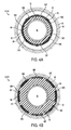
- Figures 4A and 4B show a cross-sectional view of part of the screen assembly 24 from Figures 1A (running configuration) and 1 B (operating configuration), respectively.
- Figures 4A and 4B show a base pipe 52 that defines an internal flow path 54 through which hydrocarbon fluids, for example, can flow.
- a swellable material 56 surrounds the base pipe 52.
- the swellable material 56 can be attached to the base pipe 52, such as by bonding or other suitable technique.
- Part of a rigid member 50 is shown in Figure 4A , but it is distant to the cross-section shown in Figure 4A .
- Filter mediums are shown as filter mediums 58A-H and are positioned on an exterior of the swellable material 56.
- Figure 4A shows eight filter mediums 58A-H, but screen assemblies according to various embodiments of the present invention can include any number, from one to many, of filter mediums 58A-H.
- the filter mediums 58A-H are bonded to the exterior of swellable material 56.
- a relatively low swelling or non-swelling material can be positioned between the exterior of the swellable material 56 and the filter mediums 58A-H.
- the filter mediums 58A-H can be bonded to the low swelling or non-swelling material and the low swelling or non-swelling material can be bonded to the swellable material 56.
- the low swelling or non-swelling material may assist in preventing the swellable material 56 from damaging the filter mediums 58A-H upon expansion.
- the swellable material 56 can expand upon contact with an activating fluid and displace the filter mediums 58A-H to contact a formation 66 at an internal diameter of a wellbore 68.
- the filter mediums 58A-H are filtration tubes that can filter particulate materials from hydrocarbon fluids and direct the hydrocarbon fluids to openings in the base pipe 52.
- the filter mediums 58A-H illustrated each include a housing 60 for filter material 62.
- the filter material 62 can include a filtration opening 64 through which hydrocarbon fluid can be directed to an opening in the base pipe 52.
- the housing 60 may be made of any suitable material and may be partially perforated to allow hydrocarbon fluids to enter the housing 60.
- the filter material 62 may be any suitable material, such as a fine mesh, that can filter particulate materials from hydrocarbon fluid.
- the filter mediums 58A-H have a kidney-shaped cross-sectional shape.
- the kidney-shaped cross-section may assist in attaching the filter mediums 58A-H to the swellable material 56 and may result in more surface area of the filter mediums 58A-H, as compared to filter mediums having a different cross-sectional shape, contacting the wellbore 68 upon expansion of the swellable material 56.
- Filter mediums according to other embodiments of the present invention may have any type of cross-sectional shape. Examples of these types of cross-sectional shapes include an oval, a circle, a rectangle, and a combination of two or more cross-sectional shapes.
- the filter mediums 58A-H can have a cross-sectional length that is selected based on the particular requirements of a production interval in which the screen assembly 24 is located.
- the swellable material 56 can expand upon contact with an activating fluid, as shown in Figure 4B .
- the activating fluid can include hydrocarbon fluid, water, or gas.
- Various techniques can be used to contact the swellable material 56 with an activating fluid.
- One technique includes configuring the swellable material 56 to expand upon contact with activating fluids already present within the wellbore when the screen assembly 24 is installed or with activating fluids produced by the formation 66 after installation.
- the swellable material 56 may include a mechanism for delaying swell to prevent swelling during installation. Examples of a mechanism for delaying swell include an absorption delaying layer, coating, membrane, or composition.
- Another technique includes circulating activating fluid through the well after the screen assembly 24 is installed in the well.
- swellable material 56 is capable of expansion upon its location in an environment having a temperature or a pressure that is above a pre-selected threshold in addition or alternative to an activating fluid.
- Expansion of the swellable material 56 can displace the filter mediums 58A-H to contact the formation 66 at wellbore 68.
- the thickness of the swellable material 56 can be optimized based on the diameter of the screen assembly 24 and the diameter of the wellbore 68 to maximize contact area of the filter mediums 58A-H with the wellbore 68 upon expansion.
- part of the swellable material 56 expands between the filter mediums 58A-H and contacts the formation 66 at wellbore 68 between the filter mediums 58A-H to conform to non-uniform wellbore diameters.
- the swelled screen assembly 24 can reduce or eliminate annular flow of hydrocarbon and other fluids, provide multiple flow paths for filtered hydrocarbon fluids, and provide stabilization to the wellbore 68.
- the swelled screen assembly 24 can support the formation 66 to prevent formation collapse.
- the swelled screen assembly 24 can provide an amount of collapse support within a range of 500 psi to 2000 psi (3.4 MPa to 14 MPa).
- Rigid members that support filter mediums can include pistons disposed in openings of the rigid members.
- the pistons may be telescoping pistons that can support the filter mediums in a running configuration and an operating configuration.
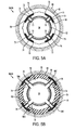
- Figures 5A and 5B show a cross-sectional view of one of the rigid members 50 of the screen assembly 24 from Figures 1A (running configuration) and 1B (operating configuration), respectively.
- the base pipe 52 includes openings 70 in a sidewall portion of the base pipe 52.
- the rigid member 50 includes openings 72 that are in fluid communication with the openings 70 of the base pipe 52.
- Pistons 74 are disposed in the openings 72 and can be coupled to filter mediums.
- FIGS 5A and 5B illustrate a rigid member 50 that can support four filter mediums that are designated 58A, 58C, 58E, and 58G.
- Rigid members according to various embodiments of the present invention, however, can support any number of filter mediums.
- the filter mediums 58A, 58C, 58E, 58G can be coupled to a low swelling or non-swelling material 76.
- the low-swelling or non-swelling material 76 may assist the rigid member 50 in supporting the filter mediums 58A, 58C, 58E, 58G by providing a temporary seal between the filter mediums 58A, 58C, 58E, 58G and rigid member 50.
- the low swelling or non-swelling material 76 is a low swelling or non-swelling rubber.
- Pistons 74 may each include a telescoping portion 78 that extends radially from the openings 72, as shown in Figure 5B , when the swellable material 56 expands to displace the filter mediums 58A, 58C, 58E, 58G to contact the wellbore 68 at the formation 66.
- grooves 80 in the rigid members 50 circumferential to the pistons 74 can receive O-rings and/or safety catch rings.
- the O-rings may provide a seal to prevent fluids from traveling between the pistons 74 and the rigid member 50.
- the safety catch rings may prevent the pistons 74 from exiting the openings 72, such as when the swellable material 56 expands.
- FIGS 5A and 5B show four filter mediums 58A, 58C, 58E, 58G coupled to four pistons 74.
- Rigid member 51 from Figures 2 and 3 can include a similar cross-sectional arrangement of the other four filter mediums 58B, 58D, 58F, 58H shown in figures 4A and 4B .
- Rigid member 51 can be located a selected longitudinal distance from the cross-section shown in figures 5A and 5B .
- Rigid member 51 may be rotated forty-five degrees relative to rigid member 50 to allow filter mediums 58A-H to be positioned adjacent to each other.
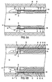
- FIGS. 6A and 6B illustrate cross-sectional side views of one embodiment of the screen assembly 24 disposed in a wellbore 68 in a running configuration and operating configuration, respectively.
- the screen assembly includes a base pipe 52 that defines an internal flow path 54 through which hydrocarbon fluids can travel.
- a rigid member 50 is disposed exterior to a first portion of the base pipe 52.
- the rigid member 50 may be a ring made from a metal, composite polymer, non-swelling rubber, or the like. Examples of metals from which the rigid member may be made include steel, iron, brass, copper, bronze, tungsten, titanium, cobalt, nickel, and a combination of these and other types of materials.
- an interface layer is disposed between the base pipe 52 and at least part of the rigid member 50.
- the interface layer may bond the rigid member 50 to the base pipe 52.
- the interface layer may also provide a seal between the rigid member 50 and the base pipe 52 to prevent annular flow of fluids from formation 66.
- the base pipe 52 includes openings 70 in a sidewall portion of the base pipe 52.
- the openings 70 are in fluid communication with filter mediums 58A, 58E through openings 72 in the rigid member 50.
- the filter mediums 58A, 58E are supported by the rigid member 50 in the running configuration.
- a piston 74 is disposed in each of the openings 72. The pistons 74 allow for fluid communication between the filter mediums 58A, 58E and base pipe openings 70.
- Swellable material 56 is disposed exterior to a second portion of the base pipe 52 and longitudinally adjacent to the rigid member 50.
- the swellable material 56 is positioned between the base pipe 52 and part of each of the filter mediums 58A, 58E.
- the swellable material 56 can retain an initial size during a running configuration and can expand upon contact with an activating fluid in an operating configuration.
- the swellable material 56 can displace the filter mediums 58A, 58E to contact the wellbore 68 when the swellable material 56 expands in the operating configuration.
- the filter mediums 58A, 58E each include a housing 60 for filter material 62.
- the housing 60 includes perforations 59 through which hydrocarbon fluids produced by the formation 66 can flow to the filter material 62.
- the filter material 62 can filter particulate materials from the hydrocarbon fluids and direct the filtered hydrocarbon fluids through a filtration opening 64 to the flow path 54 through the base pipe openings 70 and rigid member openings 72.
- the pistons 74 can support the filter mediums 58A, 58E in the running configuration and the operating configuration.
- the pistons 74 may be coupled to the filter mediums 58A, 58E and the pistons 74 can include telescoping portions 78 that can extend radially from the rigid member openings 72 when the swellable material 56 expands and displaces the filter mediums 58A, 58E.
- the rigid member 50 can isolate openings from the swellable material 56 to reduce or eliminate plugging and/or can allow the screen assembly to be constructed without requiring openings to be included in the swellable material 56.
- Screen assemblies according to certain embodiments of the present invention can be constructed using multiple rigid members supporting multiple filter mediums extending longitudinally along an exterior of a base pipe.
- Figures 7A and 7B show a cross-sectional view of part of a screen assembly 200 with multiple rigid members in a running configuration and an operating configuration, respectively.
- the screen assembly 200 includes a base pipe 202 that has openings 204 in a sidewall portion of the base pipe 202.
- the base pipe 202 can define an internal flow path 203 for hydrocarbon fluids produced by a formation 205.
- a first rigid member 206 is disposed exterior to a first circumferential portion of the base pipe 202.
- a second rigid member 208 is disposed exterior to a second circumferential portion of the base pipe 202.
- Swellable material 210 is disposed exterior to a third circumferential portion of the base pipe 202 between the first circumferential portion and the second circumferential portion.
- Second swellable material 212 may also be disposed exterior to a fourth circumferential portion of the base pipe 202 and longitudinally adjacent to the second rigid member 208.
- a filter medium 214 is disposed exterior to the swellable material 210 and of part of the first and second rigid members 206, 208.
- the filter medium 214 can be in fluid communication with the internal flow path 203 through two base pipe openings 204 and openings 216 in each of the first rigid member 206 and the second rigid member 208.
- the filter medium 214 includes a housing 218 with selected perforations 220 that allow hydrocarbon fluid to flow to a filter media 222 disposed within the housing 218.
- the filter media 222 can filter particulate materials from hydrocarbon fluid and direct the filtered hydrocarbon fluid to one or both openings 216 in the first and second rigid members 206, 208.
- a second filter medium 221 is disposed exterior to the second swellable material 212 and part of the second rigid member 208.
- the second filter medium 220 may be constructed similar to the filter medium 214 and be configured to direct filtered hydrocarbon fluid to a second opening 223 in second rigid member 208 or to an opening in another rigid member (not shown).
- Each of the openings 216 has a piston 224 disposed within it.
- Each of the pistons 224 can be coupled to the filter medium 214 and each of the pistons 224 can include a telescoping portion 226.
- the second opening 223 includes a second piston 228 that is constructed similar to pistons 224.
- the swellable material 210 and second swellable material 212 can expand radially to displace the filter medium 214 and second filter medium 220 to contact with the formation 205.
- the activating fluid include hydrocarbon fluid, water, and gas.
- the telescoping portion 226 of pistons 224 can extend radially from openings 216 to provide support to the filter medium 214 during the operating configuration and provide a conduit through which hydrocarbon fluid can flow from the filter media 222 through openings 216 to the internal flow path 203.
- the second piston 228 may perform similarly for the second filter medium 220 during the operating configuration.
- FIGS 7A and 7B illustrate rigid members located proximate to ends of filter mediums.
- rigid members are located proximate to other portions of filter mediums.
- a rigid member can support a filter medium proximate to a middle of the filter medium during a running configuration and include openings through which hydrocarbon fluid can flow from the filter medium to an internal flow path of a base pipe.
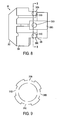
- FIG 8 is a side view of one embodiment of the rigid member 50 from Figures 6A-6B .
- the rigid member 50 is a ring that can be located exterior to a portion of a base pipe.
- the rigid member 50 includes a sloped portion 302, an intervening portion 304, and a filter medium support portion 306.
- the sloped portion 302 has a sloping shape to prevent damage to the remaining portions of the rigid member 50 during installation of the rigid member 50 in a bore.
- the intervening portion 304 may connect the sloped portion 302 and the filter medium support portion 306 and provide stability to the rigid member 50 to reduce or prevent damage to filter mediums or other components of a screen assembly when installed in the wellbore.
- the filter medium support portion 306 can provide support to filter mediums of the screen assembly.
- the filter medium support portion 306 includes receiving portions 308A-C.
- Each of the receiving portions 308-C includes a respective opening 310A-C and each of the receiving portions 308A-C can support a respective filter medium.
- each of the receiving portions 308A-C may be grooves that can receive a filter medium in a running configuration and allow the filter medium to detach from the grooves during an operating configuration.
- the openings 310A-C can provide fluid communication to an internal flow path of a base pipe and can receive a piston for supporting the filter mediums during the running configuration and an operating configuration.
- the receiving portions 308A-C can be staggered to support overlap of filter mediums and to define grooves.
- Figure 8 shows one receiving portion 308B having a different length than the other receiving portions 308A, 308C.
- Figure 9 is a cross-sectional view of rigid member 300 along line 9-9. Openings 310A-D are shown in Figure 9 as defined by grooves in filter medium support portion 306.
- a filter medium can be positioned over 310A and coupled to a piston disposed in opening 310A.
- each of openings 310B-D can be associated with a respective filter medium.
- the rigid member 50 may be made from a metal, composite polymer, non-swelling rubber, or the like.
- metals from which the rigid member 50 may be made include steel, iron, brass, copper, bronze, tungsten, titanium, cobalt, nickel, and a combination of these or other types of materials.
- Screen assemblies can include multiple rigid members.
- rigid member 50 can be located exterior to a first portion of a base pipe and a second rigid member can be located exterior to a second portion of the base pipe.
- Filter mediums can be located between the two rigid members.
- rigid member 50 can support four filter mediums and the second rigid member can support four different filter mediums.
- Figure 2 shows an example of a similar arrangement.
- the second rigid member can be rotated, for example by forty-five degrees relative to the rigid member 50, to align a receiving portion of the rigid member 50 that with a non-receiving portion of the second rigid member that has a greater cross-sectional radius.
- the filter mediums associated with the rigid member 50 and filter mediums associated with the second rigid member can be positioned adjacent to each other in an alternating arrangement.
- Swellable material can be formed from one or more materials that swell upon contact with an activating fluid.
- the swellable material may be a polymer that is capable of swelling to a size that is multiple times its initial size upon contact with an activating fluid that stimulates the material to expand.
- the swellable material swells upon contact with an activating fluid that is a hydrocarbon fluid or a gas.
- the hydrocarbon fluid is absorbed by the swellable material and the absorption causes the volume of the swellable material to increase, thereby expanding radially.
- the swellable material may expand the filter mediums and part of the outer surface of the swellable material contacts a formation face in an open hole completion or a casing wall in a cased wellbore.
- the swellable material may be made from an elastic polymer.
- elastic polymers include ethylene propylene diene monomer (EPDM) rubber, styrene butadiene, natural rubber, ethylene propylene monomer rubber, ethylene vinyl acetate rubber, hydrogenized acrylonitrile butadiene rubber, acylonitrile butadiene rubber, isoprene rubber, chloroprene rubber and polynorbornene.
- EPDM ethylene propylene diene monomer
- styrene butadiene natural rubber
- ethylene propylene monomer rubber ethylene vinyl acetate rubber
- hydrogenized acrylonitrile butadiene rubber acylonitrile butadiene rubber
- isoprene rubber chloroprene rubber and polynorbornene
- the swellable material may also include other materials dissolved in, or in mechanical mixture, with the other materials that form the swellable material. Examples of other materials include fibers of cellulose, polyviny
- the swellable material is configured to expand upon contact with an activating fluid that is water.
- the swellable material may be a water-swellable polymer such as a water-swellable elastomer or water-swellable rubber. More specifically, the swellable material may be a water-swellable hydrophobic polymer or water-swellable hydrophobic copolymer such as a water-swellable hydrophobic porous copolymer.
- Other polymers that can be used to form the swellable material include hydrophilic monomers and hydrophobically modified hydrophilic monomers.
- hydrophilic monomers examples include acrylamide, 2-acrylamido-2methyl propane sulfonic acid, N,N-dimethylacrylamide, vinyl pyrrolidone, dimethylaminoethy1 methacrylate, acrylic acid, trimethylammoniumethyl, methacrylate chloride, dimethylaminopropylmethacrylamide, methacrylamide, and hydroxyethyl acylate.
- hydrophobically modified hydrophilic monomers can be utilized in accordance with certain embodiments.
- examples of hydophobically modified hydrophilic monomers include alkyl acrylates, alkyl methacrylates, alkyl acrylamides, alkyl methacrylamides (where alkyl radicals have from about 4 to about 22 carbon atoms), alkyl dimethylammoniumethyl methacrylate chloride and alkyl dimethylammoniumethyl methacrylate iodide (where the alkyl radicals have from about 4 to about 22 carbon atoms), alkyl dimethylammonium-propylmethacrylamide bromide, alkyl dimethylammonium propylmethacrylamide chloride and alkyl dimethylammonium-propylmethacrylamide iodide (where the alkyl groups have from about 4 to about 22 carbon atoms).
- Polymers suitable in swellable material can be prepared by polymerizing any one or more of the hydrophilic monomers with any one or more of the hydrophobically modified hydrophilic monomers.
- the polymerization reaction can be formed in various ways, an example of which is described in U.S. Patent No. 6,476,169 , which is incorporated herein by reference.
- These polymers may have estimated molecular weights in the range from about 100,000 to about 10,000,000, with a preferred range of 250,000 to about 3,000,000.
- These polymers may also have mole ratios of the hydrophilic monomer(s) to the hydrophobically modified hydrophilic monomer(s) in the range of from about 99.98:0.02 to about 90:10.
- the swellable material may be made from a salt polymer such as polyacrylamide or modified crosslinked poly(meth)acrylate that tends to attract water from salt water through osmosis.
- a salt polymer such as polyacrylamide or modified crosslinked poly(meth)acrylate that tends to attract water from salt water through osmosis.
- the salt polymer allows water molecules to pass, but prevents passage of dissolved salts.
Landscapes
- Life Sciences & Earth Sciences (AREA)
- Engineering & Computer Science (AREA)
- Geology (AREA)
- Mining & Mineral Resources (AREA)
- Physics & Mathematics (AREA)
- Environmental & Geological Engineering (AREA)
- Fluid Mechanics (AREA)
- General Life Sciences & Earth Sciences (AREA)
- Geochemistry & Mineralogy (AREA)
- Filtering Materials (AREA)
- Filtration Of Liquid (AREA)
- Lubrication Details And Ventilation Of Internal Combustion Engines (AREA)
Applications Claiming Priority (1)
| Application Number | Priority Date | Filing Date | Title |
|---|---|---|---|
| US12/539,749 US8256510B2 (en) | 2009-08-12 | 2009-08-12 | Control screen assembly |
Publications (2)
| Publication Number | Publication Date |
|---|---|
| EP2295717A2 true EP2295717A2 (de) | 2011-03-16 |
| EP2295717A3 EP2295717A3 (de) | 2011-09-14 |
Family
ID=42782187
Family Applications (1)
| Application Number | Title | Priority Date | Filing Date |
|---|---|---|---|
| EP10172541A Withdrawn EP2295717A3 (de) | 2009-08-12 | 2010-08-11 | Bohrlochfilteranordnung |
Country Status (7)
| Country | Link |
|---|---|
| US (2) | US8256510B2 (de) |
| EP (1) | EP2295717A3 (de) |
| CN (1) | CN101994498B (de) |
| AU (1) | AU2010206105B2 (de) |
| BR (1) | BRPI1004054A2 (de) |
| MY (1) | MY165970A (de) |
| SG (1) | SG169288A1 (de) |
Cited By (1)
| Publication number | Priority date | Publication date | Assignee | Title |
|---|---|---|---|---|
| EP2844829A4 (de) * | 2012-06-28 | 2016-07-27 | Halliburton Energy Services Inc | Schwellbare siebanordnung mit einwärtsflusssteuerung |
Families Citing this family (29)
| Publication number | Priority date | Publication date | Assignee | Title |
|---|---|---|---|---|
| US8256510B2 (en) * | 2009-08-12 | 2012-09-04 | Halliburton Energy Services, Inc. | Control screen assembly |
| US8281854B2 (en) * | 2010-01-19 | 2012-10-09 | Baker Hughes Incorporated | Connector for mounting screen to base pipe without welding or swaging |
| GB201019358D0 (en) * | 2010-11-16 | 2010-12-29 | Darcy Technologies Ltd | Downhole method and apparatus |
| CN102182430A (zh) * | 2011-03-28 | 2011-09-14 | 刘春博 | 水平井可钻式石英砂滤管防砂配套管柱 |
| EP2766564A4 (de) | 2011-10-14 | 2015-11-25 | Halliburton Energy Services Inc | Bohrlochsieb mit verstärkungsfilter |
| CA2864052A1 (en) | 2012-02-02 | 2013-08-08 | A. O. Smith Corporation | Systems, compositions and methods for providing safe and healthy water and water-based products |
| US9038741B2 (en) | 2012-04-10 | 2015-05-26 | Halliburton Energy Services, Inc. | Adjustable flow control device |
| CN104246118A (zh) | 2012-04-18 | 2014-12-24 | 哈利伯顿能源服务公司 | 流动控制装置的设备、系统和方法 |
| US9273537B2 (en) * | 2012-07-16 | 2016-03-01 | Schlumberger Technology Corporation | System and method for sand and inflow control |
| US9151143B2 (en) | 2012-07-19 | 2015-10-06 | Halliburton Energy Services, Inc. | Sacrificial plug for use with a well screen assembly |
| US20140027108A1 (en) * | 2012-07-27 | 2014-01-30 | Halliburton Energy Services, Inc. | Expandable Screen Using Magnetic Shape Memory Alloy Material |
| WO2014113029A1 (en) * | 2013-01-20 | 2014-07-24 | Halliburton Energy Services, Inc. | Expandable well screens with slurry delivery shunt conduits |
| RU2635315C2 (ru) * | 2013-02-27 | 2017-11-10 | Хэллибертон Энерджи Сервисиз, Инк. | Отклонитель фрезы, содержащий расширяющийся материал для предотвращения протекания текучей среды через материал |
| AU2013385681B2 (en) * | 2013-04-01 | 2017-02-23 | Halliburton Energy Services, Inc. | Well screen assembly with extending screen |
| US9416633B2 (en) * | 2013-04-30 | 2016-08-16 | Baker Hughes Incorporated | Screen assembly |
| US20140360613A1 (en) * | 2013-06-07 | 2014-12-11 | Baker Hughes Incorporated | Instrumentation line protection and securement system |
| US9970269B2 (en) * | 2013-06-28 | 2018-05-15 | Halliburton Energy Services, Inc. | Expandable well screen having enhanced drainage characteristics when expanded |
| GB2532358B (en) * | 2013-06-28 | 2020-01-22 | Halliburton Energy Services Inc | Expandable well screen having enhanced drainage characteristics when expanded |
| CA2918791A1 (en) | 2013-07-25 | 2015-01-29 | Schlumberger Canada Limited | Sand control system and methodology |
| US9777548B2 (en) * | 2013-12-23 | 2017-10-03 | Baker Hughes Incorporated | Conformable devices using shape memory alloys for downhole applications |
| RU2557273C1 (ru) * | 2014-06-11 | 2015-07-20 | Акционерное общество "Новомет-Пермь" (АО "Новомет-Пермь") | Скважинный расширяющийся фильтр |
| US10450843B2 (en) | 2016-06-06 | 2019-10-22 | Baker Hughes, A Ge Company, Llc | Screen assembly for a resource exploration system |
| US12110774B2 (en) * | 2017-08-24 | 2024-10-08 | Clifford Wayne Hunter | Artificial porosity-pressure adjustable formation fluid-gas control system and method |
| GB2605554B (en) * | 2017-09-15 | 2023-01-11 | Halliburton Energy Services Inc | Sand screen system with adhesive bonding |
| US11028674B2 (en) | 2018-07-31 | 2021-06-08 | Baker Hughes, A Ge Company, Llc | Monitoring expandable screen deployment in highly deviated wells in open hole environment |
| US11359484B2 (en) * | 2018-11-20 | 2022-06-14 | Baker Hughes, A Ge Company, Llc | Expandable filtration media and gravel pack analysis using low frequency acoustic waves |
| WO2020172092A1 (en) | 2019-02-20 | 2020-08-27 | Schlumberger Technology Corporation | Non-metallic compliant sand control screen |
| WO2022081440A1 (en) | 2020-10-13 | 2022-04-21 | Schlumberger Technology Corporation | Elastomer alloy for intelligent sand management |
| CN116575887B (zh) * | 2023-06-30 | 2023-11-07 | 大庆长垣能源科技有限公司 | 一种用于储气库气井的冲缝筛管 |
Citations (1)
| Publication number | Priority date | Publication date | Assignee | Title |
|---|---|---|---|---|
| US6476169B1 (en) | 2000-09-28 | 2002-11-05 | Halliburton Energy Services, Inc. | Methods of reducing subterranean formation water permeability |
Family Cites Families (27)
| Publication number | Priority date | Publication date | Assignee | Title |
|---|---|---|---|---|
| US2589506A (en) * | 1947-04-15 | 1952-03-18 | Halliburton Oil Well Cementing | Drillable packer |
| WO1996026350A1 (en) | 1995-02-14 | 1996-08-29 | Baker Hughes Incorporated | Casing with a laterally extendable tubular member and method for sand control in wells |
| EP0781893B8 (de) * | 1995-12-26 | 2007-02-14 | HALLIBURTON ENERGY SERVICES, Inc. | Vorrichtung und Verfahren zur Frühbewertung und Unterhalt einer Bohrung |
| US6173788B1 (en) | 1998-04-07 | 2001-01-16 | Baker Hughes Incorporated | Wellpacker and a method of running an I-wire or control line past a packer |
| US6341654B1 (en) * | 1999-04-15 | 2002-01-29 | Weatherford/Lamb, Inc. | Inflatable packer setting tool assembly |
| NO316428B1 (no) | 2000-04-13 | 2004-01-26 | Kvaerner Oilfield Prod As | Fremgangsmåte ved separasjon, utlöpsarrangement for en separator og fremgangsmåte for å orientere utlöpsarrangementet |
| NO312478B1 (no) | 2000-09-08 | 2002-05-13 | Freyer Rune | Fremgangsmåte for å tette ringrom ved oljeproduksjon |
| US6543545B1 (en) | 2000-10-27 | 2003-04-08 | Halliburton Energy Services, Inc. | Expandable sand control device and specialized completion system and method |
| US6571871B2 (en) | 2001-06-20 | 2003-06-03 | Weatherford/Lamb, Inc. | Expandable sand screen and method for installing same in a wellbore |
| US6719064B2 (en) | 2001-11-13 | 2004-04-13 | Schlumberger Technology Corporation | Expandable completion system and method |
| US7284603B2 (en) | 2001-11-13 | 2007-10-23 | Schlumberger Technology Corporation | Expandable completion system and method |
| US7644773B2 (en) | 2002-08-23 | 2010-01-12 | Baker Hughes Incorporated | Self-conforming screen |
| US20050252651A1 (en) * | 2002-09-06 | 2005-11-17 | Shell Oil Company | Wellbore device for selective transfer of fluid |
| OA13222A (en) | 2003-07-29 | 2006-12-13 | Shell Int Research | System for sealing a space in a wellbore. |
| WO2006003112A1 (en) | 2004-06-25 | 2006-01-12 | Shell Internationale Research Maatschappij B.V. | Screen for controlling sand production in a wellbore |
| EP1792049B8 (de) | 2004-06-25 | 2009-08-19 | Shell Internationale Research Maatschappij B.V. | Filter zur zuflussregelung von feststoffteilen in einem bohrloch |
| CA2530969C (en) | 2004-12-21 | 2010-05-18 | Schlumberger Canada Limited | Water shut off method and apparatus |
| US7984760B2 (en) | 2006-04-03 | 2011-07-26 | Exxonmobil Upstream Research Company | Wellbore method and apparatus for sand and inflow control during well operations |
| CN201013330Y (zh) * | 2007-03-14 | 2008-01-30 | 诺斯石油工具(天津)有限公司 | 复合筛管 |
| GB2448298B (en) | 2007-04-10 | 2009-12-23 | Swelltec Ltd | Downhole apparatus and method |
| GB0712345D0 (en) | 2007-06-26 | 2007-08-01 | Metcalfe Paul D | Downhole apparatus |
| US7712529B2 (en) | 2008-01-08 | 2010-05-11 | Halliburton Energy Services, Inc. | Sand control screen assembly and method for use of same |
| US7866383B2 (en) | 2008-08-29 | 2011-01-11 | Halliburton Energy Services, Inc. | Sand control screen assembly and method for use of same |
| US7814973B2 (en) | 2008-08-29 | 2010-10-19 | Halliburton Energy Services, Inc. | Sand control screen assembly and method for use of same |
| US7841409B2 (en) | 2008-08-29 | 2010-11-30 | Halliburton Energy Services, Inc. | Sand control screen assembly and method for use of same |
| US8256510B2 (en) | 2009-08-12 | 2012-09-04 | Halliburton Energy Services, Inc. | Control screen assembly |
| US8302680B2 (en) | 2009-08-12 | 2012-11-06 | Halliburton Energy Services, Inc. | Swellable screen assembly |
-
2009
- 2009-08-12 US US12/539,749 patent/US8256510B2/en not_active Expired - Fee Related
-
2010
- 2010-08-03 AU AU2010206105A patent/AU2010206105B2/en not_active Ceased
- 2010-08-11 MY MYPI2010003786A patent/MY165970A/en unknown
- 2010-08-11 BR BRPI1004054-4A patent/BRPI1004054A2/pt not_active IP Right Cessation
- 2010-08-11 SG SG201005851-9A patent/SG169288A1/en unknown
- 2010-08-11 EP EP10172541A patent/EP2295717A3/de not_active Withdrawn
- 2010-08-12 CN CN201010253332.2A patent/CN101994498B/zh not_active Expired - Fee Related
-
2012
- 2012-08-01 US US13/564,264 patent/US8579025B2/en not_active Expired - Fee Related
Patent Citations (1)
| Publication number | Priority date | Publication date | Assignee | Title |
|---|---|---|---|---|
| US6476169B1 (en) | 2000-09-28 | 2002-11-05 | Halliburton Energy Services, Inc. | Methods of reducing subterranean formation water permeability |
Cited By (1)
| Publication number | Priority date | Publication date | Assignee | Title |
|---|---|---|---|---|
| EP2844829A4 (de) * | 2012-06-28 | 2016-07-27 | Halliburton Energy Services Inc | Schwellbare siebanordnung mit einwärtsflusssteuerung |
Also Published As
| Publication number | Publication date |
|---|---|
| AU2010206105A1 (en) | 2011-03-03 |
| US8256510B2 (en) | 2012-09-04 |
| US8579025B2 (en) | 2013-11-12 |
| SG169288A1 (en) | 2011-03-30 |
| MY165970A (en) | 2018-05-18 |
| CN101994498B (zh) | 2015-11-25 |
| EP2295717A3 (de) | 2011-09-14 |
| BRPI1004054A2 (pt) | 2012-05-15 |
| US20120298352A1 (en) | 2012-11-29 |
| CN101994498A (zh) | 2011-03-30 |
| AU2010206105B2 (en) | 2016-07-14 |
| US20110036565A1 (en) | 2011-02-17 |
Similar Documents
| Publication | Publication Date | Title |
|---|---|---|
| US8579025B2 (en) | Control screen assembly | |
| US8302680B2 (en) | Swellable screen assembly | |
| AU2012383552B2 (en) | Swellable screen assembly with inflow control | |
| US7866383B2 (en) | Sand control screen assembly and method for use of same | |
| AU2009285794B2 (en) | Sand control screen assembly and method for use of same | |
| EP2329103B1 (de) | Sandkontrollsiebanordnung und verfahren dafür |
Legal Events
| Date | Code | Title | Description |
|---|---|---|---|
| PUAI | Public reference made under article 153(3) epc to a published international application that has entered the european phase |
Free format text: ORIGINAL CODE: 0009012 |
|
| AK | Designated contracting states |
Kind code of ref document: A2 Designated state(s): AL AT BE BG CH CY CZ DE DK EE ES FI FR GB GR HR HU IE IS IT LI LT LU LV MC MK MT NL NO PL PT RO SE SI SK SM TR |
|
| AX | Request for extension of the european patent |
Extension state: BA ME RS |
|
| PUAL | Search report despatched |
Free format text: ORIGINAL CODE: 0009013 |
|
| AK | Designated contracting states |
Kind code of ref document: A3 Designated state(s): AL AT BE BG CH CY CZ DE DK EE ES FI FR GB GR HR HU IE IS IT LI LT LU LV MC MK MT NL NO PL PT RO SE SI SK SM TR |
|
| AX | Request for extension of the european patent |
Extension state: BA ME RS |
|
| RIC1 | Information provided on ipc code assigned before grant |
Ipc: E21B 43/08 20060101AFI20110805BHEP Ipc: E21B 43/10 20060101ALI20110805BHEP |
|
| 17P | Request for examination filed |
Effective date: 20120314 |
|
| 17Q | First examination report despatched |
Effective date: 20170306 |
|
| STAA | Information on the status of an ep patent application or granted ep patent |
Free format text: STATUS: THE APPLICATION IS DEEMED TO BE WITHDRAWN |
|
| 18D | Application deemed to be withdrawn |
Effective date: 20170718 |