EP2295767B1 - Dispositif de dosage de carburant pour des applications aéronautiques - Google Patents
Dispositif de dosage de carburant pour des applications aéronautiques Download PDFInfo
- Publication number
- EP2295767B1 EP2295767B1 EP20100251310 EP10251310A EP2295767B1 EP 2295767 B1 EP2295767 B1 EP 2295767B1 EP 20100251310 EP20100251310 EP 20100251310 EP 10251310 A EP10251310 A EP 10251310A EP 2295767 B1 EP2295767 B1 EP 2295767B1
- Authority
- EP
- European Patent Office
- Prior art keywords
- fuel
- valve
- pressure
- push
- chamber
- Prior art date
- Legal status (The legal status is an assumption and is not a legal conclusion. Google has not performed a legal analysis and makes no representation as to the accuracy of the status listed.)
- Active
Links
Images

Classifications
-
- F—MECHANICAL ENGINEERING; LIGHTING; HEATING; WEAPONS; BLASTING
- F02—COMBUSTION ENGINES; HOT-GAS OR COMBUSTION-PRODUCT ENGINE PLANTS
- F02C—GAS-TURBINE PLANTS; AIR INTAKES FOR JET-PROPULSION PLANTS; CONTROLLING FUEL SUPPLY IN AIR-BREATHING JET-PROPULSION PLANTS
- F02C9/00—Controlling gas-turbine plants; Controlling fuel supply in air- breathing jet-propulsion plants
- F02C9/26—Control of fuel supply
- F02C9/263—Control of fuel supply by means of fuel metering valves
-
- F—MECHANICAL ENGINEERING; LIGHTING; HEATING; WEAPONS; BLASTING
- F02—COMBUSTION ENGINES; HOT-GAS OR COMBUSTION-PRODUCT ENGINE PLANTS
- F02C—GAS-TURBINE PLANTS; AIR INTAKES FOR JET-PROPULSION PLANTS; CONTROLLING FUEL SUPPLY IN AIR-BREATHING JET-PROPULSION PLANTS
- F02C7/00—Features, components parts, details or accessories, not provided for in, or of interest apart form groups F02C1/00 - F02C6/00; Air intakes for jet-propulsion plants
- F02C7/22—Fuel supply systems
- F02C7/232—Fuel valves; Draining valves or systems
-
- F—MECHANICAL ENGINEERING; LIGHTING; HEATING; WEAPONS; BLASTING
- F02—COMBUSTION ENGINES; HOT-GAS OR COMBUSTION-PRODUCT ENGINE PLANTS
- F02C—GAS-TURBINE PLANTS; AIR INTAKES FOR JET-PROPULSION PLANTS; CONTROLLING FUEL SUPPLY IN AIR-BREATHING JET-PROPULSION PLANTS
- F02C9/00—Controlling gas-turbine plants; Controlling fuel supply in air- breathing jet-propulsion plants
- F02C9/26—Control of fuel supply
- F02C9/28—Regulating systems responsive to plant or ambient parameters, e.g. temperature, pressure, rotor speed
-
- Y—GENERAL TAGGING OF NEW TECHNOLOGICAL DEVELOPMENTS; GENERAL TAGGING OF CROSS-SECTIONAL TECHNOLOGIES SPANNING OVER SEVERAL SECTIONS OF THE IPC; TECHNICAL SUBJECTS COVERED BY FORMER USPC CROSS-REFERENCE ART COLLECTIONS [XRACs] AND DIGESTS
- Y10—TECHNICAL SUBJECTS COVERED BY FORMER USPC
- Y10T—TECHNICAL SUBJECTS COVERED BY FORMER US CLASSIFICATION
- Y10T137/00—Fluid handling
- Y10T137/7722—Line condition change responsive valves
- Y10T137/7758—Pilot or servo controlled
- Y10T137/7762—Fluid pressure type
- Y10T137/7764—Choked or throttled pressure type
- Y10T137/7768—Pilot controls supply to pressure chamber
-
- Y—GENERAL TAGGING OF NEW TECHNOLOGICAL DEVELOPMENTS; GENERAL TAGGING OF CROSS-SECTIONAL TECHNOLOGIES SPANNING OVER SEVERAL SECTIONS OF THE IPC; TECHNICAL SUBJECTS COVERED BY FORMER USPC CROSS-REFERENCE ART COLLECTIONS [XRACs] AND DIGESTS
- Y10—TECHNICAL SUBJECTS COVERED BY FORMER USPC
- Y10T—TECHNICAL SUBJECTS COVERED BY FORMER US CLASSIFICATION
- Y10T137/00—Fluid handling
- Y10T137/7722—Line condition change responsive valves
- Y10T137/7758—Pilot or servo controlled
- Y10T137/7762—Fluid pressure type
- Y10T137/7769—Single acting fluid servo
- Y10T137/777—Spring biased
-
- Y—GENERAL TAGGING OF NEW TECHNOLOGICAL DEVELOPMENTS; GENERAL TAGGING OF CROSS-SECTIONAL TECHNOLOGIES SPANNING OVER SEVERAL SECTIONS OF THE IPC; TECHNICAL SUBJECTS COVERED BY FORMER USPC CROSS-REFERENCE ART COLLECTIONS [XRACs] AND DIGESTS
- Y10—TECHNICAL SUBJECTS COVERED BY FORMER USPC
- Y10T—TECHNICAL SUBJECTS COVERED BY FORMER US CLASSIFICATION
- Y10T137/00—Fluid handling
- Y10T137/7722—Line condition change responsive valves
- Y10T137/7781—With separate connected fluid reactor surface
- Y10T137/7782—With manual or external control for line valve
-
- Y—GENERAL TAGGING OF NEW TECHNOLOGICAL DEVELOPMENTS; GENERAL TAGGING OF CROSS-SECTIONAL TECHNOLOGIES SPANNING OVER SEVERAL SECTIONS OF THE IPC; TECHNICAL SUBJECTS COVERED BY FORMER USPC CROSS-REFERENCE ART COLLECTIONS [XRACs] AND DIGESTS
- Y10—TECHNICAL SUBJECTS COVERED BY FORMER USPC
- Y10T—TECHNICAL SUBJECTS COVERED BY FORMER US CLASSIFICATION
- Y10T137/00—Fluid handling
- Y10T137/7722—Line condition change responsive valves
- Y10T137/7837—Direct response valves [i.e., check valve type]
-
- Y—GENERAL TAGGING OF NEW TECHNOLOGICAL DEVELOPMENTS; GENERAL TAGGING OF CROSS-SECTIONAL TECHNOLOGIES SPANNING OVER SEVERAL SECTIONS OF THE IPC; TECHNICAL SUBJECTS COVERED BY FORMER USPC CROSS-REFERENCE ART COLLECTIONS [XRACs] AND DIGESTS
- Y10—TECHNICAL SUBJECTS COVERED BY FORMER USPC
- Y10T—TECHNICAL SUBJECTS COVERED BY FORMER US CLASSIFICATION
- Y10T137/00—Fluid handling
- Y10T137/8593—Systems
- Y10T137/85978—With pump
- Y10T137/85986—Pumped fluid control
- Y10T137/86002—Fluid pressure responsive
- Y10T137/8601—And pilot valve
Definitions
- This invention relates to a fuel system and in particular to a fuel system suitable for use in aerospace applications.
- a typical fuel system for use in such applications includes a pumping arrangement from which fuel is supplied at high pressure to a fuel metering unit (FMU).
- the FMU includes a metering valve operable to control the rate of fuel supply to an engine burner manifold.
- a pressure drop control valve (PDCV) monitors the drop in fuel pressure across the metering valve and controls the operation of a spill valve to maintain the pressure drop at a substantially fixed level.
- a pressure raising valve is provided between the metering valve and the burner manifold, and operates to assist in maintaining the fuel pressure within the fuel system at a level above a predetermined minimum level, typically of the order of 200 to 300 psid above the minimum level, to ensure the correct operation of fuel-draulic devices, for example variable inlet guide vane actuators, which receive fuel from the FMU.
- the pumping arrangement is typically driven, via a gear box, by the engine. Consequently, the rate at which fuel is supplied by the pumping arrangement to the FMU is dependent upon engine speed. Although at normal engine operating speeds the pumping arrangement is able to supply sufficient fuel to the FMU, when the engine is turning only at low speed, for example under windmill relight conditions where the engine speed may be as low as 5% of its normal maximum operating speed, parasitic leakage losses within the pumping arrangement and the FMU may be significantly large that the pumping arrangement is unable to deliver the fuel flow required to start the engine.
- a number of techniques are known for use in ensuring that the pumping arrangement can deliver sufficient fuel flow to the engine burner manifold in such circumstances.
- these techniques involve reducing the system pressure rise at start in order to reduce the parasitic losses within the pumping arrangement and the FMU, thereby ensuring that there is adequate fuel flow available to start the engine.
- US 6666014 , US 6176076 and US 6321527 all describe arrangements whereby the pressure applied to the control chamber of the PRV, urging the PRV towards a closed position can be switched between a normal operating level whereby the PRV operates to ensure that the system pressure is held at or above a predetermined level sufficient to ensure correct operation of fuel-draulic devices, and a reduced level at which the PRV opens at reduced system pressures to ensure that parasitic leakages are reduced sufficiently to allow the pump to deliver the required fuel flow to the engine.
- a normal operating level whereby the PRV operates to ensure that the system pressure is held at or above a predetermined level sufficient to ensure correct operation of fuel-draulic devices
- a reduced level at which the PRV opens at reduced system pressures to ensure that parasitic leakages are reduced sufficiently to allow the pump to deliver the required fuel flow to the engine It will be appreciated that although such arrangements ensure that the required fuel flow is delivered to the engine under windmill relight conditions, they are relatively complex, and could adversely affect the operation of the PRV under
- US 7234293 describes an arrangement in which the PRV incorporates a push piston, movement of the push piston assisting in moving the PRV to its open position.
- the push piston is supplied with fuel under pressure from the larger gear pump of a twin gear pump arrangement. When operating under low speed conditions, both pumps will be loaded, thus high pressure fuel is applied to the push piston to open the PRV. At higher operating speeds, the larger pump is normally unloaded thus the pressure applied to the push piston is reduced.
- Such an arrangement is only suitable for use with twin gear pump systems. Further, under other operating conditions the dynamic performance of the system may be adversely affected.
- GB 2305975 describes a fuel system including a pressure raising valve including a delivery chamber and a control chamber, the fuel pressure within the control chamber applying a load urging the valve member of the pressure raising valve towards a closed position, wherein the control chamber pressure is controllable by a valve.
- a fuel metering unit comprising a metering valve operable to control the supply of fuel to a delivery chamber of a pressure raising valve (PRV), the PRV including a valve member movable under the influence of the pressure within the delivery chamber between a closed position and an open position in which fuel is able to flow from the delivery chamber to an outlet port, and characterised by a push-piston movable under the influence of the pressure within a control chamber to urge the valve member towards its open position, wherein the control chamber communicates with a valve control port provided on the metering valve such that the pressure within the control chamber is dependent upon whether the valve control port is open or closed.
- PRV pressure raising valve
- valve control port may depend upon, for example, the nature of the FMU.
- valve control port is arranged to be open when the metering valve occupies an engine start zero fuel flow delivery position.
- the FMU can be used with a range of designs of pumping arrangement. For example it can be used with single and twin gear pump arrangements or with single or twin vane pump arrangements, or combinations thereof. As the metering valve or spill valve is used to control the pressure applied to the control chamber, it will be appreciated that the addition of extra components Is avoided, thus the FMU is relatively simple.
- a restricted flow passage provides a restricted flow path between the control chamber and the delivery chamber, thus permitting return movement of the push piston when the valve control port is closed.
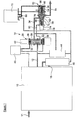
- the fuel system illustrated in Figure 1 comprises a pumping unit 10 arranged to supply fuel from a tank line 11 to a supply line 12 of a fuel metering unit (FMU) 14 under high pressure.
- the precise nature of the pumping unit 10 is not of relevance to the invention, and may be selected from a range of suitable pumping units that are well known to those skilled in the art, and will not be described in detail, other than to note that it comprises an arrangement of low pressure and high pressure pumping elements, along with any necessary switching and relief valve elements.
- the metering valve 28 comprises a valve member 30 movable within a bore formed in a housing 32, the position of the valve member 30 within the housing 32 controlling the supply of fuel from the supply line 12 through the metering valve 28 to a delivery line 34.
- the position occupied by the valve member 30 is controlled by controlling the fuel pressures applied to chambers 36, 38 located at each end of the valve member 30.
- a servo valve 40 is used to control these pressures and thereby controls the position occupied by the valve member 30.
- An LVDT or other position sensor 42 monitors the position occupied by the valve member 30 and provides this information to a control unit (not shown) which controls the operation of the servo valve 40. It will thus be appreciated that the metering valve 28 can be controlled in a closed loop manner.
- a pressure drop control valve (PDCV) 44 is connected between the supply line 12 and delivery line 34 and is operable to control the operation of a spill valve 46.
- the PDCV 44 controls the operation of the spill valve 46 in such a manner as to maintain a substantially uniform pressure drop across the metering valve 28.
- the pressure drop is typically within the range 75 to 125 psid. If the pressure drop across the metering valve 28 increases above a desired maximum level, then the PDCV 44 causes the spill valve 46 to move to a position in which there is an increase in the volume of fuel flowing through the spill valve 46 from the supply line 12 to a low pressure line 18.
- the delivery line 34 is connected to a pressure raising valve in the form of a pressure raising and shut-off valve (PRSOV) 52 which serves, in use, to assist in maintaining the fuel pressure within the FMU 14 at above a predetermined minimum pressure, and is also used in controlling the termination of fuel supply to the burner manifold of the associated engine when the engine is to be shut down.
- PRSOV 52 comprises a valve member 54 slidable within a housing 56, and defining with the housing 56 a delivery chamber 58 and a second chamber 60.
- the delivery line 34 communicates with the delivery chamber 58, and the position occupied by the valve member 54 determines whether or not an outlet port 62 also communicates with the delivery chamber 58, and thus controls the delivery of fuel along a line 64 to the burner manifold.
- valve member 54 is urged towards a closed position in which the outlet port 62 is closed by means of a spring 66 and by means of the fuel pressure within the second chamber 60 which is set by a fuel pressure potentiometer network 68, in normal use, and which can be set to a high pressure by a shut-off servo valve 70 when engine shut down is desired.
- the PRSOV 52 further includes, at an opposite end of the housing 56 to the valve member 54, an equal area push-piston 72 movable under the influence of the fuel pressure within a control chamber 74 defined between the push-piston 72 and the housing 56, the push-piston 72 being arranged such that when the valve member 54 occupies its closed position, movement of the push-piston 72 from its left hand most position towards the right hand most position, as viewed in Figure 1 , results in the push-piston 72 urging the valve member 54 towards its open position, the movement of the push-piston 72 being transmitted to the valve member 54 by means of a push-rod 76 extending across the delivery chamber 58.
- the push-rod 76 can form part of the structure of either the valve member 54 or the push-piston 72. In the embodiment described herein it preferably forms part of the structure of the valve member 54.
- a position sensor 78 monitors the position of the push-piston 72. Conveniently, the position sensor 78 comprises an inductive probe, but it will be appreciated that this need not always be the case.
- the control chamber 74 is connected via a control line 80 to a valve control port 82 provided on a valve of the FMU, in this case the metering valve 28, with the result that the fuel pressure applied to the control chamber 74 is controlled by the operation of the metering valve 28.
- the push-piston 72 is provided with a restricted flow passage 84 defining a restricted flow path between the control chamber 74 and the delivery chamber 58.
- the metering valve 28 operates to control the rate at which fuel is delivered to the engine manifold by controlling the rate at which fuel flows from the supply line 12 to the delivery line 34, the PDCV 44 and spill valve 46 ensuring that a substantially uniform pressure drop is maintained across the metering valve 28.
- the fuel pressure within the delivery chamber 58 of the PRSOV 52 is sufficient to ensure that the valve member 54 occupies its open position, the fuel pressure within the delivery chamber 58 being sufficient to hold the valve member 54 against the action of the spring 66 and fuel pressure within the second chamber 60. Fuel is thus able to flow from the delivery chamber 58 through the outlet port 62 and along the line 64 to the burner manifold.
- the spring 66 and fuel pressure within the second chamber 60 serve to control the operation of the PRSOV 52 to ensure that the required minimum system pressure is maintained.
- valve member 30 obscures the control port 82, and so high pressure fuel is not supplied directly from the supply line 12 to the control chamber 74 via control port 82 and line 80, and the push-piston 72 is inactive.
- the metering valve 28 Prior to engine start-up the metering valve 28 will occupy a closed or zero fuel flow position in which no fuel is delivered from the supply line 12 to the delivery line 34. The fuel pressure within the delivery chamber 58 will thus be low, and the valve member 54 will occupy its closed position, the spring 66 holding the valve member 54 in this position. With the metering valve 28 in this position, the control port 82 is open, and thus the control chamber 74 will be at substantially the same pressure as the supply line 12.
- the pressure within the control chamber 74 also increases by virtue of the fact that the control port 82 is open.
- the control port 82 remains open.
- the fuel pressure in the control chamber 74 which is substantially the same as that in the supply line 12, is greater than the fuel pressure in the delivery chamber 58, by virtue of the pressure drop across the metering valve 28.
- the push-piston 72 is able to move under the action of the pressure within the control chamber 74 to the right in the orientation illustrated.
- the movement of the push-piston 72 results in co-operation between the push-piston 72 and the push-rod 76, and thus the movement of the push-piston 72 will also result in further opening movement of the valve member 54 against the action of the spring 66 and fuel pressure within the second chamber 60.
- the metering valve 28 is controlled in such a manner as to increase the rate of fuel supply to the delivery line 34, thus increasing the rate of fuel supply to the engine burners.
- Such operation of the metering valve 28 will result in the control port 82 being closed by virtue of the valve member 30 of the metering valve 28 further moving in an upwards direction as illustrated in Figure 1 , thus breaking the direct connection between the fuel pressure within the control chamber 74 and the fuel pressure within the supply line 12. With the connection between the control chamber 74 and the supply line 12 broken, the fuel pressure within the control chamber 74 becomes substantially equal to the fuel pressure in the delivery chamber 58 by virtue of the restricted passage 84 in the push-piston 72.
- the push-piston 72 remains in a static equalised right-most position, as illustrated in Figure 1 , no longer acting on the PRSOV push-rod 76.
- the fuel pressure within the supply line 12 will increase resulting, in turn, in an increase in the fuel pressure within the delivery chamber 58, which acts independently of the push-piston 72 on the PRSOV valve member 54 urging it towards its fully open position.
- the PRSOV 52 operates as normal to maintain a minimum fuel pressure within the system that is sufficient to ensure correct operation of the fuel-draulic devices at all engine operating conditions apart from start-up (ie engine idle). Also, operation of the PRSOV 52 to permit subsequent engine shut-down, when so desired, is re-established.
- the shut-off servo valve 70 is operated to raise the pressure within the second chamber 60 to a level sufficient to force the valve member 54 to its fully closed position, thereby terminating fuel flow to the burner manifold.
- the movement of the valve member 54 is transmitted to the push-piston 72 by the push rod 76, thereby forcing the push-piston 72 to return to its left-most position.
- the restricted passage 84 in the push-piston 72 ensures that when, at shut-down, the position of the metering valve 28 is such that the control port 82 is closed, trapped fuel in the control chamber 74 is allowed to escape to the delivery chamber 58 as the push-piston 72 is forced to the left-most position by the PRSOV valve member 54 via the push-rod 76.
- the arrangement of the invention has a number of advantages.
- the use of the metering valve to control the operation of the push-piston means that the push-piston only acts on the PRSOV valve member during start-up, and not idle or cruise, conditions.
- the reduction in system pressure thus only occurs during start-up, when there is no requirement to operate fuel-draulic devices.
- the system can also be used with a wide range of pumping units, for example single and twin gear pump arrangements, single and twin vane pump arrangements, and combinations thereof.
- the dynamic stability problems of prior arrangements where the push-piston is controlled using the output of one of a pair of gear pumps are overcome, and issues arising from movement of the push-piston during, for example, idle descent conditions are negated.
- the PDCV 44 is used instead of the metering valve 28 to control the operation of the push-piston 72.
- the valve control port 83 is provided on the PDCV 44 and is connected to the control chamber 74 by a control line 81 with the result that the fuel pressure applied to the control chamber 74, and hence the operation of the push-piston 72, is controlled by the operation of the PDCV 44.
- the design of the PDCV 44 is such that the PDCV 44 can be moved to a position in which the fuel pressure applied to the control line 81, and hence that applied to the control chamber 74, is substantially equal to that within the supply line 12 to achieve the benefits described hereinbefore.
- VDVP variable displacement vane pump
- PDCV 44 is used to control the operation of the VDVP.
- the invention is not restricted to use in such an arrangement.
Landscapes
- Engineering & Computer Science (AREA)
- Chemical & Material Sciences (AREA)
- Combustion & Propulsion (AREA)
- Mechanical Engineering (AREA)
- General Engineering & Computer Science (AREA)
- Fuel-Injection Apparatus (AREA)
Claims (6)
- Unité de dosage de carburant (FMU) comprenant une vanne de dosage (28) apte à commander l'amenée du carburant à une chambre de délivrance (58) d'une vanne d'augmentation de pression (PRV) (52), la PRV (52) incluant un élément de vanne (54) déplaçable sous l'effet de la pression dans la chambre de délivrance (58) entre une position fermée et une position ouverte dans laquelle le carburant peut s'écouler de la chambre de délivrance (58) à un orifice de sortie (62), et caractérisée par un piston de poussée (72) déplaçable sous l'effet de la pression dans une chambre de commande (74) pour solliciter l'élément de vanne (54) vers sa position ouverte, où la chambre de commande (74) communique avec un orifice de commande de vanne (82, 83) réalisé sur la vanne de dosage (28) de sorte que la pression dans la chambre de commande (74) dépend de ce que l'orifice de commande de vanne (82, 83) est ouvert ou fermé.
- Unité de dosage de carburant selon la revendication 1, dans laquelle l'orifice de commande de vanne (82) est agencé pour être ouvert lorsque la vanne de dosage (28) occupe une position de délivrance d'écoulement de carburant zéro au démarrage du moteur.
- Unité de dosage de carburant selon l'une quelconque des revendications précédentes, dans laquelle la FMU inclut une unité de pompe sous forme de pompe à engrenage simple ou double ou bien sous forme de pompe à palette simple ou double.
- Unité de dosage de carburant selon l'une quelconque des revendications précédentes, dans laquelle le piston de poussée (72) comprend une face exposée à la pression du carburant dans la chambre de commande (74) et une face exposée à la pression du carburant dans la chambre de délivrance (58).
- Unité de dosage de carburant selon la revendication 4, comprenant en outre un passage d'écoulement restreint (84) réalisé entre la chambre de commande (74) et la chambre de délivrance (58) pour permettre un mouvement de retour du piston de poussée (72) lorsque l'orifice de commande de vanne (82, 83) est fermé.
- Unité de dosage de carburant selon la revendication 5, dans laquelle le passage d'écoulement restreint (84) s'étend à travers le piston de poussée (72).
Applications Claiming Priority (1)
| Application Number | Priority Date | Filing Date | Title |
|---|---|---|---|
| GB0913097A GB0913097D0 (en) | 2009-07-28 | 2009-07-28 | Fuel system |
Publications (3)
| Publication Number | Publication Date |
|---|---|
| EP2295767A2 EP2295767A2 (fr) | 2011-03-16 |
| EP2295767A3 EP2295767A3 (fr) | 2012-05-30 |
| EP2295767B1 true EP2295767B1 (fr) | 2013-09-04 |
Family
ID=41066932
Family Applications (1)
| Application Number | Title | Priority Date | Filing Date |
|---|---|---|---|
| EP20100251310 Active EP2295767B1 (fr) | 2009-07-28 | 2010-07-23 | Dispositif de dosage de carburant pour des applications aéronautiques |
Country Status (3)
| Country | Link |
|---|---|
| US (1) | US8720482B2 (fr) |
| EP (1) | EP2295767B1 (fr) |
| GB (1) | GB0913097D0 (fr) |
Families Citing this family (13)
| Publication number | Priority date | Publication date | Assignee | Title |
|---|---|---|---|---|
| GB0922349D0 (en) | 2009-12-22 | 2010-02-03 | Rolls Royce Goodrich Engine Co | Fuel Control System |
| CN103748338B (zh) * | 2011-08-19 | 2016-05-25 | 伍德沃德公司 | 分流控制装置 |
| GB201117160D0 (en) * | 2011-10-05 | 2011-11-16 | Rolls Royce Goodrich Engine Control Systems Ltd | Fuel system |
| US9068511B2 (en) | 2012-04-26 | 2015-06-30 | Hamilton Sundstrand Corporation | Pressure regulating valve |
| US8950420B2 (en) | 2012-04-26 | 2015-02-10 | Hamilton Sundstrand Corporation | Containment housing for a fuel control housing |
| US8511330B1 (en) | 2012-04-26 | 2013-08-20 | Hamilton Sundstrand Corporation | Servo minimum pressure valve |
| US8511329B1 (en) | 2012-04-26 | 2013-08-20 | Hamilton Sundstrand Corporation | Metering valve |
| US9435311B2 (en) | 2014-05-07 | 2016-09-06 | Woodward, Inc. | Regulator flow damping |
| US10082088B2 (en) | 2015-01-14 | 2018-09-25 | Hamilton Sundstrand Corporation | Flexure for metering valve assembly with retaining feature |
| US10711704B2 (en) * | 2015-04-14 | 2020-07-14 | Hamilton Sundstrand Corporation | Fuel control system with shutoff feature |
| US12553539B2 (en) | 2021-06-25 | 2026-02-17 | Intelligent Wellhead Systems Inc. | Apparatus, system, and method for indicating a position of valve of wellsite equipment |
| US12455212B2 (en) | 2023-01-11 | 2025-10-28 | Hamilton Sundstrand Corporation | Proximity probe piston positioning systems |
| US12398682B1 (en) | 2024-02-28 | 2025-08-26 | Hamilton Sundstrand Corporation | Direct control variable displacement pump with dual-function high-pressure relief valve- pressure regulating valve |
Family Cites Families (11)
| Publication number | Priority date | Publication date | Assignee | Title |
|---|---|---|---|---|
| US4449548A (en) * | 1982-09-23 | 1984-05-22 | United Technologies Corporation | Flow control device |
| GB2305975A (en) * | 1995-10-07 | 1997-04-23 | Lucas Ind Plc | Fuel system for a gas turbine engine |
| GB9727157D0 (en) | 1997-12-24 | 1998-02-25 | Lucas Ind Plc | Fuel system for a gas turbine engine |
| EP1045964B1 (fr) | 1998-01-08 | 2012-08-08 | United Technologies Corporation | Systeme de pressurisation hydraulique a deux niveaux |
| DE60129185T2 (de) * | 2000-05-12 | 2008-03-13 | Goodrich Control Systems Ltd., Luton | Überwachungsanordnung um den Zustand eines Ventils in einem Kraftstoffzufuhrsystem feststellen zu können |
| FR2818690B1 (fr) | 2000-12-22 | 2003-03-21 | Snecma Moteurs | Clapet de pressurisation a deux niveaux commande par un doseur de carburant |
| US6981359B2 (en) * | 2003-06-16 | 2006-01-03 | Woodward Governor Company | Centrifugal pump fuel system and method for gas turbine engine |
| GB0401207D0 (en) | 2004-01-21 | 2004-02-25 | Goodrich Control Sys Ltd | Fuel supply system |
| US7735513B2 (en) * | 2004-10-08 | 2010-06-15 | I-Con Systems, Inc. | Diaphragm valve with electronic pressure detection |
| GB0618356D0 (en) * | 2006-09-19 | 2006-10-25 | Goodrich Control Sys Ltd | Rotary metering valve arrangement |
| GB0700511D0 (en) * | 2007-01-11 | 2007-02-21 | Goodrich Control Sys Ltd | Fuel System |
-
2009
- 2009-07-28 GB GB0913097A patent/GB0913097D0/en not_active Ceased
-
2010
- 2010-07-23 EP EP20100251310 patent/EP2295767B1/fr active Active
- 2010-07-26 US US12/843,342 patent/US8720482B2/en active Active
Also Published As
| Publication number | Publication date |
|---|---|
| GB0913097D0 (en) | 2009-09-02 |
| EP2295767A3 (fr) | 2012-05-30 |
| US20110023982A1 (en) | 2011-02-03 |
| EP2295767A2 (fr) | 2011-03-16 |
| US8720482B2 (en) | 2014-05-13 |
Similar Documents
| Publication | Publication Date | Title |
|---|---|---|
| EP2295767B1 (fr) | Dispositif de dosage de carburant pour des applications aéronautiques | |
| US8991186B2 (en) | Fuel control system with servo valve controlled windmill relight mode | |
| JP5666604B2 (ja) | 航空エンジンのための燃料供給回路 | |
| JP5539525B2 (ja) | 航空エンジンのための燃料供給回路 | |
| EP2199572B1 (fr) | Système de carburant | |
| EP2762711B1 (fr) | Système de commande de carburant d'un moteur | |
| EP2511499A2 (fr) | Diviseur de débit de carburant et système écologique pour système de commande d'écoulement de combustible de moteur de turbine à gaz | |
| KR20090074059A (ko) | 펌프 출력 압력 제어용 제어 시스템 및 제어 방법 | |
| CN107074374B (zh) | 用于流体分配系统的泵权限切换装置 | |
| EP1978224A2 (fr) | Système de carburant | |
| EP2578844B1 (fr) | Système de carburant de moteur d'avion | |
| EP2184466A2 (fr) | Procédé de réallumage de moteur d'avion | |
| EP1944486B1 (fr) | Système de carburant d'un réacteur d'avion | |
| EP2513482B1 (fr) | Dispositif de régulation du débit de fluide vers le palier d'une pompe à palettes à anneau elliptique rotatif | |
| KR20070012393A (ko) | 연료 시스템 열 이득을 가지는 엔진 오버-트러스트 보호에사용되는 2가지-배기량 설정의 가변 배기량 펌프 | |
| UA75576C2 (uk) | Система вприскування палива у турбомашинах | |
| EP4382748B1 (fr) | Pompes à cylindrée variable à modes de commande de cylindrée fixe et active | |
| WO2002014693A1 (fr) | Pompe a capacite variable destinee a des turbines a gaz | |
| EP4495425B1 (fr) | Soupapes combinees de decharge et de derivation haute pression | |
| US12398682B1 (en) | Direct control variable displacement pump with dual-function high-pressure relief valve- pressure regulating valve | |
| US20240350722A1 (en) | Electrically direct controlled variable displacement pumps | |
| US12454950B2 (en) | Direct control for variable displacement pumps using a bypass valve and a minimum pressure shutoff valve |
Legal Events
| Date | Code | Title | Description |
|---|---|---|---|
| PUAI | Public reference made under article 153(3) epc to a published international application that has entered the european phase |
Free format text: ORIGINAL CODE: 0009012 |
|
| AK | Designated contracting states |
Kind code of ref document: A2 Designated state(s): AL AT BE BG CH CY CZ DE DK EE ES FI FR GB GR HR HU IE IS IT LI LT LU LV MC MK MT NL NO PL PT RO SE SI SK SM TR |
|
| AX | Request for extension of the european patent |
Extension state: BA ME RS |
|
| PUAL | Search report despatched |
Free format text: ORIGINAL CODE: 0009013 |
|
| AK | Designated contracting states |
Kind code of ref document: A3 Designated state(s): AL AT BE BG CH CY CZ DE DK EE ES FI FR GB GR HR HU IE IS IT LI LT LU LV MC MK MT NL NO PL PT RO SE SI SK SM TR |
|
| AX | Request for extension of the european patent |
Extension state: BA ME RS |
|
| RIC1 | Information provided on ipc code assigned before grant |
Ipc: F02C 9/26 20060101AFI20120426BHEP Ipc: F02C 7/232 20060101ALI20120426BHEP Ipc: F02C 9/28 20060101ALI20120426BHEP |
|
| 17P | Request for examination filed |
Effective date: 20121112 |
|
| RAP1 | Party data changed (applicant data changed or rights of an application transferred) |
Owner name: ROLLS-ROYCE ENGINE CONTROL SYSTEMS LTD |
|
| GRAP | Despatch of communication of intention to grant a patent |
Free format text: ORIGINAL CODE: EPIDOSNIGR1 |
|
| INTG | Intention to grant announced |
Effective date: 20130514 |
|
| GRAS | Grant fee paid |
Free format text: ORIGINAL CODE: EPIDOSNIGR3 |
|
| GRAA | (expected) grant |
Free format text: ORIGINAL CODE: 0009210 |
|
| AK | Designated contracting states |
Kind code of ref document: B1 Designated state(s): AL AT BE BG CH CY CZ DE DK EE ES FI FR GB GR HR HU IE IS IT LI LT LU LV MC MK MT NL NO PL PT RO SE SI SK SM TR |
|
| REG | Reference to a national code |
Ref country code: GB Ref legal event code: FG4D |
|
| REG | Reference to a national code |
Ref country code: CH Ref legal event code: EP |
|
| REG | Reference to a national code |
Ref country code: AT Ref legal event code: REF Ref document number: 630676 Country of ref document: AT Kind code of ref document: T Effective date: 20130915 |
|
| REG | Reference to a national code |
Ref country code: IE Ref legal event code: FG4D |
|
| REG | Reference to a national code |
Ref country code: DE Ref legal event code: R096 Ref document number: 602010009986 Country of ref document: DE Effective date: 20131031 |
|
| REG | Reference to a national code |
Ref country code: AT Ref legal event code: MK05 Ref document number: 630676 Country of ref document: AT Kind code of ref document: T Effective date: 20130904 |
|
| REG | Reference to a national code |
Ref country code: NL Ref legal event code: VDEP Effective date: 20130904 |
|
| PG25 | Lapsed in a contracting state [announced via postgrant information from national office to epo] |
Ref country code: HR Free format text: LAPSE BECAUSE OF FAILURE TO SUBMIT A TRANSLATION OF THE DESCRIPTION OR TO PAY THE FEE WITHIN THE PRESCRIBED TIME-LIMIT Effective date: 20130904 Ref country code: NO Free format text: LAPSE BECAUSE OF FAILURE TO SUBMIT A TRANSLATION OF THE DESCRIPTION OR TO PAY THE FEE WITHIN THE PRESCRIBED TIME-LIMIT Effective date: 20131204 Ref country code: AT Free format text: LAPSE BECAUSE OF FAILURE TO SUBMIT A TRANSLATION OF THE DESCRIPTION OR TO PAY THE FEE WITHIN THE PRESCRIBED TIME-LIMIT Effective date: 20130904 Ref country code: CY Free format text: LAPSE BECAUSE OF FAILURE TO SUBMIT A TRANSLATION OF THE DESCRIPTION OR TO PAY THE FEE WITHIN THE PRESCRIBED TIME-LIMIT Effective date: 20130710 Ref country code: LT Free format text: LAPSE BECAUSE OF FAILURE TO SUBMIT A TRANSLATION OF THE DESCRIPTION OR TO PAY THE FEE WITHIN THE PRESCRIBED TIME-LIMIT Effective date: 20130904 Ref country code: SE Free format text: LAPSE BECAUSE OF FAILURE TO SUBMIT A TRANSLATION OF THE DESCRIPTION OR TO PAY THE FEE WITHIN THE PRESCRIBED TIME-LIMIT Effective date: 20130904 |
|
| REG | Reference to a national code |
Ref country code: NL Ref legal event code: VDEP Effective date: 20130904 |
|
| REG | Reference to a national code |
Ref country code: LT Ref legal event code: MG4D |
|
| PG25 | Lapsed in a contracting state [announced via postgrant information from national office to epo] |
Ref country code: LV Free format text: LAPSE BECAUSE OF FAILURE TO SUBMIT A TRANSLATION OF THE DESCRIPTION OR TO PAY THE FEE WITHIN THE PRESCRIBED TIME-LIMIT Effective date: 20130904 Ref country code: FI Free format text: LAPSE BECAUSE OF FAILURE TO SUBMIT A TRANSLATION OF THE DESCRIPTION OR TO PAY THE FEE WITHIN THE PRESCRIBED TIME-LIMIT Effective date: 20130904 Ref country code: GR Free format text: LAPSE BECAUSE OF FAILURE TO SUBMIT A TRANSLATION OF THE DESCRIPTION OR TO PAY THE FEE WITHIN THE PRESCRIBED TIME-LIMIT Effective date: 20131205 Ref country code: PL Free format text: LAPSE BECAUSE OF FAILURE TO SUBMIT A TRANSLATION OF THE DESCRIPTION OR TO PAY THE FEE WITHIN THE PRESCRIBED TIME-LIMIT Effective date: 20130904 Ref country code: SI Free format text: LAPSE BECAUSE OF FAILURE TO SUBMIT A TRANSLATION OF THE DESCRIPTION OR TO PAY THE FEE WITHIN THE PRESCRIBED TIME-LIMIT Effective date: 20130904 |
|
| REG | Reference to a national code |
Ref country code: DE Ref legal event code: R081 Ref document number: 602010009986 Country of ref document: DE Owner name: ROLLS-ROYCE CONTROLS AND DATA SERVICES LIMITED, GB Free format text: FORMER OWNER: ROLLS-ROYCE ENGINE CONTROL SYSTEMS LIMITED, DERBY, GB Effective date: 20140213 Ref country code: DE Ref legal event code: R082 Ref document number: 602010009986 Country of ref document: DE Representative=s name: LEINWEBER & ZIMMERMANN, DE Effective date: 20140213 Ref country code: DE Ref legal event code: R081 Ref document number: 602010009986 Country of ref document: DE Owner name: ROLLS-ROYCE PLC, GB Free format text: FORMER OWNER: ROLLS-ROYCE ENGINE CONTROL SYSTEMS LIMITED, DERBY, GB Effective date: 20140213 |
|
| PG25 | Lapsed in a contracting state [announced via postgrant information from national office to epo] |
Ref country code: BE Free format text: LAPSE BECAUSE OF FAILURE TO SUBMIT A TRANSLATION OF THE DESCRIPTION OR TO PAY THE FEE WITHIN THE PRESCRIBED TIME-LIMIT Effective date: 20130904 Ref country code: CY Free format text: LAPSE BECAUSE OF FAILURE TO SUBMIT A TRANSLATION OF THE DESCRIPTION OR TO PAY THE FEE WITHIN THE PRESCRIBED TIME-LIMIT Effective date: 20130904 |
|
| REG | Reference to a national code |
Ref country code: FR Ref legal event code: CD Owner name: ROLLS-ROYCE CONTROLS AND DATA SERVICES LIMITED, GB Effective date: 20140306 |
|
| PG25 | Lapsed in a contracting state [announced via postgrant information from national office to epo] |
Ref country code: RO Free format text: LAPSE BECAUSE OF FAILURE TO SUBMIT A TRANSLATION OF THE DESCRIPTION OR TO PAY THE FEE WITHIN THE PRESCRIBED TIME-LIMIT Effective date: 20130904 Ref country code: NL Free format text: LAPSE BECAUSE OF FAILURE TO SUBMIT A TRANSLATION OF THE DESCRIPTION OR TO PAY THE FEE WITHIN THE PRESCRIBED TIME-LIMIT Effective date: 20130904 Ref country code: EE Free format text: LAPSE BECAUSE OF FAILURE TO SUBMIT A TRANSLATION OF THE DESCRIPTION OR TO PAY THE FEE WITHIN THE PRESCRIBED TIME-LIMIT Effective date: 20130904 Ref country code: SK Free format text: LAPSE BECAUSE OF FAILURE TO SUBMIT A TRANSLATION OF THE DESCRIPTION OR TO PAY THE FEE WITHIN THE PRESCRIBED TIME-LIMIT Effective date: 20130904 Ref country code: CZ Free format text: LAPSE BECAUSE OF FAILURE TO SUBMIT A TRANSLATION OF THE DESCRIPTION OR TO PAY THE FEE WITHIN THE PRESCRIBED TIME-LIMIT Effective date: 20130904 Ref country code: IS Free format text: LAPSE BECAUSE OF FAILURE TO SUBMIT A TRANSLATION OF THE DESCRIPTION OR TO PAY THE FEE WITHIN THE PRESCRIBED TIME-LIMIT Effective date: 20140104 |
|
| PG25 | Lapsed in a contracting state [announced via postgrant information from national office to epo] |
Ref country code: ES Free format text: LAPSE BECAUSE OF FAILURE TO SUBMIT A TRANSLATION OF THE DESCRIPTION OR TO PAY THE FEE WITHIN THE PRESCRIBED TIME-LIMIT Effective date: 20130904 |
|
| REG | Reference to a national code |
Ref country code: DE Ref legal event code: R097 Ref document number: 602010009986 Country of ref document: DE |
|
| PG25 | Lapsed in a contracting state [announced via postgrant information from national office to epo] |
Ref country code: PT Free format text: LAPSE BECAUSE OF FAILURE TO SUBMIT A TRANSLATION OF THE DESCRIPTION OR TO PAY THE FEE WITHIN THE PRESCRIBED TIME-LIMIT Effective date: 20140106 |
|
| PLBE | No opposition filed within time limit |
Free format text: ORIGINAL CODE: 0009261 |
|
| STAA | Information on the status of an ep patent application or granted ep patent |
Free format text: STATUS: NO OPPOSITION FILED WITHIN TIME LIMIT |
|
| 26N | No opposition filed |
Effective date: 20140605 |
|
| PG25 | Lapsed in a contracting state [announced via postgrant information from national office to epo] |
Ref country code: IT Free format text: LAPSE BECAUSE OF FAILURE TO SUBMIT A TRANSLATION OF THE DESCRIPTION OR TO PAY THE FEE WITHIN THE PRESCRIBED TIME-LIMIT Effective date: 20130904 |
|
| REG | Reference to a national code |
Ref country code: DE Ref legal event code: R097 Ref document number: 602010009986 Country of ref document: DE Effective date: 20140605 |
|
| PG25 | Lapsed in a contracting state [announced via postgrant information from national office to epo] |
Ref country code: DK Free format text: LAPSE BECAUSE OF FAILURE TO SUBMIT A TRANSLATION OF THE DESCRIPTION OR TO PAY THE FEE WITHIN THE PRESCRIBED TIME-LIMIT Effective date: 20130904 |
|
| PG25 | Lapsed in a contracting state [announced via postgrant information from national office to epo] |
Ref country code: LU Free format text: LAPSE BECAUSE OF FAILURE TO SUBMIT A TRANSLATION OF THE DESCRIPTION OR TO PAY THE FEE WITHIN THE PRESCRIBED TIME-LIMIT Effective date: 20140723 |
|
| REG | Reference to a national code |
Ref country code: CH Ref legal event code: PL |
|
| REG | Reference to a national code |
Ref country code: IE Ref legal event code: MM4A |
|
| PG25 | Lapsed in a contracting state [announced via postgrant information from national office to epo] |
Ref country code: LI Free format text: LAPSE BECAUSE OF NON-PAYMENT OF DUE FEES Effective date: 20140731 Ref country code: CH Free format text: LAPSE BECAUSE OF NON-PAYMENT OF DUE FEES Effective date: 20140731 |
|
| PG25 | Lapsed in a contracting state [announced via postgrant information from national office to epo] |
Ref country code: IE Free format text: LAPSE BECAUSE OF NON-PAYMENT OF DUE FEES Effective date: 20140723 |
|
| PG25 | Lapsed in a contracting state [announced via postgrant information from national office to epo] |
Ref country code: MC Free format text: LAPSE BECAUSE OF FAILURE TO SUBMIT A TRANSLATION OF THE DESCRIPTION OR TO PAY THE FEE WITHIN THE PRESCRIBED TIME-LIMIT Effective date: 20130904 Ref country code: SM Free format text: LAPSE BECAUSE OF FAILURE TO SUBMIT A TRANSLATION OF THE DESCRIPTION OR TO PAY THE FEE WITHIN THE PRESCRIBED TIME-LIMIT Effective date: 20130904 |
|
| PG25 | Lapsed in a contracting state [announced via postgrant information from national office to epo] |
Ref country code: MT Free format text: LAPSE BECAUSE OF FAILURE TO SUBMIT A TRANSLATION OF THE DESCRIPTION OR TO PAY THE FEE WITHIN THE PRESCRIBED TIME-LIMIT Effective date: 20130904 Ref country code: BG Free format text: LAPSE BECAUSE OF FAILURE TO SUBMIT A TRANSLATION OF THE DESCRIPTION OR TO PAY THE FEE WITHIN THE PRESCRIBED TIME-LIMIT Effective date: 20130904 |
|
| REG | Reference to a national code |
Ref country code: FR Ref legal event code: PLFP Year of fee payment: 7 |
|
| PG25 | Lapsed in a contracting state [announced via postgrant information from national office to epo] |
Ref country code: TR Free format text: LAPSE BECAUSE OF FAILURE TO SUBMIT A TRANSLATION OF THE DESCRIPTION OR TO PAY THE FEE WITHIN THE PRESCRIBED TIME-LIMIT Effective date: 20130904 Ref country code: HU Free format text: LAPSE BECAUSE OF FAILURE TO SUBMIT A TRANSLATION OF THE DESCRIPTION OR TO PAY THE FEE WITHIN THE PRESCRIBED TIME-LIMIT; INVALID AB INITIO Effective date: 20100723 |
|
| REG | Reference to a national code |
Ref country code: DE Ref legal event code: R082 Ref document number: 602010009986 Country of ref document: DE Representative=s name: LEINWEBER & ZIMMERMANN PATENTANWALTS-PARTG MBB, DE Ref country code: DE Ref legal event code: R081 Ref document number: 602010009986 Country of ref document: DE Owner name: ROLLS-ROYCE PLC, GB Free format text: FORMER OWNER: ROLLS-ROYCE CONTROLS AND DATA SERVICES LIMITED, DERBY DE 24 8BJ, GB Ref country code: DE Ref legal event code: R082 Ref document number: 602010009986 Country of ref document: DE Representative=s name: LEINWEBER & ZIMMERMANN, DE |
|
| REG | Reference to a national code |
Ref country code: GB Ref legal event code: 732E Free format text: REGISTERED BETWEEN 20170126 AND 20170201 |
|
| REG | Reference to a national code |
Ref country code: FR Ref legal event code: TP Owner name: ROLLS-ROYCE PLC, GB Effective date: 20170601 |
|
| REG | Reference to a national code |
Ref country code: FR Ref legal event code: PLFP Year of fee payment: 8 |
|
| PG25 | Lapsed in a contracting state [announced via postgrant information from national office to epo] |
Ref country code: MK Free format text: LAPSE BECAUSE OF FAILURE TO SUBMIT A TRANSLATION OF THE DESCRIPTION OR TO PAY THE FEE WITHIN THE PRESCRIBED TIME-LIMIT Effective date: 20130904 |
|
| REG | Reference to a national code |
Ref country code: FR Ref legal event code: PLFP Year of fee payment: 9 |
|
| PG25 | Lapsed in a contracting state [announced via postgrant information from national office to epo] |
Ref country code: AL Free format text: LAPSE BECAUSE OF FAILURE TO SUBMIT A TRANSLATION OF THE DESCRIPTION OR TO PAY THE FEE WITHIN THE PRESCRIBED TIME-LIMIT Effective date: 20130904 |
|
| PGFP | Annual fee paid to national office [announced via postgrant information from national office to epo] |
Ref country code: DE Payment date: 20200928 Year of fee payment: 11 |
|
| REG | Reference to a national code |
Ref country code: DE Ref legal event code: R119 Ref document number: 602010009986 Country of ref document: DE |
|
| PG25 | Lapsed in a contracting state [announced via postgrant information from national office to epo] |
Ref country code: DE Free format text: LAPSE BECAUSE OF NON-PAYMENT OF DUE FEES Effective date: 20220201 |
|
| P01 | Opt-out of the competence of the unified patent court (upc) registered |
Effective date: 20230528 |
|
| PGFP | Annual fee paid to national office [announced via postgrant information from national office to epo] |
Ref country code: GB Payment date: 20250722 Year of fee payment: 16 |
|
| PGFP | Annual fee paid to national office [announced via postgrant information from national office to epo] |
Ref country code: FR Payment date: 20250725 Year of fee payment: 16 |