EP2295790A2 - Startsystem für einen tragbaren Elektrogenerator für einen Verbrennungsmotor mit einem tragbaren Universalbatteriepack - Google Patents
Startsystem für einen tragbaren Elektrogenerator für einen Verbrennungsmotor mit einem tragbaren Universalbatteriepack Download PDFInfo
- Publication number
- EP2295790A2 EP2295790A2 EP10170046A EP10170046A EP2295790A2 EP 2295790 A2 EP2295790 A2 EP 2295790A2 EP 10170046 A EP10170046 A EP 10170046A EP 10170046 A EP10170046 A EP 10170046A EP 2295790 A2 EP2295790 A2 EP 2295790A2
- Authority
- EP
- European Patent Office
- Prior art keywords
- battery pack
- battery
- charger
- internal combustion
- combustion engine
- Prior art date
- Legal status (The legal status is an assumption and is not a legal conclusion. Google has not performed a legal analysis and makes no representation as to the accuracy of the status listed.)
- Withdrawn
Links
Images


Classifications
-
- F—MECHANICAL ENGINEERING; LIGHTING; HEATING; WEAPONS; BLASTING
- F02—COMBUSTION ENGINES; HOT-GAS OR COMBUSTION-PRODUCT ENGINE PLANTS
- F02N—STARTING OF COMBUSTION ENGINES; STARTING AIDS FOR SUCH ENGINES, NOT OTHERWISE PROVIDED FOR
- F02N11/00—Starting of engines by means of electric motors
- F02N11/12—Starting of engines by means of mobile, e.g. portable, starting sets
-
- F—MECHANICAL ENGINEERING; LIGHTING; HEATING; WEAPONS; BLASTING
- F02—COMBUSTION ENGINES; HOT-GAS OR COMBUSTION-PRODUCT ENGINE PLANTS
- F02B—INTERNAL-COMBUSTION PISTON ENGINES; COMBUSTION ENGINES IN GENERAL
- F02B63/00—Adaptations of engines for driving pumps, hand-held tools or electric generators; Portable combinations of engines with engine-driven devices
- F02B63/04—Adaptations of engines for driving pumps, hand-held tools or electric generators; Portable combinations of engines with engine-driven devices for electric generators
-
- F—MECHANICAL ENGINEERING; LIGHTING; HEATING; WEAPONS; BLASTING
- F02—COMBUSTION ENGINES; HOT-GAS OR COMBUSTION-PRODUCT ENGINE PLANTS
- F02D—CONTROLLING COMBUSTION ENGINES
- F02D29/00—Controlling engines, such controlling being peculiar to the devices driven thereby, the devices being other than parts or accessories essential to engine operation, e.g. controlling of engines by signals external thereto
- F02D29/06—Controlling engines, such controlling being peculiar to the devices driven thereby, the devices being other than parts or accessories essential to engine operation, e.g. controlling of engines by signals external thereto peculiar to engines driving electric generators
-
- F—MECHANICAL ENGINEERING; LIGHTING; HEATING; WEAPONS; BLASTING
- F02—COMBUSTION ENGINES; HOT-GAS OR COMBUSTION-PRODUCT ENGINE PLANTS
- F02N—STARTING OF COMBUSTION ENGINES; STARTING AIDS FOR SUCH ENGINES, NOT OTHERWISE PROVIDED FOR
- F02N11/00—Starting of engines by means of electric motors
- F02N11/04—Starting of engines by means of electric motors the motors being associated with current generators
- F02N11/06—Starting of engines by means of electric motors the motors being associated with current generators and with ignition apparatus
-
- F—MECHANICAL ENGINEERING; LIGHTING; HEATING; WEAPONS; BLASTING
- F02—COMBUSTION ENGINES; HOT-GAS OR COMBUSTION-PRODUCT ENGINE PLANTS
- F02N—STARTING OF COMBUSTION ENGINES; STARTING AIDS FOR SUCH ENGINES, NOT OTHERWISE PROVIDED FOR
- F02N11/00—Starting of engines by means of electric motors
- F02N11/08—Circuits specially adapted for starting of engines
- F02N11/0862—Circuits specially adapted for starting of engines characterised by the electrical power supply means, e.g. battery
-
- F—MECHANICAL ENGINEERING; LIGHTING; HEATING; WEAPONS; BLASTING
- F02—COMBUSTION ENGINES; HOT-GAS OR COMBUSTION-PRODUCT ENGINE PLANTS
- F02N—STARTING OF COMBUSTION ENGINES; STARTING AIDS FOR SUCH ENGINES, NOT OTHERWISE PROVIDED FOR
- F02N11/00—Starting of engines by means of electric motors
- F02N11/14—Starting of engines by means of electric starters with external current supply
-
- H—ELECTRICITY
- H01—ELECTRIC ELEMENTS
- H01M—PROCESSES OR MEANS, e.g. BATTERIES, FOR THE DIRECT CONVERSION OF CHEMICAL ENERGY INTO ELECTRICAL ENERGY
- H01M10/00—Secondary cells; Manufacture thereof
- H01M10/42—Methods or arrangements for servicing or maintenance of secondary cells or secondary half-cells
- H01M10/46—Accumulators structurally combined with charging apparatus
-
- H—ELECTRICITY
- H02—GENERATION; CONVERSION OR DISTRIBUTION OF ELECTRIC POWER
- H02J—ELECTRIC POWER NETWORKS; CIRCUIT ARRANGEMENTS OR SYSTEMS FOR SUPPLYING OR DISTRIBUTING ELECTRIC POWER; SYSTEMS FOR STORING ELECTRIC ENERGY
- H02J7/00—Circuit arrangements for charging or discharging batteries or for supplying loads from batteries
- H02J7/32—Circuit arrangements for charging or discharging batteries or for supplying loads from batteries for charging batteries from a charging set comprising a non-electric prime mover rotating at constant speed
-
- F—MECHANICAL ENGINEERING; LIGHTING; HEATING; WEAPONS; BLASTING
- F02—COMBUSTION ENGINES; HOT-GAS OR COMBUSTION-PRODUCT ENGINE PLANTS
- F02N—STARTING OF COMBUSTION ENGINES; STARTING AIDS FOR SUCH ENGINES, NOT OTHERWISE PROVIDED FOR
- F02N11/00—Starting of engines by means of electric motors
- F02N11/08—Circuits specially adapted for starting of engines
- F02N11/0859—Circuits specially adapted for starting of engines specially adapted to the type of the starter motor or integrated into it
-
- F—MECHANICAL ENGINEERING; LIGHTING; HEATING; WEAPONS; BLASTING
- F02—COMBUSTION ENGINES; HOT-GAS OR COMBUSTION-PRODUCT ENGINE PLANTS
- F02N—STARTING OF COMBUSTION ENGINES; STARTING AIDS FOR SUCH ENGINES, NOT OTHERWISE PROVIDED FOR
- F02N11/00—Starting of engines by means of electric motors
- F02N11/08—Circuits specially adapted for starting of engines
- F02N2011/0881—Components of the circuit not provided for by previous groups
- F02N2011/0888—DC/DC converters
-
- F—MECHANICAL ENGINEERING; LIGHTING; HEATING; WEAPONS; BLASTING
- F02—COMBUSTION ENGINES; HOT-GAS OR COMBUSTION-PRODUCT ENGINE PLANTS
- F02N—STARTING OF COMBUSTION ENGINES; STARTING AIDS FOR SUCH ENGINES, NOT OTHERWISE PROVIDED FOR
- F02N11/00—Starting of engines by means of electric motors
- F02N11/08—Circuits specially adapted for starting of engines
- F02N2011/0881—Components of the circuit not provided for by previous groups
- F02N2011/0896—Inverters for electric machines, e.g. starter-generators
Definitions
- This invention relates generally to electrical power generators. More particularly, the invention relates to a system for utilizing a removable, portable universal battery pack and a permanent magnet generator (PMG) to start an internal combustion (IC) engine of the generator.
- PMG permanent magnet generator
- the alternator is replaced with a smaller and lighter permanent magnet generator (PMG) and an electronic power converter.
- PMG permanent magnet generator
- the IC engine directly drives the PMG which then produces electrical power.
- This variable frequency (engine speed dependent), variable voltage power is then converted electronically to a constant voltage, constant frequency output, for example a 120 VAC, 60 Hz output.
- a PMG includes a single set of windings that are used to produce the electrical power output of the portable generator.
- a portable power driven system has a manually movable frame.
- An internal combustion engine and a generator device that generates AC power may be supported on the frame.
- the internal combustion engine drives the generator device.
- An electrically powered starting device is coupled to the internal combustion engine.
- a control panel is coupled to the frame and includes at least one AC outlet and a battery receptacle that is electrically coupled to the starting device.
- the battery receptacle is materially the same as a foot of a cordless power tool that receives a battery pack.
- the battery pack for the cordless power tool may be permanently mounted in the battery receptacle and provides electrical power to the starting device.
- a portable electrical generator has a manually movable frame.
- An internal combustion engine and a generator device that generates AC power are supported on the frame.
- the internal combustion engine drives the generator device.
- An electrically powered starting device is coupled to the internal combustion engine.
- a control panel has at least one AC outlet coupled to the generator device.
- An enclosure, supported by the frame, has a battery receptacle electrically coupled to the starting device.
- the battery receptacle is configured to receive a battery pack from a cordless power tool.
- a charging circuit may be electrically coupled between the battery receptacle and the generator device and selectively adapted to charge the battery pack during operation of the power generating device.
- the enclosure may include a hinged lid portion movable between an open position and a closed position.
- the lid portion may have at least one biasing member adapted to urge the battery pack into the battery receptacle in a closed position.
- the battery receptacle of the generator system may define a first configuration.
- An adapter may define an insertion portion.
- the insertion portion may be selectively received into the battery receptacle.
- the adapter may include a receiving portion having a second configuration adapted to receive a second battery pack from a second cordless power tool.
- the second configuration may be distinct from the first configuration.
- the battery receptacle receives a battery pack that is one of a plurality of battery packs having different voltages and the generator includes a voltage regulation circuit that couples the battery receptacle to the starting device.
- the voltage regulation circuit provides at an output coupled to the starting device a voltage at a desired level for the starting device regardless of the voltage of the battery pack received in the battery receptacle.
- the portable power driven system may include an air compressor and a power washer.
- a portable electric generator has a control panel assembly comprising a control panel, a housing and a charger assembly, which includes a charger.
- the charger assembly includes a base portion and a cage portion, which are mated to substantially enclose the charger.
- the charger may be directly connected to the output of the generator or may include a wire plug for plugging into an AC outlet of the electric generator.
- FIG. 1 is a simplified block diagram of a portable generator system 10, in accordance with an embodiment of the present invention.
- the generator system 10 utilizes a portable universal battery pack 12 to start an internal combustion (IC) engine 14 that turns a power generating device 16.
- System 10 additionally includes a starting device 18 connected to universal battery pack 12 and a starter switch 20.
- Starter switch 20 is connected to a transistorized ignition unit 24, which is in turn connected to a spark plug 26.
- Starting device 18 is used to turn IC engine 14 at a rate sufficient to start IC engine 14.
- IC engine 14 drives power generating device 16, whereby power generating device 16 outputs AC power usable by a load connected to an electrical outlet 22.
- FIG 2 is a simplified block diagram of a portable generator system 30, which is an alternate embodiment of portable generator system 10 (shown in Figure 1 ).
- starting device 18 comprises a starter motor 32 and a starter solenoid 34.
- power generating device 16 is an alternator 36.
- System 30 utilizes portable universal battery pack 12 to start IC engine 14 that turns alternator 36.
- Starter solenoid 34 is connected to battery pack 12 and used to initially turn starter motor 32.
- Starter solenoid 34 is also connected to starter switch 20.
- Starter switch 20 has a 'Start' position, an 'On' position and an 'Off' position. When starter switch 20 is placed in the 'Start' position, universal battery pack 12 provides low current power to starter solenoid 34.
- Starter switch 20 is spring-loaded so that it returns to the 'ON' position upon successfully starting IC engine 14. In the 'ON' position starter switch 20 directs power from ignition unit 24 to spark plug 26. Each time spark plug 26 fires, spark is provided to IC engine 14, which is utilized to ignite a compressed fuel and air mixture present in a cylinder (not shown) during a compression cycle of IC engine 14. When IC engine 14 is running it turns alternator 36, which creates an output voltage usable to provide AC power at outlet 22.
- FIG 3 is a simplified block diagram of a portable generator system 50, which is an alternate embodiment of portable generator system 30 (shown in Figure 1 ).
- starting device 18 again comprises starter motor 32 and starter solenoid 34
- power generating device 16 comprises a permanent magnet generator (PMG) 52 and an electronic converter circuit 54.
- Generator system 50 utilizes portable universal battery pack 12 to start IC engine 14 that turns PMG 52, which is connected to electronic converter circuit 54.
- starter switch 20 has a 'Start' position, an 'On' position and an 'Off' position. When starter switch 20 is placed in the 'START' position, universal battery pack 12 provides low current power to starter solenoid 34 to start IC engine 14 as described above.
- the electronic converter circuit 54 can be any suitable inverter circuit, such as the inverter circuit described in patent application 10/077,219, filed February 15, 2002 , entitled Alternator/Inverter With Dual H-Bridge, herein incorporated by reference in its entirety.
- FIG 4 is a simplified block diagram of a portable generator system 70, which is yet another alternate embodiment of portable generator system 10 (shown in Figure 1 ).
- power generating device 16 again comprises PMG 52 and electronic converter circuit 54.
- starting device 18 also comprises PMG 52.
- PMG 52 includes two sets of 3-phase windings, referred to herein as first windings 52a and second windings 52b.
- First and second windings 52a and 52b enable PMG 52 to be used as a starter motor for starting IC engine 14, i.e. 'Motor Mode', and a generator for generating AC power output to outlet 22, i.e. 'Generator Mode'.
- One set of first and second windings 52a, 52b is used to drive PMG 52 as an electric motor when PMG 52 is in the 'Motor Mode' and the other set of first and second windings 52a, 52b is used to generate power when PMG 52 is in the 'Generator Mode.
- Generator system 70 utilizes PMG 52 to start IC engine 14 and to generate AC power.
- Universal battery pack 12 is connected to PMG 52 via a brushless DC (BLDC) controller 72 and the starter switch 20.
- BLDC brushless DC
- starter switch 20 is placed in the 'Start' position.
- Battery pack 12 then provides power to PMG 52, via BLDC controller 72, to drive PMG 52 as a brushless DC motor so that PMG 52 turns IC engine 14.
- ignition unit 24 fires spark plug 26 at predetermined intervals. Each time spark plug 26 fires, spark is provided to IC engine 14. The spark is utilized to ignite the compressed fuel and air mixture present in the cylinder during the compression cycle of IC engine 14.
- PMG 52 begins to function as a generator. As described above in reference to Figure 3 PMG 52 creates a 3-phase output that is converted by the electronic converter circuit 54 to usable AC power that is provided to outlet 22.
- FIG 5 is a simplified block diagram of a portable generator system 90, which is still yet another alternate embodiment of portable generator system 10 (shown in Figure 1 ).
- PMG 52 is used in the 'Motor Mode' to start IC engine 14 and used in the 'Generator Mode' to provide power to outlet 22.
- the variable voltage, variable frequency power output by PMG 52 is converted to usable AC power, i.e., constant voltage, constant frequency AC power, utilizing BLDC controller 73.
- Generator system 90 utilizes PMG 52 to start IC engine 14 and to generate AC power.
- universal battery pack 12 provides power to PMG 52, via BLDC controller 73, such that PMG 52 starts IC engine 14.
- starter switch 20 is placed back to the 'On' position and IC engine 14 continues running.
- PMG 52 then stops functioning as a starter motor and switches to the 'Generator Mode' to provide power to outlet 22. More specifically, PMG 52 creates a 3-phase output. The 3-phase output is converted to AC power by a controlled full wave bridge rectifier circuit and H-bridge bridge circuit included in BLDC controller 73.
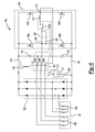
- FIG 6 is an embodiment of a brushless DC drive circuit 100 included in BLDC controller 73 ( Figure 5 ).
- Circuit 100 is ideally suited for use in a portable electric power generator, however, it will be appreciated that the invention is not so limited and may find utility in a variety of related power generating applications.
- Circuit 100 is electrically connected to PMG 52 (shown in Figure 5 ) which is a three phase permanent magnet generator having first 3-phase windings 52a for running PMG 52 in the 'Generator Mode' and second 3-phase windings 52b for running PMG 52 in the 'Motor Mode'.
- PMG 52 In 'Generator Mode', PMG 52 outputs electrical power, such as to a load 108, while in 'Motor Mode' PMG 52 rotates IC engine 14 (shown in Figure 5 ).
- PMG 52 provides a three phase AC output signal to a controlled full wave bridge rectifier circuit 122.
- Rectifier circuit 122 is coupled across DC bus lines, or rails, 128 and 134 that form a DC bus.
- a full H-bridge circuit 140 comprising four identical power switching devices 146a-146d.
- An inductor 152 and a capacitor 158 are coupled across nodes 164 and 170 and form an LC filter for attenuating harmonic distortion in the output waveform generated by the H-bridge 140.
- Each of the power switching devices 146a-146d may comprise a variety of suitable power switching components, for example field effect transistors (FET's) or insulated gate bi-polar transistors (IGBT's).
- a pair of DC bus capacitors 176 and 182 are also coupled in series across the DC bus rails 128 and 134. Although the DC bus capacitance is shown to only include the pair of capacitors 176 and 182, it is envisioned that the DC bus capacitance could comprise any even number of capacitors.
- One phase of second windings 52b is connected at a center node between even numbers of the DC bus capacitors.
- DC drive circuit 100 includes a 4-pole relay switch 194 that includes four poles 200a-200d and a coil 218.
- Universal battery pack 12 is removably inserted in series with key switches 206 and 212 between DC bus lines 128 and 134.
- the power switching devices 146a-146d are sequenced by signals from a Hall effect position sensor (not shown) and coupled, via an AND gate (not shown), with a pulse width modulated (PWM) signal. Power switching devices 146a-146d create two phases of a three phase drive signal used to drive PMG 52 as a brushless DC motor with capacitors 176, 182 creating the third phase.
- PWM pulse width modulated
- the PWM signal is based on the rated voltage output of universal battery pack 12.
- the rated voltage output of universal battery pack 12 need not conform to one predetermined DC voltage.
- the rated voltage output of universal battery pack 12 can be, for example, a voltage preferably of 12 volts or greater, preferably ranging from 12 to 18 volts.
- a NiCd universal battery pack of 12, 14.4 or 18 volts can be utilized with circuit 100 and regardless of the output voltage, the effective voltage provided to PMG second windings 52b will be approximately equal to that of a 12 volt battery.
- relay coil 218 is energized to disconnect second windings 52b from H-bridge circuit 140 and bus capacitors 176 and 182 and to connect load 108 to the output of H-bridge circuit 140.
- PMG 52 is switched to 'Generator Mode'.
- PMG 52 outputs variable voltage, variable frequency AC power, via first windings 52a.
- Full wave bridge rectifier circuit 122 and H-bridge circuit 140 convert the AC power to a constant voltage, constant frequency output, for example a 120 VAC, 60 Hz, that is output from H-bridge circuit 140 to load 108.
- universal battery pack 12 can be any universal battery pack commonly used in many cordless power tools, for example the DEWALT XR PLUS (Extended Run Time Plus) line of batteries.
- FIG 7 is a simplified schematic drawing of a preferred embodiment of a brushless DC motor drive circuit 250 included in BLDC controller 72 used in portable generator system 70 (shown in Figure 4 ).
- Drive circuit 250 is used to drive PMG 52 as a brushless DC motor to start IC engine 14 (shown in Figure 4 ).
- Circuit 250 is a low voltage DC to AC 3-phase inverter that incorporates a Brushless DC/Permanent Magnet Generator (BLDC/PMG) starter control 256, and is powered directly by universal battery pack 12.
- DC drive circuit 250 includes a power stage 262 that is electrically connectable to PMG 52 through a 3-pole relay switch 268.
- Power stage 262 includes six identical power switching devices 274a - 274f coupled across DC bus lines, or rails, 280 and 286.
- Power switching devices 274a and 274b are connected in series between bus lines 280 and 286 having a center node 298 electrically connected to one pole of relay 268.
- Power switching devices 274c and 274d are connected in series between bus lines 280 and 286 having a center node 304 electrically connected to a second pole of relay 268.
- Power switching devices 274e and 274f are similarly connected in series between bus lines 280 and 286 having a center node 310 electrically connected to a third pole of relay 268.
- Six diodes 292a - 292f are respectively connected in parallel with switching devices 274a-274f, between bus lines 280 and 286.
- Switching devices 274a - 274f may comprise a variety of suitable power switching components, for example field effect transistors (FET's), insulated gate bi-polar transistors (IGBT's), or metal oxide silicon field effect transistors (MOSFET's).
- FET's field effect transistors
- IGBT's insulated
- the 3-phase PMG 52 includes position sensors 320, 322 and 324, which are illustratively Hall effect sensors, that are connected to BLDC/PMG starter control 256 by lines 314, 316 and 318, respectively. Position sensors 320, 322, 324 sense the position of a rotor (not shown) of PMG 52. Additionally, DC drive circuit 250 includes a momentary starter switch 330 that controls the flow of current from universal battery pack 12 to BLDC/PMG starter control 256.
- IC engine 14 In operation, initially IC engine 14 is at rest. The IC engine 14 is started by a user closing momentary start switch 330. The BLDC/PMG starter control 256 will then become energized by universal battery pack 12. Provided the position sensors 320, 322 and 324 indicate that either the speed of IC engine 14 or the speed of PMG 52 is less than a predetermined value, e.g. 600 rpm, 3-pole relay switch 268 will be energized by BLDC/PMG starter control 256, thereby connecting the 3-phase power stage 262 to PMG 52. Utilizing information from position sensors 320, 322 and 324, the switching devices 274a - 274f are turned on and off by BLDC/PMG starter control 256. The switching of switching devices 274a-274f electronically commutates second 3-phase windings 52b within PMG 52 to drive PMG 52 as a brushless DC motor to rotate IC engine 14 to start it.
- a predetermined value e.g. 600 rpm
- IC engine 14 when PMG 52 is in 'Motor Mode', IC engine 14 will be turned by PMG 52 acting as a motor and will accelerate up to a speed to start IC engine 14. Once IC engine 14 has started, PMG 52 is driven past a predetermined maximum speed, e.g. 600 rpm, and 3-pole relay switch 268 will then be de-energized, thereby disconnecting power stage 262 from PMG 52. Disconnecting power stage 262 avoids overdriving universal battery pack 12 and supplying excessive voltage to switching devices 274a - 274f. Once the starting operation is complete, momentary starter switch 330 is opened.
- a predetermined maximum speed e.g. 600 rpm
- BLDC/PMG starter control 256 can be microprocessor based to simplify the electronic circuitry and to provide additional control features. Additional control features may include setting a maximum cranking time, e.g. 5 seconds, to avoid damage if momentary starter switch 330 is held closed for too long, or not attempting starting of IC engine 14 when universal battery pack 12 does not have sufficient voltage to turn or start IC engine 14. Further control features provided by a microprocessor based BLDC/PMG starter control 256 may include speed detection and control of 3-pole relay switch 268 to avoid overdriving universal battery pack 12 and power stage 262. Even further control features may include setting an upper starting speed of PMG 52 regardless of the voltage of universal battery pack 12 by utilizing pulse width modulation control of switching devices 274a - 274f above a minimum speed.
- a maximum cranking time e.g. 5 seconds
- PMG 52 includes a single set of tapped windings.
- the first windings 52a comprise the full windings, which are used to generate AC power in the 'Generator Mode'.
- the second windings 52b comprise the tapped portion of the windings, which are used to drive PMG 52 as a motor in the 'Motor Mode' to start the IC engine 14.
- the present invention has been shown and described in connection with a portable generator using a single PMG and a single alternator/inverter circuit, or a single brushless DC drive circuit, the present invention could just as readily be adapted for use with starter systems of portable generators utilizing a pair of PMG's and a pair of alternator/inverter circuits.
- the present invention could be used with a portable generator using a pair of PMG's with a pair of brushless DC motor drive circuits, such as that described in patent application 10/077,386, filed February 15, 2002 , entitled Alternator/Inverter With Dual H-Bridge and Automatic Voltage Regulation, herein incorporated by reference in its entirety.
- the invention is further applicable to all types of small IC engines, for example a lawnmower engine. Thus, the scope of the invention should not be construed as being limited only to portable generators.
- the present invention thus provides a means for starting an internal combustion engine utilizing a universal battery pack, wherein the universal batter pack is able to be used with other cordless power tools. Also, by controlling an H-Bridge switching circuit in a predetermined switching sequence, the H-Bridge can be used to control the application of power to a PMG to enable the PMG to be effectively used as a starter motor to start the internal combustion engine.
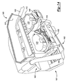
- FIG 8 shows a portable generator 800 in accordance with an aspect of the invention.
- a portable generator has an electric generator device for generating AC power that is driven by an internal combustion engine and is sufficiently light that it can be manually moved from one place to another.
- Portable generator 800 includes a frame 802 that supports an internal combustion engine 804.
- Frame 802 may illustratively support wheels 805 (only one of which is shown in Figure 8 ) and include handles 807 to facilitate manually moving portable generator 800.
- An electric generator device (hidden from view in Figure 8 ) is coupled to an output shaft of internal combustion engine 804.
- the electric generator device generates AC power, such as has been described above.
- the AC power may illustratively be 120 VAC (or 110 or 115 VAC) and may also illustratively be 240 VAC (or 220 or 230 VAC). It may be 60 Hz, or may be 50 Hz.
- Portable generator 800 further includes a control panel 806, shown in more detail in Figs. 9 and 10 .
- control panel 806 includes AC outlets 900.
- AC outlets 900 illustratively include ground fault interrupter outlets 902 and twist-lock outlets 904.
- Control panel 806 also includes on/off/start switch 906, circuit breakers 908, and idle speed control switch 910.
- Control panel 806 further includes battery receptacle 912 electrically coupled to an electrically powered starting device for starting internal combustion engine 804, such as the starting devices described above.
- Battery receptacle 912 may illustratively be a "foot" of a cordless power tool that receives a battery pack, such as battery pack 1100 ( Figure 11 ).
- a "foot" of a cordless power tool is that portion of the power tool, typically part of the power tool's housing, that is configured to receive a battery pack.
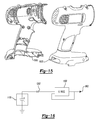
- battery pack 1100 may be a battery pack for the DEWALT series of 18 volt cordless power tools and battery receptacle 912 would then illustratively be materially the same as the foot of these power tools, such as the DEWALT DW959K-2 drill.
- FIG. 15 shows housing halves 1500 of the DEWALT DW959K-2 drill, the lower portions of which comprise the foot of this cordless power tool. It should be understood, however, that battery receptacle 912 could be the foot of any cordless power tool that uses a removable battery pack.
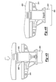
- battery receptacle 912 illustratively includes housing halves 914 mated together to form a housing 915.
- a collar 917 illustratively a rectangular shaped collar, surrounds housing 915 and includes screw posts 1200 (only one of which is shown in Figure 12 ) for receiving screws which secure collar 917 to control panel 806.
- Housing 915 includes a base portion 919 having an outer plate 916 that conforms to an upper plate 1102 of battery pack 1100 ( Figure 11 ) and a columnar portion 1218 ( Figure 12 ) extending from base portion 919.
- Opposed flanges 1214 ( Figure 12 ) project outwardly from housing halves 914 at opposed edges of outer plate 916.
- Opposed flanges 1214 include slots 1216 therein that mate with inwardly extending projections 1300 ( Figure 13 ) of collar 917 to secure housing 915 to control panel 806 when collar 917 is secured to control panel 806.
- Housing 915 has a bore or passageway 918 therein that conforms to a tower 1104 of battery pack 1100 that extends from a base 1101 of battery pack 1100.
- Battery receptacle 912 further includes opposed catches 920 at opposed sides of outer plate 916 which mate with latches 1106 (only one of which is shown in Figure 11 ) of battery pack 1100.
- Catches 920 illustratively include slots 922 that receive projections 1108 of latches 1106 of battery pack 1100.
- latches 1106 of battery pack 1100 are spring latches in which buttons 1110 of latches 1106 are depressed to retract projections 1108 from slots 922 of catches 920.
- Housing 915 of battery receptacle 912 further includes a keyway 924 in outer plate 916 projecting from bore 918 that receives a key 1124 at the base of tower 1104 of battery pack 1100.
- Battery receptacle 912 further includes a connector 1202 ( Figure 12 ) that mates with terminal block 1112 of battery pack 1100.
- Connector 1202 is electrically coupled to a starting device for internal combustion engine 804 in a manner similar to that described above.
- Terminal block 1112 of battery pack 1100 includes power terminals 1114, 1116, temperature sense terminal 1118 (which is connected to a temperature sensing element within battery pack 1100 such as a thermistor) and key 1120 surrounded by a rectangular wall 1122 having a key 1124 projecting outwardly from an end wall.
- Connector 1202 has corresponding power terminals 1204, 1206.
- Terminals 1204, 1206 are spaced from each other and have a space 1208 therebetween which receives temperature sense terminal 1118 and key 1120.
- Terminals 1204, 1206 are surrounded by a rectangular wall 1212. It should be understood that connector 1202 could have a female temperature sense terminal (not shown) if generator 800 includes circuitry to sense the temperature of battery pack 1100.
- Housing halves 914 include opposed channels 1210 that receive opposed flanges of connector 1202 to mount connector 1202 in housing 915.
- a user of generator 800 can advantageously use the battery pack for the cordless power tool, such as battery pack 1100, in starting generator 800.
- battery pack 1100 is not charged by generator 800. Rather, when battery pack 1100 needs charging, it is charged in an external charger, such as the external charger that is typically provided with the cordless power tool when the user purchases the cordless power tool.
- generator 800 does not require its own battery, which is typically a lead acid type of battery.
- the user need not purchase the lead acid battery, avoids the need to maintain such a lead acid battery, and generator 800 is lighter since the weight of the lead acid battery is eliminated.
- FIG 14 shows another aspect of the invention.
- a portable electric generator 1400 includes a frame 1402 that supports an internal combustion engine 1404.
- Frame 1402 may illustratively support wheels 1401 (only one of which is shown in Figure 8 ) and include handles 1403 for facilitating moving generator 1400.
- An electric generator device (hidden from view in Figure 14 ) is coupled to an output shaft of internal combustion engine 1404.
- the electric generator device generates AC power, such as has been described above.
- the AC power may illustratively be 120 VAC (or 110 or 115 VAC) and may also illustratively be 240 VAC (or 220 or 230 VAC). It may be 60 Hz, or may be 50 Hz.
- Generator 1400 also includes a control panel including AC outlets (not shown in Figure 14 ).
- Generator 1400 further includes enclosure 1406 mounted to frame 1402.
- Base portion 1408 of enclosure 1406 includes battery receptacle 1412, charger 1414 and AC outlet 1416.
- Battery receptacle 1412 is configured to receive a battery pack from a cordless power tool, such as battery pack 1100.
- battery receptacle 1412 may be configured to receive a tower type of battery pack, such as battery pack 1100, as is charger 1414.
- battery receptacle 1412 may illustratively have a configuration similar to battery receptacle 912 described above.
- Battery receptacle 1412 may alternatively be configured to receive a rail type of battery pack, such as battery pack 16 shown in U.S. 6,653,815 , the disclosure of which is incorporated herein in its entirety by reference.
- battery receptacle 1412 has a configuration similar to that on the foot of tool 10 of U.S. 6,653,815 . That is, battery receptacle 1412 includes a pair of grooves that receives guide rails of the rail type battery pack. It also includes a connector configured to mate with the terminal block of the rail type battery pack.
- Charger 1414 may illustratively be a stand alone charger such as the charger that is typically supplied with the power tool when the user purchases the power tool and is thus mounted in base portion 1408 of enclosure 1406 and plugged into AC outlet 1416 in enclosure 1406.
- Charger 1414 may illustratively be a multi-port charger having a plurality of ports to that charger 1414 can receive a plurality of battery packs 1100 at any one time to charge them simultaneously.
- Battery receptacle 1412 is electrically coupled to an electrically powered starting device for starting internal combustion 1404, such as the starting devices described above.
- a battery pack such as battery pack 1100
- a cordless power tool is placed in battery receptacle 1412 and provides electrical power to start internal combustion engine 1404.
- Charger 1414 is used to charge one or more battery packs 1100.
- the battery pack 1100 in battery receptacle 1412 can be removed from battery receptacle 1412 and placed in charger 1414 to charge that battery pack 1100.
- Internal combustion engine 1404 may have a pull start that can be used to start internal combustion engine 1404 as well as the electrical starter circuit described above. The pull start could then be used to start internal combustion engine 1404 when the battery pack 1100 is discharged. Battery pack 1100 can then be placed in charger 1414, charged, and then placed in battery receptacle 1412 to provide electrical power to the electrical starting device so that internal combustion engine can be electrically started.
- portable generator 800 is adapted to use universal battery packs having different voltages. More specifically with reference to Figure 16 , portable generator 800 includes a voltage regulation circuit 1600 that couples connector 1202 of battery receptacle 912 to the starting device for internal combustion engine 804, thus coupling the output of battery pack 1100 to the starting device for internal combustion engine 804 when battery pack 1100 is received in battery receptacle 912.
- Voltage regulation circuit 1600 illustratively provides at its output 1602 a set voltage at the appropriate level for the starting device for internal combustion engine 804. For example, if the starting device for internal combustion engine 804 utilizes a 12 volt DC starter motor, then voltage regulation circuit 1600 provides 12 volts DC at its output 1602. Voltage regulation circuit 1600 may illustratively monitor the voltage at its output 1602 and adjust its output accordingly to maintain the appropriate voltage level.
- Voltage regulation circuit 1600 may be any known type of voltage regulation circuit. It may, for example, be a DC-DC converter in which the switching device(s) in the DC-DC converter are switched with a pulse width modulated signal and the duty cycle of the pulse width modulated signal is controlled to obtain the desired voltage level at output 1602. That is, voltage regulation circuit 1600 compares the voltage at its output 1602 with the desired voltage and adjusts the duty cycle of the PWM signal to maintain the output voltage constant at the desired level.
- Voltage regulation circuit 1600 may illustratively be a buck converter type of DC-DC converter. Since buck converters are step-down converters, the starter motor used would then illustratively be a low voltage starter motor such that the voltage of the starter motor is no greater than the lowest voltage universal battery pack utilized.
- voltage regulation circuit 1600 may illustratively be a boost converter type of DC-DC converter. Since boost converters are step-up converters, the starter motor used would then illustratively be a higher voltage starter motor such that the voltage of the starter motor is no lower than the highest voltage universal battery pack utilized.
- Voltage regulation circuit 1600 may also illustratively be a buck-boost type of DC-DC converter which can both step-up and step-down. The starter motor utilized can then have a voltage that falls between the voltage of the highest voltage universal battery pack utilized and the voltage of the lowest voltage universal battery pack utilized. It should be understood that generator 1400 can similarly have voltage regulation circuit 1600.
- the generator system 1610 utilizes a battery pack 1612 that is mounted to generator system 1610 with fastening devices, such as one or more hold down members shown representatively by 1617.
- Hold down member(s) 1617 may be removably affixed to housing 1616 such as with screws (not shown).
- Battery pack 1612 is thus "permanently mounted” in housing 1616 in the sense that it is not easily removable by hand. But battery pack 1612 can be removed and replaced in the event of failure, such as by unfastening hold down member(s) 1617, removing and replacing back pack 1612, and refastening hold down member(s) 1617.
- Battery pack 1612 may comprise a battery pack such as the battery pack 1100 ( Figure 11 ). Further, battery pack 1612 may comprise any suitable battery pack such as a NiCad universal battery pack of 12, 14.4 or 18 volts. In this example however, the battery pack 1612 is permanently mounted within a housing 1616 mounted in a frame of generator system 1610, such as frame 1402 ( Figure 14 ). The housing 1616 may define similar components as described with respect to the enclosure 1406 ( Figure 14 ), but in this example, the housing 1616 surrounds the battery pack 1612. The housing 1616 may include any suitable containment structure.
- the housing 1616 may provide a removable portion, such as a door or cover plate 1620 to gain access to the battery pack 1612 in the event the battery pack 1612 needs to be replaced.
- the cover plate 1620 may be removably secured to the housing 1616, such as by fasteners (not shown).
- a charging circuit 1630 may be provided.
- the charging circuit 1630 may be electrically connected to the power generating device 16 whereby the power generating device may provide the charging circuit with power to charge the battery pack 1612. It should be appreciated that while the charging circuit 1630 is specifically illustrated for use with the generator system 1610, it may easily be adapted for use in any of the generator systems disclosed herein. Charging circuit 1630 would illustratively be switched off during starting internal combustion engine 10 of generator system 1610 and then switched on after internal combustion engine 10 is started.
- the generator system 1610 utilizes battery pack 1612 to start the IC engine 14 that turns the power generating device 16.
- the generator system 1610 may additionally include a starting device 18 connected to the battery pack 1612 and the starter switch.
- the starting device 18 may comprise any suitable starting device such as a starter motor and tarter solenoid (see e.g., Figure 2 ).
- the starter switch 20 may be connected to the transistorized ignition unit 24, which is in turn connected to a the spark plug 26.
- the staring device 18 may be used to turn the IC engine 14 at a rate sufficient to start the IC engine 14.
- the IC engine 14 drives power generating device 16.
- the power generating device 16 may output AC power usable by a load connected to the electrical outlet. Concurrently, the power generating device may provide power to the charging unit 1630 to charge the battery pack 1612.
- the power generator device may alternatively comprise a generator alternator ( Figure 2 ).
- the portable generator system 1800 includes an actuator switch 1802.
- the actuator switch 1802 is switchable to provide electrical connection between the universal battery pack 12 and the starting device 18 or between universal battery pack 12 and the charging circuit 1630.
- a user may place the universal battery pack 12 into the battery receptacle (such as battery receptacle 912, Figure 9 ) and switch the actuator switch to a 'Start' position, thereby electrically coupling the universal battery pack 12 to the starting device 18.
- the starter switch 20 may also be placed into the 'Start' position such that the universal battery pack 12 provides power to the starting device 18 (such as a starter solenoid 34, Figure 2 ). While the universal battery pack 12 has been shown, it is appreciated that alternatively, the permanently mounted battery pack 1612 in housing 1616 ( Figure 17 ) may be used.
- the spring loaded starter switch 20 may return to the 'ON' position. In the 'ON' position, the starter switch may direct power from the ignition unit 24 to the spark plug 26. Each time spark plug 26 fires, spark is provided to IC engine 14, which is utilized to ignite a compressed fuel and air mixture present in a cylinder (not shown) during a compression cycle of IC engine 14. When IC engine 14 is running it turns alternator 36, which creates an output voltage usable to provide AC power at outlet 22.
- the actuator switch 1662 may be moved to a 'Charge' position. In the 'Charge' position, the actuator switch 1662 may electrically connect the charging circuit 1630 to universal battery pack 12 to charge the universal battery pack 12. It is contemplated that the actuator switch 1662 may be spring-loaded so that it returns to the 'Charge' position upon successfully starting the IC engine 14. It is also contemplated that the operation of the actuator switch 1662 and the starter switch 20 may be combined into a single switch. In this way, a single start switch of the generator system 1660 may be wired such that charging is deactivated when the start switch is turned to the 'Start' position and then reactivates charging when the momentary start switch is released.
- the portable generator 1700 may include the frame 1402 that supports the IC engine 1404.
- the frame 1402 may illustratively support wheels 1401 ( Figure 8 ), and include handles 1403 for facilitating moving the generator 1700.
- An electric generator device (hidden from view in Figure 14 ) may be coupled to an output shaft of internal combustion engine 1404.
- the electric generator device generates AC power, such as has been described above.
- the AC power may illustratively be 120 VAC (or 110 or 115 VAC) and may also illustratively be 240 VAC (or 220 or 230 VAC). It may be 60 Hz, or may be 50 Hz.
- Generator 1700 may also include a control panel including AC outlets (not shown in Figure 14 ).
- the Generator 1700 further includes enclosure 1706 mounted to frame 1402.
- the enclosure 1706 which may illustratively be a water resistant enclosure, includes a rectangular tub shaped base portion 1408 and hinged lid 1710 including biasing members 1712.
- the biasing member 1712 urge the batteries 1100 into the respective battery receptacle 1412 and charger 1414 when the hinged lid 1710 is in a closed position.
- the biasing member 1712 may comprise any biasing structure such as a leaf spring for example.
- a pair of latches 1720 may be provided on the hinged lid 1710 for securably coupling to a pair of hooks 1722 provided on the base portion 1408 when hinged lid 1710 is in the closed position.
- the base portion 1408 of enclosure 1406 includes battery receptacle 1412, charger 1414 and AC outlet 1416.
- Battery receptacle 1412 is configured to receive a battery pack from a cordless power tool, such as battery pack 1100.
- battery receptacle 1412 may be configured to receive a tower type of battery pack, such as battery pack 1100, as is charger 1414.
- battery receptacle 1412 may illustratively have a configuration similar to battery receptacle 912 described above.
- Battery receptacle 1412 may alternatively be configured to receive a rail type of battery pack, such as battery pack 16 shown in U.S. 6,653,815 , the disclosure of which is incorporated herein in its entirety by reference.
- battery receptacle 1412 has a configuration similar to that on the foot of tool 10 of U.S. 6,653,815 . That is, battery receptacle 1412 includes a pair of grooves that receives guide rails of the rail type battery pack. It also includes a connector configured to mate with the terminal block of the rail type battery pack.
- the hinged lid 1710 is shown in the closed position.
- the biasing members 1712 engage an upper surface of the battery packs 1100 and urge them downward into the receptacles 1412 and charger 1414.
- electrical connection of battery packs 1100 in receptacle 1412 and charger 1414 may be maintained during movement of the generator system 1700 such as by physical movement of the generator system 1700 as a whole or by vibratory movement communicated by the IC engine 14 during use.
- the biasing members 1712 may additionally be provided on the housing 1616 disclosed for use with the permanent battery pack 1612 ( Figure 17 ).
- the adapters 1750 and 1752 each have insertion portions 1760 and 1762, respectively for receipt into battery receptacles 912 ( Figures 8-10 ) and/or 1412 ( Figures 14 , 19 and 20 ).
- the adapter 1750 has a battery receptacle portion 1770 while the adapter 1752 has a battery receptacle portion 1772.
- Terminals 1776 may be located in the battery receptacle portion 1772 for electrical communication with a battery pack (not shown) received into the adapter 1752 in the battery receptacle portion 1772.
- the adapters may be selectively inserted into any of the battery receptacles 912, and/or 1412 enabling battery receptacles 912 and or 1412 to accept battery packs having different footprints.
- these battery packs may be battery packs for use with power tools such as for different brands of power tools.
- Footprint as used with respect to a battery back relates to a battery receptacle portion 1772 of adapter 1752 means that part of the battery pack that is received in the battery receptacle portion 1772.
- the respective battery receptacle portions 1770 and 1772 may define complementary geometry to accept battery packs having a footprint distinct from the tower 1104 of the DEWALT battery pack 1100 described in the examples above ( Figure 11 ).
- a desired adapter 1750 or 1752 may be selectively inserted into battery receptacle 912, and/or 1412.
- the insertion portions 1760 and 1762 mate with the receptacles 912 and/or 1412 similar to a battery pack 1100.
- a battery pack (not shown) having complementary mating structure with the battery receptacle portions 1770 or 1772 may be selectively inserted into the adapter 1750, 1752.
- the additional height realized by using the adapter 1750, 1752 may be accommodated by the biasing member 1712.
- other biasing members and/or hinged lids 1710 may be provided to accommodate various geometry battery packs.
- FIG. 23 shows a compressor 2300 in accordance with an aspect of the invention.
- the compressor 2300 may incorporate any of the features discussed herein with respect to the portable generators 800 and/or 1400.
- the compressor 2300 includes a frame 2302 that supports an internal combustion engine 2304, an output device such as air compressor 2306 driven by the internal combustion engine 2304, and an air tank 2305 coupled to an output of the air compressor 2306.
- a battery receptacle 2312 may be electrically coupled to an electrically powered starting device for starting the internal combustion engine 2304 and/or charging the battery, such as the starting devices and charging circuits described above. In this way, the power generating device 16 may be replaced with an output device such as the air compressor 2306, or other associated output of the compressor 2300.
- FIG. 24 shows a power washer 2400 in accordance with an aspect of the invention.
- the power washer 2400 may incorporate any of the features discussed herein with respect to the portable generator 800 and/or 1400.
- the power washer 2400 includes a frame 2402 that supports an internal combustion engine 2404 and an output device such as a pump 2406 driven by the internal combustion engine 2404.
- An output of pump 2406 is coupled to a movable spray wand 2405.
- a battery receptacle 2412 may be electrically coupled to an electrically powered starting device for starting the internal combustion engine 2404 and/or charging the battery, such as the starting devices and charging circuits described above.
- the power generating device 16 may be replaced with an output device such as a pressure regulating device, spray wand 2405, or other associated output of the power washer 2400.
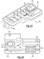
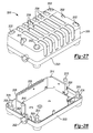
- Control panel 806 includes top plate 2500 and housing 2502.
- Control panel 806 is illustrated in Figure 26 .
- Housing 2502 has a depth sufficient to receive a battery pack, such as battery pack 1100, in battery receptacle 912.
- Housing 2502 provides an enclosure for charger assembly 2510, battery receptacle 912 and their associated connections (not shown in figures).
- Top panel 2500 and housing 2502 may be made of any suitable rigid material, e.g., stainless steel.
- Control panel housing 2502 further includes a plurality of fastener holes 2504 for mounting the control panel 806 to frame 802 of portable generator 800, as illustrated in Figure 8 . Additional fastener holes 2504 may be utilized to secure top panel 2500 to housing 2502.
- Charger assembly 2510 is formed of base 2520 and cage 2530.
- Charger assembly base 2520 includes a wire collar 2522 and charger protection plate 2526 with associated plurality of fingers 2528.
- Base 2520 and cage 2530 are secured together with a plurality of fasteners 2515.
- Fasteners 2515 are inserted through fastener openings 2532 in cage 2530 and received in fastener receptacles 2524 of base 2520.
- Fasteners 2515 may comprise, for example, rivets, screws or other similar fastening devices. The use of fasteners 2515 fixedly secures the base 2520 with the cage 2530 of charger assembly 2510.
- a charger and associated charging circuitry (not shown) is received within charger assembly 2510, that is, substantially enclosed between base 2520 and cage 2530.
- Charger protection plate 2526 and plurality of fingers 2528 help secure the charger within charger assembly 2510, as well as provide protection to the charger itself.
- the cage 2530 of charger assembly 2510 may include a plurality of ribs 2536 arranged to define a plurality of cage vent openings 2534 to provide ventilation to the charger and its associated circuitry.
- Wire collar 2522 of base 2520 provides an opening for the wire of the charger to exit the charger assembly 2510. Furthermore, wire collar 2522 reduces the strain on the wire of the charger.
- the wire of the charger may be directly coupled to the output of the power generating device 16 or, alternatively, may exit the housing 2502 and end in a plug that can be inserted into AC outlets 902.
- charger assembly 2510 is assembled as a complete unit and is then installed in control panel 806. This allows, by way of example and not of limitation, charger assembly 2510 to be a product supplied to the assembler of control panel 806.
- charger assembly 2510 installed in housing 2502 of control panel 806 is illustrated.
- Battery receptacle 912 is electrically connected to the charger and its associated circuitry within charger assembly 2510.
- the electrical connections between battery pack 1100 and charging circuit 1630 may include an actuator switch 1802.
- the charger of charger assembly 2510 may comprise a stand alone charger (not shown) and/or charging circuit 1630, as illustrated in Figures 17 and 18 .
- battery pack 1100 as shown in control panel assembly 2500 may be replaced with permanent battery pack 1612, as illustrated in Figure 17 .
- control panel 806 Upon coupling top panel 2500 with control panel housing 2502, the sensitive circuitry and electrical connections of battery receptacle 912 and charger assembly 2510 are substantially enclosed.
- the control panel 806 provides protection to the charger and/or charging circuit 1630 and, in the case of permanently installed battery pack 1612, the battery pack from manipulation by the user, as well as moisture, dirt and other environmental conditions.
- an indicating mechanism can be connected at one or more suitable locations on the battery pack 1100, so as to be detected by the battery receptacle 912 to indicate a predetermined battery chemistry associated with the cells in the battery pack 1100.
- the battery receptacle 912 can detect the indicating mechanism so as to determine the chemistry of the battery pack 1100 based on the detection.
- detection of the indicating mechanism can indicate the predetermined battery chemistry, e.g., a lithium ion ("Li-Ion”) battery chemistry.
- the inability to detect the indicating mechanism can indicate a different predetermined battery chemistry, e.g., a nickel cadmium (“Ni-Cad”) battery chemistry.
- a nickel cadmium nickel metal hydride
- lithium ion zinc-carbon
- zinc-chloride zinc-chloride
- alkaline zinc-manganese dioxide
- mercury oxide zinc-air, silver oxide, etc.
- the battery receptacle 912 can also detect a data signal from a data connection (not shown) in the terminal block 1112 to further confirm the battery chemistry of the battery pack 1110. Specifically, detection of both the indicating mechanism and the data signal from the data connection can indicate the predetermined battery chemistry, e.g., a lithium ion ("Li-Ion”) battery chemistry. The inability to detect either the indicating mechanism or the data signal from the data connection, in contrast, can indicate a different predetermined battery chemistry, e.g., a nickel cadmium (“Ni-Cad”) battery chemistry.
- the indicating mechanism can be located in the terminal block 1112 and can be configured to be similar to the power terminals 1114, 1116 and/or the data connection.
- the indicating mechanism can be referred to as a fourth terminal.
- the power terminals 1114, 1116 comprise the first and second terminals
- the data connection can comprise a third terminal, so that the indicating mechanism can be the fourth terminal.
- the terminal block 1112 can contain a fourth terminal used for purposes other than that described above, such that the indicating mechanism can be located at other locations on the battery pack 1110 and, in various instances, outside of the terminal block 1112.
- the indicating mechanism can be referred to as a fifth terminal, or whatever terminal, connection, etc. may be applicable based on the configuration of the battery pack 1110. It will be appreciated that the indicating mechanism can be located at various locations on the battery packs regardless of whether the battery pack 1110 is provided with a rail configuration or the tower configuration illustrated in FIG. 11 .
- an indicating mechanism 1150 is shown associated with a battery pack 1152 and a battery receptacle 1154.
- the indicating mechanism 1150 can be configured so as to include a spring member 1156 that can extend from the battery receptacle 1154 and contact the battery pack 1152.
- the spring member 1156 can contact a connector 1158 on the battery pack 1152 so that, for example, a reference voltage can be detected by the battery receptacle 1154 and/or the battery pack 1152. Detecting the indicating mechanism 1150, therefore, can include detecting the reference voltage.
- the spring member 1156 can contact the connector 1158 on the battery pack 1152 so that, for example, continuity can be detected by the battery receptacle 1154 and the battery pack 1152.
- detecting the indicating mechanism 1150 can, therefore, include detecting continuity.
- the indicating mechanism 1150 can include a spring member 1156 that can extend from the battery receptacle 1154 and contact the battery pack 1152.
- the spring member 1156 can contact a portion of the battery pack 1152 so that, for example, deflection of the spring member 1156 can activate a switch (e.g., a micro switch) and/or one or more suitable mechanical or electromechanical devices. Detecting the indicating mechanism 1150 can, therefore, include detecting a signal from the switch activated by the indicating mechanism 1150.
- an example of an indicating mechanism 1160 is shown associated with a battery pack 1162 and a battery receptacle 1164.
- the indicating mechanism 1160 can include a spring member 1166 that can extend from the battery pack 1162 and contact the battery receptacle 1164. Similar to the indicating mechanism 1150 in FIG. 29 , the spring member 1166 can contact a connector 1168 on the battery receptacle 1164 so that, for example, a reference voltage or continuity can be detected. In addition, the spring member 1166 can activate a switch as explained above.
- the indicating mechanism 1170 can include an emitter 1176 and a receiver 1178.
- detecting the indicating mechanism 1170 can, therefore, include detection of one or more electromagnetic wave signals 1180 from the emitter 1176 by the receiver 1178.
- the emitter 1176 can be one or more members that can produce a magnetic field (e.g., a magnet, an electromagnet, etc.).
- the receiver 1178 can be a hall-effect sensor. Detection of the indicating mechanism 1170 can, therefore, include the hall-effect sensor detecting the one or more members that produce the magnetic field.
- the emitter 1176 can emit a radio frequency (RF) signal that can be received (i.e., detected) by the receiver 1178.
- detection of the indicating mechanism 1170 can, therefore, include the receiver 1178 detecting the RF signal from the emitter 1176.
- the emitter 1176 can be located in or on the battery pack 1172 and the receiver 1178 can be located in or on the battery receptacle 1174 or vice versa, as applicable.
- a battery pack 2200 can include an indicating mechanism 2202.
- the indicating mechanism 2202 can be in a position that is relatively close to a terminal block 2204 that can contain a data connection and/or a communication connection (not shown).
- the indicating mechanism 2202 can be located on a tower portion 2206 outside of the terminal block 2204.
- a battery pack 2220 can include an indicating mechanism 2222 that can be located on an upper deck 2224 of a body portion 2226 of the battery pack 2220. It will be appreciated in light of the disclosure that the positioning of the indicating mechanism 2222, in the example illustrated in FIG. 33 , can be at a greater distance from a terminal block 2228 than the indicating mechanism 2202 relative to the terminal block 2204, as illustrated in FIG. 32 .
- FIGS. 32 - 39 can include locations of the indicating mechanism that can maximize a distance between a terminal block and the indicating mechanism.
- the distance between the terminal block and the indicating mechanism can be maximized for various reasons.
- One reason can be shown to include avoiding obstructing the power connection, the data connection and the indicating mechanisms with, for example, a paint spill or other debris from the work site.
- the propensity somehow obstruct, cover, deactivate, etc. both the data connection and the indicating mechanism so as to not detect the data connection and/or the indicating mechanism as a proxy for a predetermined battery chemistry can be reduced.
- a battery pack 2240 can include an indicating mechanism 2242 that can be positioned on a lower deck 2244 of the battery pack 2240.
- FIG. 35 illustrates an example of an indicating mechanism 2250 being on a side area 2252 of a battery pack 2254. While the indicating mechanism 2250 is illustrated on the side area 2252 of a base portion 2256, it will be appreciated in light of the disclosure that the indicating mechanism 2250 can be on a side of a tower portion 2258 in lieu of the base portion 2256.
- a battery pack 2260 can include an indicating mechanism 2262 being on a side area 2264 of the battery pack 2260. While the indicating mechanism 2262 is illustrated on the side area 2264 of a tower portion 2266, it will be appreciated in light of the disclosure that the indicating mechanism 2262 can be on the side area 2264 of a base portion 2268 in lieu of the tower portion 2266. Moreover, the side area 2264 of the tower portion 2266 on which the indicating mechanism 2262 is located can be opposite the surface relative to the location of the indicating mechanism 2202 on the battery pack 2200, as illustrated in FIG. 32 .
- a battery pack 2270 can include an indicating mechanism 2272 that can be located on a front area 2274 of the battery pack 2270. While the indicating mechanism 2272 is illustrated on the front area 2274 of a base portion 2276, it will be appreciated that the indicating mechanism 2272 can be on the front area 2274 of a tower portion 2278 in lieu of the base portion 2276.
- a battery pack 2280 can include an indicating mechanism 2282 being on a rear area 2284 of the battery pack 2280. While the indicating mechanism 2282 is illustrated on the rear area 2284 of a tower portion 2286, it will be appreciated that the indicating mechanism 2282 can be on a rear area 2284 of a base portion 2288, in lieu of the tower portion 2286.
- a battery pack 2290 can include an indicating mechanism 2292 that can be located on a side area 2294 of the battery pack 2290 having an enlarged tower portion 2296
- the enlarged tower portion 2296 can sometimes be referred to as a two-up or a two tower configuration. While the indicating mechanism 2292 is illustrated on the side area 2294 of one tower portion 2296, it will be appreciated in light of the disclosure that the indicating mechanism 2292 can be on various areas of the battery pack 2290 including, but not limited to, the locations provided in the above examples.
- Housing 3915 for use in conjunction with battery receptacle 912 ( FIG. 9 ) according to various embodiments of the present disclosure is illustrated.
- Housing 3915 comprises two housing halves 3914 and terminal slot part 3920. Similar to the housing 915 illustrated in FIGS. 12 and 13 , housing 3915 is adapted to mate with a battery pack of a tower configuration, such as battery pack 1100 illustrated in FIG. 11 . Housing halves 3914 are adapted to mate together with terminal slot part 3920 to form housing 3915, as shown in FIG. 40 .
- Housing 3915 is affixed to mounting plate 3916 ( FIG. 43 ) which mounts to control panel 806.
- Terminal slot part 3920 is adapted to mate with terminal block 1112 of battery pack 1100.
- terminal slot part 3920 has a complementary shape to terminal block 1112.
- Terminal slot part 3920 includes a base portion 3921 and a recess 3928. Situated within the recess 3928, terminal protrusion 3924 and keying features 3922 may extend to be substantially coplanar with base portion 3921.
- the keying features 3922 are designed to mate with complementary recesses in the battery pack 1100. Keying features 3922 provide numerous functions, including assisting with the proper insertion of the battery pack within housing 3915 and locking out incompatible batteries or compatible batteries that are inserted incorrectly (e.g., backwards).
- keying features 3922 may provide functionality similar to that of the indicating mechanism described above. For example, keying features 3922 could interact with switches or terminals in the inserted battery pack to indicate the battery chemistry of the inserted battery pack, as described above.
- Terminal protrusion 3924 provides the additional functionality of guiding the battery pack into proper mating position with terminal slot part 3920.
- Terminal protrusion 3924 also protects the charging terminals, such as power terminals 1114, 1116 and temperature sense terminal 1118 illustrated in FIG. 12 , from being touched or contacted by a user of the generator.
- the terminals are received in terminal slots 3925, which may also include keying features 3926. Keying features 3926 may act in conjunction with, or independently of, the keying features 3922 present in the recess 3928 of terminal slot part 3920.
- the opposed terminal slots 3925 include the keying features 3926.
- a magnetic sensor 4100 such as a Hall effect sensor, is received in housing 3915.
- battery pack 912 is a Li-Ion battery pack
- a magnet in battery pack 912 will align with magnetic sensor 4100 when battery pack 912 is received in housing 3915.
- a terminal board 4302 is affixed to a bottom 4300 of housing 3915.
- terminal board 4302 includes terminals that extend into terminal slots 3925 including positive terminal 4400, negative terminal 4402, and third terminal 4404.
- a negative temperature coefficient sensor 4406 is affixed to negative terminal 4402.
- third terminal 4404 connects to a temperature sensor in the NiCad battery pack.
- third terminal 4404 provides a data terminal and in conjunction with magnetic sensor 4100, is used to verify that the battery pack 912 is a Li-Ion battery pack.
- Battery pack 4500 includes terminals 4502 and keying features 4504 for mating with terminal slot part 3920.
- the terminal slot part 3920 includes terminal protrusion 3924 and keying features 3922 that mate with the terminals 4502 and keying features 4504 of battery pack 4500 when the battery pack is received within the housing.
- Figure 46 shows a battery receptacle housing half 3914 with battery pack 4500 completely inserted within housing half 3914 and terminal slot part 3920. The battery pack 4500 is inserted within terminal slot part 3920 such that the terminals 4502 mate with a terminal board 4302.
- a magnetic sensor 4100 such as a Hall effect sensor, may be present in the housing 3915. Magnetic sensor 4100 will detect the presence of a magnet 4510 in the battery pack 4500 when it is inserted into the housing 3915.
- the magnetic sensor 4100 is coupled to the electronics of the portable generator through wires 4102 in the illustrated examples, however, other means of communication (e.g., wireless communication) may be employed. Wires 4102 may be integrated within the housing 3915 or otherwise anchored in fixed relation to housing 3915.
Landscapes
- Engineering & Computer Science (AREA)
- Chemical & Material Sciences (AREA)
- General Engineering & Computer Science (AREA)
- Combustion & Propulsion (AREA)
- Mechanical Engineering (AREA)
- Manufacturing & Machinery (AREA)
- Power Engineering (AREA)
- Chemical Kinetics & Catalysis (AREA)
- Electrochemistry (AREA)
- General Chemical & Material Sciences (AREA)
- Control Of Eletrric Generators (AREA)
- Connection Of Motors, Electrical Generators, Mechanical Devices, And The Like (AREA)
- Charge And Discharge Circuits For Batteries Or The Like (AREA)
Applications Claiming Priority (1)
| Application Number | Priority Date | Filing Date | Title |
|---|---|---|---|
| US12/508,109 US8319357B2 (en) | 2002-06-06 | 2009-07-23 | Starter system for portable internal combustion engine electric generators using a portable universal battery pack |
Publications (2)
| Publication Number | Publication Date |
|---|---|
| EP2295790A2 true EP2295790A2 (de) | 2011-03-16 |
| EP2295790A3 EP2295790A3 (de) | 2017-11-29 |
Family
ID=42938263
Family Applications (1)
| Application Number | Title | Priority Date | Filing Date |
|---|---|---|---|
| EP10170046.6A Withdrawn EP2295790A3 (de) | 2009-07-23 | 2010-07-19 | Startsystem für einen tragbaren Elektrogenerator für einen Verbrennungsmotor mit einem tragbaren Universalbatteriepack |
Country Status (3)
| Country | Link |
|---|---|
| US (1) | US8319357B2 (de) |
| EP (1) | EP2295790A3 (de) |
| CA (1) | CA2709375C (de) |
Families Citing this family (34)
| Publication number | Priority date | Publication date | Assignee | Title |
|---|---|---|---|---|
| KR101180956B1 (ko) * | 2010-12-02 | 2012-09-07 | 기아자동차주식회사 | 전기 차량의 충전기 도난 방지 장치 |
| US20130051104A1 (en) * | 2011-08-23 | 2013-02-28 | Hitachi Koki Co., Ltd. | Battery Adapter and Power Source Device Employing Same |
| DE102011053028A1 (de) * | 2011-08-26 | 2013-02-28 | Krauss-Maffei Wegmann Gmbh & Co. Kg | Fahrzeugstarthilfeeinheit, Fahrzeug und Verfahren zum Betrieb einer Fahrzeugstarthilfeeinheit |
| US8864476B2 (en) * | 2011-08-31 | 2014-10-21 | Flow Control Llc. | Portable battery operated bilge pump |
| US8857138B2 (en) | 2011-11-04 | 2014-10-14 | Briggs & Stratton Corporation | Starter system for an engine |
| US8733072B2 (en) | 2011-11-04 | 2014-05-27 | Briggs & Stratton Corporation | Starter system for an engine |
| US9127658B2 (en) * | 2011-11-04 | 2015-09-08 | Briggs & Stratton Corporation | Internal combustion engine including starting system powered by lithium-ion battery |
| EP3211213B1 (de) * | 2012-04-17 | 2023-05-31 | Briggs & Stratton, LLC | Startersystem für einen verbrennungsmotor |
| US9347837B2 (en) * | 2012-04-17 | 2016-05-24 | Honeywell International Inc. | Multi-phase brushless DC motor control integrated circuit having magnetic sensor and band-gap temperature sensor formed thereon |
| US20140370743A1 (en) * | 2013-06-13 | 2014-12-18 | Jim Maesnor | External Power Supply |
| EP2844865B1 (de) * | 2013-06-20 | 2016-04-27 | Briggs & Stratton Corporation | Brennkraftmaschine mit anhand einer lithium-ionen-batterie betriebenem elektrischem startsystem |
| US10044197B2 (en) * | 2013-12-12 | 2018-08-07 | Milwaukee Electric Tool Corporation | Portable power supply and battery charger |
| US9726135B2 (en) | 2014-02-21 | 2017-08-08 | Briggs & Stratton Corporation | Snowthrower with removable self-heating starter battery pack |
| US9624891B2 (en) * | 2014-02-21 | 2017-04-18 | Briggs & Stratton Corporation | Outdoor power equipment incorporating starter battery with integrated push button |
| US9316408B2 (en) * | 2014-02-27 | 2016-04-19 | Charles Robert Justus | Energy supply module and method of assembling the same |
| JP6550672B2 (ja) * | 2014-10-29 | 2019-07-31 | 三菱重工メイキエンジン株式会社 | エンジン、および、エンジンの仕様変更方法 |
| MX2018007783A (es) * | 2016-02-22 | 2019-09-06 | Tti Macao Commercial Offshore Ltd | Sistema de hidrolavadora modular, su metodo y kit. |
| US11444464B1 (en) * | 2016-03-25 | 2022-09-13 | Goal Zero Llc | Portable hybrid generator |
| JP6399048B2 (ja) * | 2016-07-08 | 2018-10-03 | トヨタ自動車株式会社 | 車両 |
| US11105279B2 (en) * | 2017-02-17 | 2021-08-31 | Briggs & Stratton, Llc | On-demand generator starting system |
| US10255787B1 (en) * | 2017-03-10 | 2019-04-09 | Alarm.Com Incorporated | Magnetic sensor batteries |
| JP2018168750A (ja) * | 2017-03-30 | 2018-11-01 | 本田技研工業株式会社 | エンジン発電機 |
| CN110086390B (zh) * | 2018-01-25 | 2021-03-30 | 重庆和亚科技有限公司 | 提供双等级电压的发电设备和可移动式发电机组 |
| CN110086389B (zh) * | 2018-01-25 | 2021-03-30 | 重庆和亚科技有限公司 | 离网运行的发电设备和可移动式发电机组 |
| CN112585345B (zh) | 2018-08-21 | 2022-08-05 | 米沃奇电动工具公司 | 由可移除且可充电电池组供电的车辆电池搭电启动装置 |
| US11674490B2 (en) | 2018-08-30 | 2023-06-13 | Schumacher Electric Corporation | Multifunctional battery booster |
| AU2019410335B2 (en) * | 2018-12-20 | 2025-01-16 | Globe (jiangsu) Co., Ltd. | Electrical energy storage apparatus and electric tool system |
| EP3939142B1 (de) * | 2019-03-14 | 2024-01-03 | Potencia Industrial, LLC | Stromversorgungssystem und system zum starten von motoren für ein solches stromversorgungssystem |
| CN115461536B (zh) | 2020-05-07 | 2023-05-23 | 米沃奇电动工具公司 | 具有多个电池组兼容性的车辆电池跨接启动器 |
| CN213980948U (zh) | 2020-08-27 | 2021-08-17 | 康明斯电力公司 | 用于发电机组的容器 |
| CN213980949U (zh) * | 2020-08-27 | 2021-08-17 | 康明斯电力公司 | 用于发电机组的系统 |
| US11973366B2 (en) | 2020-10-20 | 2024-04-30 | Schumacher Electric Corporation | Battery booster |
| WO2022133203A1 (en) | 2020-12-18 | 2022-06-23 | Milwaukee Electric Tool Corporation | Portable power supply |
| US12592573B2 (en) * | 2021-05-24 | 2026-03-31 | Discovery Energy, Llc | Hybrid generator with detachable power unit and panel integration |
Citations (5)
| Publication number | Priority date | Publication date | Assignee | Title |
|---|---|---|---|---|
| US6653815B2 (en) | 1998-08-13 | 2003-11-25 | Black & Decker Inc. | Cordless power tool system |
| US7180200B2 (en) | 2002-06-06 | 2007-02-20 | Black & Decker Inc. | Starter system for portable internal combustion engine electric generators using a portable universal battery pack |
| US7309928B2 (en) | 2002-06-06 | 2007-12-18 | Black & Decker Inc. | Starter system for portable internal combustion engine electric generators using a portable universal battery pack |
| US7721902B2 (en) | 2006-06-27 | 2010-05-25 | Neffco Tech, Llc | Fuel anti-siphon device |
| US7738602B2 (en) | 2003-07-02 | 2010-06-15 | Coreoptics, Inc. | Channel estimation and sequence for the reception of optical signal |
Family Cites Families (121)
| Publication number | Priority date | Publication date | Assignee | Title |
|---|---|---|---|---|
| US1705673A (en) * | 1924-01-22 | 1929-03-19 | Westinghouse Electric & Mfg Co | Battery-charging system |
| US2314687A (en) * | 1942-06-08 | 1943-03-23 | Gen Motors Corp | Battery charging system |
| US2444460A (en) * | 1946-02-05 | 1948-07-06 | Us Sec War | Remote-control system |
| US2526671A (en) * | 1946-07-25 | 1950-10-24 | Kober William | Voltage compensator |
| US3217224A (en) | 1962-12-03 | 1965-11-09 | George W Sherwood | Flashlight battery charging equipment |
| US3366869A (en) * | 1964-11-19 | 1968-01-30 | Gen Motors Corp | Induction type generator control circuit |
| US3456119A (en) * | 1966-08-17 | 1969-07-15 | Modern Ind Inc | Vehicular remote power unit |
| US3444460A (en) * | 1966-11-30 | 1969-05-13 | United Aircraft Corp | Electrodeless radio frequency conductivity probe and circuits therefor |
| US3518445A (en) * | 1967-08-07 | 1970-06-30 | Ralph D Wichman | Automatic starting control for engine-generator |
| US3660671A (en) * | 1970-07-20 | 1972-05-02 | Edwin R Peterson | Electric power takeoff system |
| US3671851A (en) * | 1970-09-09 | 1972-06-20 | Briggs & Stratton Corp | Electrical system for tractor powered by magneto ignition engine |
| US3908161A (en) * | 1974-02-07 | 1975-09-23 | Gen Electric | Field excitation system for synchronous machines utilizing a rotating transformer brushless exciter generating combination |
| USRE31216E (en) * | 1975-06-19 | 1983-04-19 | Central Welding Supply Co., Inc. | Controller for DC arc welding generators |
| US4181929A (en) * | 1977-01-06 | 1980-01-01 | Venture Ride Mfg. Inc. | Portable illuminating tower |
| US4122354A (en) * | 1977-04-06 | 1978-10-24 | Thermo King Corporation | Internal combustion engine starting circuit |
| US4743777A (en) * | 1986-03-07 | 1988-05-10 | Westinghouse Electric Corp. | Starter generator system with two stator exciter windings |
| US4786852A (en) | 1986-07-18 | 1988-11-22 | Sundstrand Corporation | Inverter operated turbine engine starting system |
| US4772802A (en) * | 1987-08-19 | 1988-09-20 | Sundstrand Corporation | Starting/generating system |
| US4830412A (en) * | 1987-10-26 | 1989-05-16 | Sundstrand Corporation | Starting system and method using a hybrid permanent magnet/induction machine |
| US4907546A (en) * | 1987-12-02 | 1990-03-13 | Kubota Ltd. | Air-cooled type cooling system for engine working machine assembly |
| US5175439A (en) | 1987-12-21 | 1992-12-29 | Robert Bosch Gmbh | Power supply circuit for motor vehicles |
| US5144217A (en) * | 1989-03-03 | 1992-09-01 | Black & Decker Inc. | Cordless tool battery housing and charging system |
| DE68918321T2 (de) | 1988-04-19 | 1995-01-19 | Shinko Electric Co Ltd | Durch einen Motor angetriebener Generator. |
| US5212952A (en) * | 1988-07-09 | 1993-05-25 | Yamaha Hatsudoki Kabushiki Kaisha | Compact power supply and lubricant affording device therefor |
| US4883973A (en) | 1988-08-01 | 1989-11-28 | General Motors Corporation | Automotive electrical system having a starter/generator induction machine |
| US5208525A (en) * | 1988-12-10 | 1993-05-04 | Gardena Kress + Kastner Gmbh | Electric power supply assembly for a cordless electric appliance |
| US4862551A (en) * | 1989-02-28 | 1989-09-05 | Martinez Donald L | Self-contained cleaning system |
| US4965477A (en) * | 1989-03-17 | 1990-10-23 | Sundstrand Corporation | Integrated drive generator with permanent magnet generator on second shaft |
| US5132604A (en) * | 1989-04-04 | 1992-07-21 | Honda Giken Kogyo Kabushiki Kaisha | Engine starter and electric generator system |
| JPH03111657A (ja) | 1989-09-22 | 1991-05-13 | Yamaha Motor Co Ltd | 携帯用ガスエンジン作業機 |
| US4988584A (en) * | 1989-10-02 | 1991-01-29 | Quantum Instruments, Inc. | Lockable power module and method, particularly for electronic flash units |
| US4947100A (en) * | 1989-10-16 | 1990-08-07 | Sundstrand Corporation | Power conversion system with stepped waveform inverter having prime mover start capability |
| US5013929A (en) * | 1989-11-22 | 1991-05-07 | Sundstrand Corporation | Power conversion system having prime mover start capability |
| US5038095A (en) * | 1989-12-05 | 1991-08-06 | Sundstrand Corporation | Control for a DC link power conversion system |
| US5012177A (en) * | 1989-12-19 | 1991-04-30 | Sundstrand Corporation | Power conversion system using a switched reluctance motor/generator |
| US5087824A (en) * | 1990-04-09 | 1992-02-11 | Bill Nelson | Power plant for generation of electrical power and pneumatic pressure |
| US5091679A (en) * | 1990-06-20 | 1992-02-25 | General Motors Corporation | Active vehicle suspension with brushless dynamoelectric actuator |
| US5111127A (en) * | 1990-06-25 | 1992-05-05 | Woodward Johnson | Portable power supply |
| US5159259A (en) * | 1991-07-15 | 1992-10-27 | American Signal Company | Power supply system for continuously energizing a D.C. load |
| US5166596A (en) | 1991-08-29 | 1992-11-24 | Motorola, Inc. | Battery charger having variable-magnitude charging current source |
| US5383605A (en) * | 1992-12-10 | 1995-01-24 | Hydro-Chem Systems, Inc. | Radio controlled spraying device |
| US5325042A (en) * | 1993-01-29 | 1994-06-28 | Allied Signal Inc. | Turbine engine start system with improved starting characteristics |
| US5533671A (en) * | 1993-08-03 | 1996-07-09 | Unique Industries, Inc. | High pressure hot water chemical washer |
| US5689174A (en) | 1993-08-13 | 1997-11-18 | Pacheco, Sr.; Angel Luis | Electrical power system |
| US5954494A (en) * | 1993-08-19 | 1999-09-21 | Mi-T-M Corporation | Pressure washer blower ignition electrical system |
| JP3179948B2 (ja) * | 1993-10-06 | 2001-06-25 | 株式会社リコー | 電子機器 |
| US5548471A (en) * | 1994-07-25 | 1996-08-20 | Webster Heating And Specialty Products, Inc. | Circuit and method for spark-igniting fuel |
| US5663011A (en) * | 1994-08-11 | 1997-09-02 | Black & Decker Inc. | Battery pack retaining latch for cordless device |
| US5929611A (en) * | 1994-09-14 | 1999-07-27 | Coleman Powermate, Inc. | Light weight rotor and stator with multiple coil windings in thermal contact |
| US6118186A (en) * | 1994-09-14 | 2000-09-12 | Coleman Powermate, Inc. | Throttle control for small engines and other applications |
| US5570001A (en) * | 1994-09-26 | 1996-10-29 | J.L. Behmer Corporation | Hand portable battery charger |
| US5787693A (en) * | 1994-10-28 | 1998-08-04 | Black & Decker Inc. | Universal, retrofittable powerhead for small gasoline engine power implements |
| US5561330A (en) * | 1994-12-27 | 1996-10-01 | Crook; Gaines M. | Automatic electric power generator control |
| JP3011088B2 (ja) * | 1995-04-26 | 2000-02-21 | 株式会社デンソー | 始動兼発電装置 |
| DE19532135A1 (de) * | 1995-08-31 | 1997-03-06 | Clouth Gummiwerke Ag | Antriebssystem, insbesondere für ein Kraftfahrzeug, und Verfahren zum Betreiben desselben |
| US5986340A (en) | 1996-05-02 | 1999-11-16 | National Semiconductor Corporation | Ball grid array package with enhanced thermal and electrical characteristics and electronic device incorporating same |
| US5745043A (en) * | 1996-10-15 | 1998-04-28 | Clarke Industries, Inc. | Indicator junction module for pressure washer |
| DE19646043A1 (de) | 1996-11-08 | 1998-05-14 | Bosch Gmbh Robert | Vorrichtung zur Spannungsversorgung |
| US5902094A (en) * | 1997-01-09 | 1999-05-11 | Generac Portable Products, Llc | Flow control valve for a pressure washer |
| US5794580A (en) * | 1997-02-26 | 1998-08-18 | Remote Products Inc. | Remote start/stop system for magneto ignition engines |
| US5861604A (en) * | 1997-03-24 | 1999-01-19 | Generac Corporation | Arc welder and method providing use-enhancing features |
| JP3488043B2 (ja) * | 1997-05-26 | 2004-01-19 | 株式会社日立製作所 | 永久磁石型同期発電機を備えた駆動システム及びそれを用いた電気車の駆動制御方法 |
| US6265091B1 (en) * | 1997-06-06 | 2001-07-24 | Johnson Controls Technology Company | Modular electric storage battery |
| US5929537A (en) * | 1997-06-30 | 1999-07-27 | Sundstrand Corporation | PMG main engine starter/generator system |
| US6019735A (en) * | 1997-08-28 | 2000-02-01 | Visco Technologies, Inc. | Viscosity measuring apparatus and method of use |
| JP3777751B2 (ja) | 1997-10-22 | 2006-05-24 | トヨタ自動車株式会社 | エンジンの始動および発電装置 |
| US6000370A (en) | 1997-11-20 | 1999-12-14 | Ryobi North America, Inc. | Compression release mechanism for an internal combustion engine |
| US6308059B1 (en) * | 1997-12-12 | 2001-10-23 | Joseph Domes | Ruggedized tradesworkers radio |
| US6265786B1 (en) * | 1998-01-05 | 2001-07-24 | Capstone Turbine Corporation | Turbogenerator power control system |
| JP3347045B2 (ja) * | 1998-01-19 | 2002-11-20 | 本田技研工業株式会社 | エンジン作業機 |
| US6166525A (en) | 1998-01-26 | 2000-12-26 | Crook; Gaines M. | Automatic electric power generator control |
| US6007373A (en) | 1998-05-22 | 1999-12-28 | Chew; William E. | Apparatuses and methods for coupling DC power tools to external DC power sources |
| US6075459A (en) * | 1998-06-01 | 2000-06-13 | Saarem; Myrl J. | Remote starter for a combustion engine/electric generator set |
| US6137251A (en) * | 1998-07-31 | 2000-10-24 | S/L Montivideo Technology, Inc. | Brushless DC motor controller with speed control from zero to above based speed |
| US6160373A (en) | 1998-08-10 | 2000-12-12 | Dunn; James P. | Battery operated cableless external starting device and methods |
| US6084313A (en) | 1998-08-13 | 2000-07-04 | Coleman Powermate, Inc. | Generator system with vertically shafted engine |
| US6072302A (en) * | 1998-08-26 | 2000-06-06 | Northrop Grumman Corporation | Integrated control system and method for controlling mode, synchronization, power factor, and utility outage ride-through for micropower generation systems |
| US6140797A (en) * | 1998-10-08 | 2000-10-31 | Dunn; James P. | Compact improved autonomous auxiliary engine starting apparatus |
| DE19852338A1 (de) * | 1998-11-13 | 2000-05-18 | Toge Duebel A Gerhard Kg | Korrosionsfeste Schraube mit Schneideinsatz |
| DE29821825U1 (de) | 1998-12-09 | 1999-08-12 | Detterbeck, Stefan, 85540 Haar | Vorrichtung zum Starten von Verbrennungsmaschinen und Laden einer Starterbatterie |
| US6191552B1 (en) * | 1999-01-25 | 2001-02-20 | Dell Usa, L.P. | External universal battery charging apparatus and method |
| US6075341A (en) * | 1999-02-17 | 2000-06-13 | Black & Decker Inc. | Power pack charging system for a power tool |
| IT1307196B1 (it) | 1999-06-10 | 2001-10-29 | Lavorwash Srl Ora Lavorwash S | Dispositivo di comando per idropulitrici o simili |
| US6326101B1 (en) * | 1999-07-15 | 2001-12-04 | Black & Decker Inc. | Battery pack |
| US6260578B1 (en) * | 1999-08-12 | 2001-07-17 | Delphi Technologies, Inc. | Spud assembly for a fuel tank |
| US6392312B1 (en) * | 1999-10-26 | 2002-05-21 | Gary Jay Morris | Portable electric power generator with remote control and safety apparatus |
| US6380701B1 (en) | 2000-03-31 | 2002-04-30 | Visteon Global Tech., Inc. | Vehicle charge assembly |
| US6577098B2 (en) | 2000-05-17 | 2003-06-10 | Delphi Technologies, Inc. | Apparatus and method for providing a mobile AC power supply |
| US7183745B2 (en) * | 2000-08-11 | 2007-02-27 | Milwaukee Electric Tool Corporation | Adapter for a power tool battery |
| US6525511B2 (en) * | 2000-08-11 | 2003-02-25 | Milwaukee Electric Tool Corporation | Adapter for a power tool battery |
| US6806680B2 (en) * | 2000-08-28 | 2004-10-19 | Milwaukee Electric Tool Corporation | Portable battery charger |
| US6639370B1 (en) * | 2000-12-20 | 2003-10-28 | Indigo Energy, Inc. | Speed control for a flywheel energy storage system |
| US6986340B2 (en) * | 2001-02-20 | 2006-01-17 | Briggs & Stratton Corporation | Automatic fuel vent closure and fuel shutoff apparatus having mechanical actuation |
| US6606798B2 (en) * | 2001-02-23 | 2003-08-19 | Black & Decker Inc. | Laser level |
| US20020125857A1 (en) * | 2001-03-09 | 2002-09-12 | Thomas Mastaler | Battery adapter for a cordless power tool system and related method |
| US6737864B2 (en) * | 2001-03-28 | 2004-05-18 | Halliburton Energy Services, Inc. | Magnetic resonance fluid analysis apparatus and method |
| US6801425B2 (en) * | 2001-06-04 | 2004-10-05 | Black & Decker Inc. | Ergonomic control panel for a portable electric generator |
| US6644264B2 (en) | 2001-10-22 | 2003-11-11 | Kohler Co. | Vertical shaft internal combustion engine with overhead power take-off |
| JP2003224933A (ja) * | 2001-11-09 | 2003-08-08 | Milwaukee Electric Tool Corp | 電池充電器 |
| US7989969B2 (en) * | 2002-06-06 | 2011-08-02 | Black & Decker Inc. | Universal power tool battery pack coupled to a portable internal combustion engine |
| US7687926B2 (en) * | 2002-06-06 | 2010-03-30 | Black & Decker Inc. | Starter system for portable internal combustion engine electric generators using a portable universal battery pack |
| US20080265844A1 (en) * | 2002-06-06 | 2008-10-30 | Black & Decker Inc. | Starter system for portable internal combustion engine electric generators using a portable universal battery pack |
| US20040007402A1 (en) * | 2002-06-26 | 2004-01-15 | Kujawa Roger D. | Multipurpose power transferring device and working attachments |
| US6600136B1 (en) * | 2002-07-25 | 2003-07-29 | Black & Decker Inc. | Oil heater for engine of portable electric generator |
| US6924620B2 (en) * | 2002-07-25 | 2005-08-02 | Milwaukee Electric Tool Corporation | Battery, battery charger, electrical system and method of charging a battery |
| US6909263B2 (en) * | 2002-10-23 | 2005-06-21 | Honeywell International Inc. | Gas turbine engine starter-generator exciter starting system and method including a capacitance circuit element |
| US7653963B2 (en) * | 2002-11-12 | 2010-02-02 | Black & Decker Inc. | AC/DC hand portable wet/dry vacuum having improved portability and convenience |
| US7161253B2 (en) | 2003-08-06 | 2007-01-09 | Briggs & Stratton Corporation | Portable power source |
| US6952056B2 (en) | 2003-08-06 | 2005-10-04 | Briggs & Stratton Power Products Group, Llc | Generator including vertically shafted engine |
| TW200507942A (en) * | 2003-08-19 | 2005-03-01 | Wen-Chun Chang | Multi-function and moveable fog-generator apparatus |
| US8604752B2 (en) * | 2003-10-14 | 2013-12-10 | Robert Bosch Gmbh | Portable battery charging and audio unit |
| US7104847B2 (en) * | 2004-02-26 | 2006-09-12 | Briggs & Stratton Power Products Group, Llc | Electric power system and method of operating the same |
| JP4315286B2 (ja) * | 2004-02-26 | 2009-08-19 | 本田技研工業株式会社 | エンジン駆動型作業機 |
| US7176656B2 (en) | 2004-06-22 | 2007-02-13 | Campbell Hausfeld/Scott Fetzer Company | Tool with battery pack |
| US7963463B2 (en) | 2005-04-13 | 2011-06-21 | Intelagard, Inc. | Compressed air foam and high pressure liquid dispersal system |
| US7861537B2 (en) * | 2005-06-08 | 2011-01-04 | Jeffery Givens | Device and method of providing portable electrical, hydraulic and air pressure utilities for on-site tool applications |
| CN200956389Y (zh) * | 2006-01-12 | 2007-10-03 | 嘉善宝狮电子有限公司 | 电动园林工具电源、充电两用器 |
| CN101102050A (zh) * | 2006-02-02 | 2008-01-09 | 密尔沃基电动工具公司 | 发电系统及其方法 |
| GB2442345B (en) * | 2006-09-29 | 2011-07-06 | Milwaukee Electric Tool Corp | Power-generating apparatus, such as a generator |
| US20100060015A1 (en) * | 2008-09-11 | 2010-03-11 | Buker Guy T | Portable generator having a detachable panel |
| US20110095540A1 (en) * | 2009-10-28 | 2011-04-28 | GXi Holdings, LLC | Weather resistant portable generator with a remote electrical distribution panel |
-
2009
- 2009-07-23 US US12/508,109 patent/US8319357B2/en not_active Expired - Lifetime
-
2010
- 2010-07-08 CA CA2709375A patent/CA2709375C/en not_active Expired - Fee Related
- 2010-07-19 EP EP10170046.6A patent/EP2295790A3/de not_active Withdrawn
Patent Citations (5)
| Publication number | Priority date | Publication date | Assignee | Title |
|---|---|---|---|---|
| US6653815B2 (en) | 1998-08-13 | 2003-11-25 | Black & Decker Inc. | Cordless power tool system |
| US7180200B2 (en) | 2002-06-06 | 2007-02-20 | Black & Decker Inc. | Starter system for portable internal combustion engine electric generators using a portable universal battery pack |
| US7309928B2 (en) | 2002-06-06 | 2007-12-18 | Black & Decker Inc. | Starter system for portable internal combustion engine electric generators using a portable universal battery pack |
| US7738602B2 (en) | 2003-07-02 | 2010-06-15 | Coreoptics, Inc. | Channel estimation and sequence for the reception of optical signal |
| US7721902B2 (en) | 2006-06-27 | 2010-05-25 | Neffco Tech, Llc | Fuel anti-siphon device |
Also Published As
| Publication number | Publication date |
|---|---|
| CA2709375C (en) | 2018-01-16 |
| EP2295790A3 (de) | 2017-11-29 |
| US8319357B2 (en) | 2012-11-27 |
| US20090295169A1 (en) | 2009-12-03 |
| CA2709375A1 (en) | 2011-01-23 |
Similar Documents
| Publication | Publication Date | Title |
|---|---|---|
| CA2709375C (en) | Starter system for portable internal combustion engine electric generators using a portable universal battery pack | |
| US7687926B2 (en) | Starter system for portable internal combustion engine electric generators using a portable universal battery pack | |
| US9698621B2 (en) | Portable power driven equipment with internal combustion engine combined battery charging and starting circuit where the battery is a removable battery pack | |
| US9276438B2 (en) | Universal power tool battery pack coupled to a portable internal combustion engine | |
| US7309928B2 (en) | Starter system for portable internal combustion engine electric generators using a portable universal battery pack | |
| EP2088662A2 (de) | Tragbares elektrisches Generatorsystem | |
| US7554285B2 (en) | Portable battery charger | |
| US7180200B2 (en) | Starter system for portable internal combustion engine electric generators using a portable universal battery pack | |
| EP3683920A1 (de) | Hybrid umrichter-generator | |
| CA2830695C (en) | Double source battery charger | |
| JPH07170680A (ja) | 電力供給装置 | |
| US10511209B2 (en) | Engine generator | |
| EP0616409A2 (de) | Tragbare elektrische Stromversorgung | |
| US10514014B2 (en) | Ignition coil boost at low RPM | |
| US20020022404A1 (en) | Electronic apparatus |
Legal Events
| Date | Code | Title | Description |
|---|---|---|---|
| PUAI | Public reference made under article 153(3) epc to a published international application that has entered the european phase |
Free format text: ORIGINAL CODE: 0009012 |
|
| AK | Designated contracting states |
Kind code of ref document: A2 Designated state(s): AL AT BE BG CH CY CZ DE DK EE ES FI FR GB GR HR HU IE IS IT LI LT LU LV MC MK MT NL NO PL PT RO SE SI SK SM TR |
|
| AX | Request for extension of the european patent |
Extension state: BA ME RS |
|
| PUAL | Search report despatched |
Free format text: ORIGINAL CODE: 0009013 |
|
| AK | Designated contracting states |
Kind code of ref document: A3 Designated state(s): AL AT BE BG CH CY CZ DE DK EE ES FI FR GB GR HR HU IE IS IT LI LT LU LV MC MK MT NL NO PL PT RO SE SI SK SM TR |
|
| AX | Request for extension of the european patent |
Extension state: BA ME RS |
|
| RIC1 | Information provided on ipc code assigned before grant |
Ipc: F02N 11/06 20060101ALI20171023BHEP Ipc: H02J 7/00 20060101ALI20171023BHEP Ipc: F02N 11/12 20060101AFI20171023BHEP Ipc: F02B 63/04 20060101ALI20171023BHEP Ipc: F02N 11/14 20060101ALI20171023BHEP |
|
| STAA | Information on the status of an ep patent application or granted ep patent |
Free format text: STATUS: REQUEST FOR EXAMINATION WAS MADE |
|
| 17P | Request for examination filed |
Effective date: 20180516 |
|
| RBV | Designated contracting states (corrected) |
Designated state(s): AL AT BE BG CH CY CZ DE DK EE ES FI FR GB GR HR HU IE IS IT LI LT LU LV MC MK MT NL NO PL PT RO SE SI SK SM TR |
|
| STAA | Information on the status of an ep patent application or granted ep patent |
Free format text: STATUS: EXAMINATION IS IN PROGRESS |
|
| 17Q | First examination report despatched |
Effective date: 20181009 |
|
| STAA | Information on the status of an ep patent application or granted ep patent |
Free format text: STATUS: THE APPLICATION IS DEEMED TO BE WITHDRAWN |
|
| 18D | Application deemed to be withdrawn |
Effective date: 20190424 |