EP2295801A2 - Rotor pour une pompe à vis - Google Patents
Rotor pour une pompe à vis Download PDFInfo
- Publication number
- EP2295801A2 EP2295801A2 EP20100170100 EP10170100A EP2295801A2 EP 2295801 A2 EP2295801 A2 EP 2295801A2 EP 20100170100 EP20100170100 EP 20100170100 EP 10170100 A EP10170100 A EP 10170100A EP 2295801 A2 EP2295801 A2 EP 2295801A2
- Authority
- EP
- European Patent Office
- Prior art keywords
- tooth
- screw rotor
- thread
- screw
- curve
- Prior art date
- Legal status (The legal status is an assumption and is not a legal conclusion. Google has not performed a legal analysis and makes no representation as to the accuracy of the status listed.)
- Granted
Links
- 239000012530 fluid Substances 0.000 claims abstract description 24
- 239000002131 composite material Substances 0.000 claims description 3
- 238000007789 sealing Methods 0.000 description 6
- 238000010586 diagram Methods 0.000 description 4
- 230000002093 peripheral effect Effects 0.000 description 4
- 238000005096 rolling process Methods 0.000 description 4
- 238000005086 pumping Methods 0.000 description 3
- 238000011144 upstream manufacturing Methods 0.000 description 3
- 241000417436 Arcotheres Species 0.000 description 1
- 230000004323 axial length Effects 0.000 description 1
- 230000008878 coupling Effects 0.000 description 1
- 238000010168 coupling process Methods 0.000 description 1
- 238000005859 coupling reaction Methods 0.000 description 1
- 230000003111 delayed effect Effects 0.000 description 1
Images


Classifications
-
- F—MECHANICAL ENGINEERING; LIGHTING; HEATING; WEAPONS; BLASTING
- F04—POSITIVE - DISPLACEMENT MACHINES FOR LIQUIDS; PUMPS FOR LIQUIDS OR ELASTIC FLUIDS
- F04C—ROTARY-PISTON, OR OSCILLATING-PISTON, POSITIVE-DISPLACEMENT MACHINES FOR LIQUIDS; ROTARY-PISTON, OR OSCILLATING-PISTON, POSITIVE-DISPLACEMENT PUMPS
- F04C2/00—Rotary-piston machines or pumps
- F04C2/08—Rotary-piston machines or pumps of intermeshing-engagement type, i.e. with engagement of co-operating members similar to that of toothed gearing
- F04C2/12—Rotary-piston machines or pumps of intermeshing-engagement type, i.e. with engagement of co-operating members similar to that of toothed gearing of other than internal-axis type
- F04C2/14—Rotary-piston machines or pumps of intermeshing-engagement type, i.e. with engagement of co-operating members similar to that of toothed gearing of other than internal-axis type with toothed rotary pistons
- F04C2/16—Rotary-piston machines or pumps of intermeshing-engagement type, i.e. with engagement of co-operating members similar to that of toothed gearing of other than internal-axis type with toothed rotary pistons with helical teeth, e.g. chevron-shaped, screw type
-
- F—MECHANICAL ENGINEERING; LIGHTING; HEATING; WEAPONS; BLASTING
- F04—POSITIVE - DISPLACEMENT MACHINES FOR LIQUIDS; PUMPS FOR LIQUIDS OR ELASTIC FLUIDS
- F04C—ROTARY-PISTON, OR OSCILLATING-PISTON, POSITIVE-DISPLACEMENT MACHINES FOR LIQUIDS; ROTARY-PISTON, OR OSCILLATING-PISTON, POSITIVE-DISPLACEMENT PUMPS
- F04C11/00—Combinations of two or more machines or pumps, each being of rotary-piston or oscillating-piston type; Pumping installations
- F04C11/005—Combinations of two or more machines or pumps, each being of rotary-piston or oscillating-piston type; Pumping installations of dissimilar working principle
-
- F—MECHANICAL ENGINEERING; LIGHTING; HEATING; WEAPONS; BLASTING
- F04—POSITIVE - DISPLACEMENT MACHINES FOR LIQUIDS; PUMPS FOR LIQUIDS OR ELASTIC FLUIDS
- F04C—ROTARY-PISTON, OR OSCILLATING-PISTON, POSITIVE-DISPLACEMENT MACHINES FOR LIQUIDS; ROTARY-PISTON, OR OSCILLATING-PISTON, POSITIVE-DISPLACEMENT PUMPS
- F04C14/00—Control of, monitoring of, or safety arrangements for, machines, pumps or pumping installations
- F04C14/02—Control of, monitoring of, or safety arrangements for, machines, pumps or pumping installations specially adapted for several machines or pumps connected in series or in parallel
-
- F—MECHANICAL ENGINEERING; LIGHTING; HEATING; WEAPONS; BLASTING
- F04—POSITIVE - DISPLACEMENT MACHINES FOR LIQUIDS; PUMPS FOR LIQUIDS OR ELASTIC FLUIDS
- F04C—ROTARY-PISTON, OR OSCILLATING-PISTON, POSITIVE-DISPLACEMENT MACHINES FOR LIQUIDS; ROTARY-PISTON, OR OSCILLATING-PISTON, POSITIVE-DISPLACEMENT PUMPS
- F04C2/00—Rotary-piston machines or pumps
- F04C2/08—Rotary-piston machines or pumps of intermeshing-engagement type, i.e. with engagement of co-operating members similar to that of toothed gearing
- F04C2/12—Rotary-piston machines or pumps of intermeshing-engagement type, i.e. with engagement of co-operating members similar to that of toothed gearing of other than internal-axis type
- F04C2/123—Rotary-piston machines or pumps of intermeshing-engagement type, i.e. with engagement of co-operating members similar to that of toothed gearing of other than internal-axis type with radially or approximately radially from the rotor body extending tooth-like elements, co-operating with recesses in the other rotor, e.g. one tooth
Definitions
- the present invention relates to a screw rotor for use in a screw pump that pumps fluid by rotation of a pair of screw rotors engaged with each other in the screw pump.
- Japanese Unexamined Patent Application Publication No. 2008-38861 discloses a screw pump having a pair of single-thread screw rotors engaged with each other.
- the lead angle of the screw rotor on the suction side of the pump is larger than that on the discharge side of the pump, which is suitable for fluid transfer with increased amount of suction.
- the number of turns is less on the suction side of the screw rotor with large lead angle, which affects rotational balance of the screw rotor.
- Japanese Examined Patent Application Publication No. 63-59031 discloses another screw pump having a pair of multiple-thread screw rotors engaged with each other. In such screw pump, the problem with rotational balance, as in the case of the single-thread screw rotor, does not occur.
- Japanese Unexamined Patent Application Publication No. 3-111690 discloses still another screw pump having a multiple-thread screw rotor on the suction side and a single-thread screw rotor on the discharge side.
- the multiple-thread screw rotor is located concentrically to the single-thread screw rotor.
- the problem with rotational balance as in the case of the single-thread screw rotor does not occur, and the problem with sealing as in the case of the double-thread screw rotor does not occur, either.
- the present invention is directed to providing a screw rotor that prevents inefficient pumping operation of a screw pump while maintaining a good rotational balance of the screw rotor and ensuring sealing performance.
- a screw rotor is for use in a screw pump (11) that pumps fluid by rotation of a pair of screw rotors (13, 14) engaged with each other in a rotor housing (12).
- the screw rotor (13, 14) includes a multiple-thread portion (26, 34) for pump suction side and a single-thread portion (29, 37) for pump discharge side.
- the single-thread portion (29, 37) has a tooth profile (G11, G12) in an imaginary plane that is perpendicular to the rotation axis (151, 161) of the screw rotor (13, 14).
- the tooth profile (G11, G12) of the single-thread portion (29, 37) includes: a tooth top portion (A1B1, A2B2) extending circularly around the rotation axis (151, 161); a tooth bottom portion (C1D1, C2D2) extending circularly around the rotation axis (151, 161), the radius of the tooth bottom portion (C1D1, C2D2) being smaller than the radius of the tooth top portion (A1B1, A2B2); a first curved portion (A1C1, A2C2) formed by a trochoidal curve, the first curved portion (A1C1, A2C2) connecting one end (A1, A2) of the tooth top portion (A1B1, A2B2) to one end (C1, C2) of the tooth bottom portion (C1D1, C2D2); and a second curved portion (B1D1, B2D2) connecting the other end (B1, B2) of the tooth top portion (A1B1, A2B2) to the other end (D1, D2) of the
- the multiple-thread portion (26, 34) has a tooth profile (G21, G22) in an imaginary plane that is perpendicular to the rotation axis (151, 161) of the screw rotor (13, 14).
- the tooth profile (G21, G22) of the multiple-thread portion (26, 34) includes: a tooth top portion (42A, 42B) extending circularly around the rotation axis (151, 161); a tooth bottom portion (43A, 43B) extending circularly around the rotation axis (151, 161), the radius of the tooth bottom portion (43A, 43B) being smaller than the radius of the tooth top portion (42A, 42B); and a third curved portion (46A, 46B) formed by a trochoidal curve, the third curved portion (46A, 46B) connecting one end (422A, 422B) of the tooth top portion (42A, 42B) to one end of the tooth bottom portion (43A, 43B).
- the screw rotor (13, 14) is formed so that the tooth profile (G21, G22) of the multiple-thread portion (26, 34) is connected to the tooth profile (G11, G12) of the single-thread portion (29, 37) through a boundary plane (38, 39) that is perpendicular to the rotation axis (151, 161) of the screw rotor (13, 14).
- the first curved portion (A1C1. A2C2) satisfies the following condition (1) or (2):
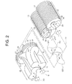
- a screw pump 11 has a rotor housing 12 in which a first screw rotor 13 and a second screw rotor 14 are provided rotatably.
- the shaft 15 of the first screw rotor 13 and the shaft 16 of the second screw rotor 14 extend into a motor housing 17 of the screw pump 11 where an electric motor 18 is accommodated.
- Driving force generated by the electric motor 18 is transmitted through its output shaft 181 and the coupling 19 to the shaft 15, thus rotating the shaft 15.
- the rotating motion of the shaft 15 is transmitted to the other shaft 16 through a pair of gears 20 and 21 engaged with each other, so that the shaft 16 is rotated in the direction opposite to the shaft 15.
- the first screw rotor 13 is rotated in the direction indicated by arrow W
- the second screw rotor 14 is rotated in the direction indicated by arrow Z opposite to the arrow direction W.
- the first screw rotor 13 includes a double-thread portion 26 (multiple-thread portion) and a single-thread portion 29.
- the double-thread portion 26 has two helical teeth 22, 23 and two helical grooves 24, 25.
- the single-thread portion 29 has one helical tooth 27 and one helical groove 28.
- the second screw rotor 14 includes a double-thread portion 34 (multiple-thread portion) and a single-thread portion 37.
- the double-thread portion 34 has two helical teeth 30, 31 and two helical grooves 32, 33.
- the single-thread portion 37 has one helical tooth 35 and one helical groove 36.
- the helical teeth 22, 23 of the double-thread portion 26 of the first screw rotor 13 are engaged with the helical teeth 30, 31 of the double-thread portion 34 of the second screw rotor 14 with the helical teeth 22, 23 inserted in the helical grooves 32, 33 of the double-thread portion 34 of the second screw rotor 14 and the helical teeth 30, 31 inserted in the helical grooves 24, 25 of the double-thread portion 26 of the first screw rotor 13.
- the helical tooth 27 of the single-thread portion 29 of the first screw rotor 13 is engaged with the helical tooth 35 of the single-thread portion 37 of the second screw rotor 14 with the helical tooth 27 inserted in the helical groove 36 of the single-thread portion 37 of the second screw rotor 14 and the helical tooth 35 inserted in the helical groove 28 of the single-thread portion 29 of the first screw rotor 13.
- the double-thread portion 26 is formed continuously with the single-thread portion 29 through a boundary plane 38.
- the double-thread portion 26 is located on the suction side of the screw pump 11, and the single-thread portion 29 is located on the discharge side of the screw pump 11.
- the double-thread portion 34 is formed continuously with the single-thread portion 37 through a boundary plane 39.
- the double-thread portion 34 is located on the suction side of the screw pump 11, and the single-thread portion 37 is located on the discharge side of the screw pump 11.
- the boundary planes 38, 39 lie in the same imaginary plane that is perpendicular to the rotation axes 151, 161 of the first and second screw rotors 13, 14.
- the rotor housing 12 is formed by an end wall 122 and a peripheral wall 123.
- the rotor housing 12 has on one end thereof an inlet 40 formed through the end wall 122 so as to communicate with the suction chamber 121 defined in the rotor housing 12.
- a cover plate 10 is provided in the suction chamber 121 so as to cover part of the end surfaces of the first and second screw rotors 13, 14.
- the rotor housing 12 has on the other end thereof an outlet 41 formed through the peripheral wall 123 so as to communicate with the interior space of the rotor housing 12.
- Fluid is introduced through the inlet 40 into the suction chamber 121 with the rotation of the first and second screw rotors 13, 14.
- the fluid is introduced into the transfer space at a given timing due to the presence of the cover plate 10, transferred in the helical groove toward the outlet 41, then discharged out of the screw pump 11 through the outlet 41.
- Fig. 3 shows a tooth profile G21 of the double-thread portion 26 of the first screw rotor 13 and a tooth profile G22 of the double-thread portion 34 of the second screw rotor 14.
- Fig. 4 shows a tooth profile G11 of the single-thread portion 29 of the first screw rotor 13 and a tooth profile G12 of the single-thread portion 37 of the second screw rotor 14.
- the tooth profile of the first screw rotor 13 is the profile of the first screw rotor 13 in an imaginary plane that is perpendicular to the rotation axis 151
- the tooth profile of the second screw rotor 14 is the profile of the second screw rotor 14 in an imaginary plane that is perpendicular to the rotation axis 161.
- the thread direction of the first screw rotor 13 (indicated by arrow ⁇ in Figs. 3 and 4 ) is opposite to the rotation direction W of the first screw rotor 13.
- the thread direction of the second screw rotor 14 (indicated by arrow ⁇ in Figs. 3 and 4 ) is opposite to the rotation direction Z of the second screw rotor 14.
- the thread direction ⁇ of the first screw rotor 13 is opposite to the thread direction ⁇ of the second screw rotor 14.
- the symbol P1 denotes the point on the central axis of the shaft 15 (i.e., the rotation axis 151 of the first screw rotor 13), and the symbol P2 denotes the point on the central axis of the shaft 16 (i.e., the rotation axis 161 of the second screw rotor 14).
- These points P1, P2, that is, the rotation centers of the first and second screw rotors 13, 14, will be hereinafter referred to as the central points P1, P2.
- the symbol L denotes the distance between the central points P1 and P2 (i.e., the distance between the central axes of the shafts 15 and 16).
- the tooth profile G11 of the single-thread portion 29 of the first screw rotor 13 includes a tooth top portion A1B1 and a tooth bottom portion C1D1.
- the tooth top portion A1B1 extends circularly from point A1 to point B1 about the central point P1.
- the tooth bottom portion C1D1 extends circularly from point C1 to point D1 about the central point P1.
- the radius of the tooth bottom portion C1D1 is smaller the radius of the tooth top portion A1B1.
- the tooth profile G11 further includes a first curved portion A1C1 and a second curved portion B1D1.
- the first curved portion A1C1 connects one end A1 of the tooth top portion A1B1 to one end C1 of the tooth bottom portion C1D1.
- the second curved portion B1D1 connects the other end B1 of the tooth top portion A1B1 to the other end D1 of the tooth bottom portion C1D1.
- the first curved portion A1C1 is formed by a trochoidal curve and hereinafter referred to also as first trochoidal curve A1C1.
- the tooth profile G12 of the single-thread portion 37 of the second screw rotor 14 includes a tooth top portion A2B2 and a tooth bottom portion C2D2.
- the tooth top portion A2B2 extends circularly from point A2 to point B2 about the central point P2.
- the tooth bottom portion C2D2 extends circularly from point C2 to point D2 about the central point P2.
- the radius of the tooth bottom portion C2D2 is smaller the radius of the tooth top portion A2B2.
- the tooth profile G12 further includes a first curved portion A2C2 and a second curved portion B2D2.
- the first curved portion A2C2 connects one end A2 of the tooth top portion A2B2 to one end C2 of the tooth bottom portion C2D2.
- the second curved portion B2D2 connects the other end B2 of the tooth top portion A2B2 to the other end D2 of the tooth bottom portion C2D2.
- the first curved portion A2C2 is formed by a trochoidal curve and hereinafter referred to also as first trochoidal curve A2C2.
- the one end A1 of the tooth top portion A1B1 and the one end A2 of the tooth top portion A2B2 lie on the imaginary line M passing through the central points P1 and P2.
- the first trochoidal curve A1C1 of the first screw rotor 13 is created by the one end A2 of the tooth top portion A2B2 of the second screw rotor 14.
- the first trochoidal curve A2C2 of the second screw rotor 14 is created by the one end A1 of the tooth top portion A1B1 of the first screw rotor 13.
- the second curved portion B2D2 of the second screw rotor 14 is formed by an involute curve B2E2 connecting to the other end B2 of the tooth top portion A2B2 and a second trochoidal curve E2D2.
- the involute curve B2E2 is obtained from a base circle the center of which is the central point P2.
- the second trochoidal curve E2D2 is created by the other end B1 of the tooth top portion A1B1 of the first screw rotor 13.
- the second curved portion B1D1 of the first screw rotor 13 is formed by an involute curve B1E1 connecting to the other end B1 of the tooth top portion A1B1 and a second trochoidal curve E1D1.
- the involute curve B1E1 is obtained from a base circle the center of which is the central point P1 and the radius of which is smaller than half of the distance L (L/2).
- the second trochoidal curve E1D1 is created by the other end B2 of the tooth top portion A2B2 of the second screw rotor 14.
- the tooth profile G12 of the single-thread portion 37 of the second screw rotor 14 is identical to the tooth profile G11 of the single-thread portion 29 of the first screw rotor 13.
- the angle ⁇ 1 of the tooth top portion A1B1 of the first screw rotor 13 about the central point P1 is smaller than 180 degree.
- the angle ⁇ 2 of the tooth bottom portion C1D1 about the central point P1 is also smaller than 180 degree and equal to the angle ⁇ 1.
- the angle of the tooth top portion A2B2 of the second screw rotor 14 about the central point P2 is ⁇ 1
- the angle of the tooth bottom portion C2D2 about the central point P2 is ⁇ 2 that is equal to ⁇ 1.
- reference numerals 13 and 14 in Figs. 6 through 8 denotes the side of the first screw rotor 13 and the side of the second screw rotor 14, respectively.
- the distance between the central points P1 and P2 i.e., distance L
- an outer circle C11 with the radius R1 that is larger than r and an inner circle C21 with the radius R2 that is smaller than r are determined.
- the distance L is the sum of the radius R1 and the radius R2.
- the pitch circle C31 is associated with the first screw rotor 13
- the pitch circle C32 is associated with the second screw rotor 14.
- an involute curve I1 passing through the point F is determined based on a base circle Co1 the center of which is the central point P1 and the radius of which is smaller than that of the pitch circle C31.
- the intersection of the involute curve I1 with the outer circle C11 on the first screw rotor 13 is the point B1 that corresponds to the aforementioned other end B1 of the tooth top portion A1B1 of the first screw rotor 13.
- an involute curve I2 passing through the point F is determined based on a base circle Co2 the center of which is the central point P2 and the radius of which is smaller than that of the pitch circle C32.
- the intersection of the involute curve I2 with the outer circle C12 on the second screw rotor 14 is the point B2 that corresponds to the aforementioned other end B2 of the tooth top portion A2B2 of the second screw rotor 14.
- Both of the base circles Co1, Co2 have the radius Ro that is smaller than the radius r of the pitch circles C31, C32.
- the curve J1 is the trajectory of the point B2 on the outer circle C12 that is described when the first and second screw rotors 13, 14 are rotated.
- the curve J1 is a trochoidal curve created by rolling the second screw rotor 14 around the first screw rotor 13 with the pitch circle C32 kept in contact with the pitch circle C31.
- the intersection D1 of the trochoidal curve J1 with the inner circle C21 corresponds to the aforementioned other end D1 of the tooth bottom portion C1 D1 of the first screw rotor 13.
- the trochoidal curve J1 is connected to the involute curve I1 at point E1.
- the involute curve B1E1 in the first screw rotor 13 is formed by the involute curve I1 extending from the point B1 to the point E1
- the second trochoidal curve E1D1 in the first screw rotor 13 is formed by the trochoidal curve J1 extending from the point E1 to the point D1.
- the tangent to the second trochoidal curve E1D1 coincides with the tangent to the involute curve B1E1 at the connection point therebetween.
- a curve J2 is determined.
- the curve J2 is the trajectory of the point B1 on the outer circle C11 that is described when the first and second screw rotors 13, 14 are rotated.
- the curve J2 is a trochoidal curve created by rolling the first screw rotor 13 around the second screw rotor 14 with the pitch circle C31 kept in contact with the pitch circle C32.
- the intersection D2 of the trochoidal curve J2 with the inner circle C22 corresponds to the aforementioned other end D2 of the tooth bottom portion C2D2 of the second screw rotor 14.
- the trochoidal curve J2 is connected to the involute curve I2 at point E2.
- the involute curve B2E2 in the second screw rotor 14 is formed by the involute curve I2 extending from the point B2 to the point E2, and the second trochoidal curve E2D2 in the second screw rotor 14 is formed by the trochoidal curve J2 extending from the point E2 to the point D2.
- the tangent to the second trochoidal curve E2D2 coincides with the tangent to the involute curve B2E2 at the connection point therebetween.
- a point A1 and a curve K1 are determined.
- the point A1 lies on the line M passing through the central points P1, P2 and also on the outer circle C11 on the first screw rotor 13 side.
- the curve K1 is the trajectory of the point A2 on the outer circle C12 that is described when the first and second screw rotors 13, 14 are rotated.
- the curve K1 is a trochoidal curve created by rolling the second screw rotor 14 around the first screw rotor 13 with the pitch circle C32 kept in contact with the pitch circle C31.
- the point A1 corresponds to the aforementioned one end A1 of the tooth top portion A1B1 of the first screw rotor 13.
- the first trochoidal curve A1C1 in the first screw rotor 13 is formed by the trochoidal curve K1 extending from the point A1 to the point C1 that is the intersection of the trochoidal curve K1 with the inner circle C21.
- a point A2 and a curve K2 are determined.
- the point A2 lies on the line M passing through the central points P1, P2 and also on the outer circle C12 on the second screw rotor 14 side.
- the curve K2 is the trajectory of the point A1 on the outer circle C11 that is described when the first and second screw rotors 13, 14 are rotated.
- the curve K2 is a trochoidal curve created by rolling the first screw rotor 13 around the second screw rotor 14 with the pitch circle C31 kept in contact with the pitch circle C32.
- the point A2 corresponds to the aforementioned one end A2 of the tooth top portion A2B2 of the second screw rotor 14.
- the first trochoidal curve A2C2 in the second screw rotor 14 is formed by the trochoidal curve K2 extending from the point A2 to the point C2 that is the intersection of the trochoidal curve K2 with the inner circle C22.
- the tooth top portion A1B1 of the first screw rotor 13 is formed by the arc of the outer circle C11 extending from the point A1 on the first trochoidal curve A1C1 to the point B1 on the involute curve B1E1.
- the tooth bottom portion C1D1 of the first screw rotor 13 is formed by the arc of the inner circle C21 extending from the point C1 on the first trochoidal curve A1C1 to the point D1 on the second trochoidal curve E1D1.
- the tooth top portion A2B2 and the tooth bottom portion C2D2 of the second screw rotor 14 are formed in substantially the same manner as in the case of the first screw rotor 13.
- the point A2 of the second screw rotor 14 is moved along the first trochoidal curve A1C1 of the first screw rotor 13 with the rotation of the first and second screw rotors 13, 14. Then, the point A1 of the first screw rotor 13 is moved along the first trochoidal curve A2C2 of the second screw rotor 14.
- the point B1 of the first screw rotor 13 is moved along the second trochoidal curve E2D2 of the second screw rotor 14 with the rotation of the first and second screw rotors 13, 14. Then, the involute curve B1E1 of the first screw rotor 13 rolls on the involute curve B2E2 of the second screw rotor 14 while being kept in contact therewith. Then, the point B2 of the second screw rotor 14 is moved along the second trochoidal curve E1D1 of the first screw rotor 13.
- the tooth profile G21 of the double-threaded portion 26 of the first screw rotor 13 includes a tooth top portion 42A, a tooth bottom portion 43A, a tooth bottom portion 44A, a tooth top portion 45A, a third curved portion 46A formed by a trochoidal curve, a fourth curved portion 47A, and curved portions 48A, 49A.
- the third curved portion 46A connects one end 422A of the tooth top portion 42A (i.e., one end 461A of the third curved portion 46A) to one end of the tooth bottom portion 43A.
- the other end 421A of the tooth top portion 42A is connected to the fourth curved portion 47A.
- the fourth curved portion 47A and the curved portions 48A, 49A are formed by an involute curve and a trochoidal curve.
- the tooth top portion 42A, the tooth bottom portion 43A, the tooth bottom portion 44A and the tooth top portion 45A are the arcs of the circles the centers of which are the central point P1.
- the tooth profile G22 of the double-threaded portion 34 of the second screw rotor 14 includes a tooth top portion 428, a tooth bottom portion 43B, a tooth bottom portion 44B, a tooth top portion 45B, a third curved portion 46B formed by a trochoidal curve, a fourth curved portion 47B, and curved portions 48B, 49B.
- the third curved portion 46B connects one end 422B of the tooth top portion 42B (i.e., one end 461B of the third curved portion 46B) to one end of the tooth bottom portion 43B.
- the other end 421B of the tooth top portion 42B is connected to the fourth curved portion 47B.
- the fourth curved portion 47B and the curved portions 48B, 49B are formed by an involute curve and a trochoidal curve.
- the tooth top portion 42B, the tooth bottom portion 43B, the tooth bottom portion 44B and the tooth top portion 45B are the arcs of the circles the centers of which are the central point P2.
- the tooth profile G22 of the double-thread portion 34 of the second screw rotor 14 is identical to the tooth profile G21 of the double-thread portion 26 of the first screw rotor 13.
- the radii of the tooth top portions 42A, 42B, 45A, 458 in the tooth profiles G21, G22 and of the tooth top portions A1B1, A2B2 in the tooth profiles G11, G12 of the single-thread portions 29, 37 are substantially equal.
- the radii of the tooth bottom portions 43A, 43B, 44A, 44B in the tooth profiles G21, G22 and of the tooth bottom portions C1D1, C2D2 in the tooth profiles G11, G12 of the single-thread portions 29, 37 are substantially equal.
- the third curved portions 46A, 46B formed by a trochoidal curve in the tooth profiles G21, G22 are created in the same manner as in the case of the first curved portions A1C1, A2C2 formed by a trochoidal curve in the tooth profiles G11, G12.
- the profile of the third curved portions 46A, 46B is identical to the profile of the first curved portions A1C1, A2C2 formed by a trochoidal curve in the tooth profiles G11, G12.
- the fourth curved portions 47A, 478 and the curved portions 48A, 48B, 49A, 49B each formed by an involute curve and a trochoidal curve are created in the same manner as in the case of the second curved portions B1D1, B2D2 in the tooth profiles G11, G12 of the single-thread portion 29, 37.
- the one end 461B of the third curved portion 46B sweeps along the third curved portion 46A
- the one end 461A of the third curved portion 46A sweeps along the third curved portion 46B.
- the fourth curved portion 47A faces the fourth curved portion 47B
- the curved portion 48A faces the curved portion 48B
- the curved portion 49A faces the curved portion 49B.
- the tooth profiles G11, G12 of the single-thread portions 29, 37 and the tooth profiles G21, G22 of the double-thread portions 26, 34 thus created are located so that the tooth profile G21 is connected to the tooth profile G11 through the boundary plane 38 and the tooth profile G22 is connected to the tooth profile G12 through the boundary plane 39.
- Fig. 9A schematically shows the tooth profiles G21, G22 of the double-thread portions 26, 34 and the tooth profiles G11, G12 of the single-thread portions 29, 37 in the boundary planes 38, 39.
- the symbol ⁇ 1 ( ⁇ 0) denotes the difference of angular position about the central point P1 in the boundary plane 38 between the third curved portion 46A (trochoidal curve) of the tooth profile G21 of the double-thread portion 26 and the first curved portion A1C1 (trochoidal curve) of the tooth profile G11 of the single-thread portion 29.
- the difference of angular position ⁇ 1, that is, the angular difference ⁇ 1 is zero.
- ⁇ 2 ( ⁇ 0) denotes the difference of angular position about the central point P2 in the boundary plane 39 between the third curved portion 46B (trochoidal curve) of the tooth profile G22 of the double-thread portion 34 and the first curved portion A2C2 (trochoidal curve) of the tooth profile G12 of the single-thread portion 37.
- the difference of angular position ⁇ 2, that is, the angular difference ⁇ 2 is zero.
- ⁇ 1 is equal to ⁇ 2 and, therefore, the angular differences ⁇ 1, ⁇ 2 will be hereinafter indicated by the symbol ⁇ o.
- the symbol ⁇ 1 denotes the angle between the line L11 extending from the one end 422A of the tooth top portion 42A to the central point P1 and the line L12 extending from the other end 421 A of the tooth top portion 42A to the central point P1.
- the symbol ⁇ 1 denotes the angle between the lines L11 and L12 passing through the respective ends 422A, 421A of the tooth top portion 42A as an arc about the central point P1 in the boundary plane 38.
- the symbol ⁇ 2 denotes the angle between the line L21 extending from the one end 4228 of the tooth top portion 42B to the central point P2 and the line L22 extending from the other end 421B of the tooth top portion 428 to the central point P2.
- the symbol ⁇ 2 denotes the angle between the lines L21, L22 passing through the respective ends 422B, 421B of the tooth top portion 42B as an arc about the central point P2 in the boundary plane 39.
- ⁇ 1 is equal to ⁇ 2 and, therefore, the angles ⁇ 1, ⁇ 2 will be hereinafter indicated by the symbol ⁇ o.
- Fig. 9B shows the state where the tooth profile G11 have been shifted from the position of Fig. 9A by being rotated by ⁇ o ( ⁇ ⁇ o) in the direction opposite to the rotation direction W (i.e. thread direction ⁇ ) and also shows the state where the tooth profile G12 have been shifted from the position of Fig. 9A by being rotated by ⁇ o ( ⁇ ⁇ o) in the direction opposite to the rotation direction Z (i.e. thread direction ⁇ ).
- Fig. 9C shows the state where the tooth profile G11 have been shifted from the position of Fig. 9A by being rotated by ⁇ o ( ⁇ ⁇ o) in the rotation direction W (i.e. the direction opposite to the thread direction ⁇ ) and also shows the state where the tooth profile G12 have been shifted from the position of Fig. 9A by being rotated by ⁇ o ( ⁇ ⁇ o) in the rotation direction Z (i.e. the direction opposite to the thread direction ⁇ ).
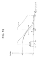
- Fig. 10 the horizontal axis represents the angular position of the first and second screw rotors 13, 14, and the vertical axis represents the fluid volume.
- Figs. 9A , 9B, 9C show the state where the angular position of the first and second screw rotors 13, 14 is 0 degree in Fig. 10 .
- the volume V2 of the helical grooves of the single-thread portions 29, 37 located downstream of and adjacent to the boundary planes 38, 39 is changed as indicated by the curve Q in Fig. 10 with the rotation of the first and second screw rotors 13, 14.
- the volume V2 indicated by the curve Q increases gradually and then converges to a predetermined value that is the volume of the helical grooves of the single-thread portions 29, 37 away from the boundary planes 38, 39 (hereinafter referred to as Vq).
- the change of the volume V2 with the rotation of the first and second screw rotors 13, 14 is delayed by ⁇ o relative to the curve Q in Fig. 10 . That is, the volume V2 is changed in accordance with the curve that is shifted by ⁇ o rightward in Fig. 10 from the position of the curve Q.
- the fluid transfer volume (V1+V2), which is the sum of the volumes V1 and V2, is changed as indicated by the curve HQ in Fig. 10 .
- the helical groove of the single-thread portion 29 located downstream of and adjacent to the boundary plane 38 is not connected to the helical groove of the double-thread portion 26 within the range of - ⁇ o to 0 degree.
- the fluid transfer volume is increased rapidly by the volume of the helical groove of the single-thread portion 29 connected to the helical groove of the double-thread portion 26.
- Fig. 11A shows the state where there exists a gap g1 between the fourth curved portion 47A of the tooth profile G21 of the double-thread portion 26 and the first curved portion A1C1 of the tooth profile G11 of the single-thread portion 29 in the boundary plane 38.
- two different fluid transfer spaces adjacent to the third curved portion 46A which is formed by the helical groove 24 of the double-thread portion 26 adjacent to the boundary plane 38, are connected with each other through the helical groove 28 of the single-thread portion 29 adjacent to the boundary plane 38. That is, two different fluid transfer spaces located upstream and downstream of the third curved portion 46A are connected.
- Fig. 11B shows the state where there exists a gap g2 between the fourth curved portion 47B of the tooth profile G22 of the double-thread portion 34 and the first curved portion A2C2 of the tooth profile G12 of the single-thread portion 37 in the boundary plane 39.
- two different fluid transfer spaces adjacent to the third curved portion 46B which is formed by the helical groove 32 of the double-thread portion 34 adjacent to the boundary plane 39, are connected with each other through the helical groove 36 of the single-thread portion 37 adjacent to the boundary plane 39. That is, two different fluid transfer spaces located upstream and downstream of the third curved portion 46B are connected.
- gaps g1, g2 causes rapid increase and decrease in the fluid transfer volume, as shown by the curve S in Fig. 10 .
- the gaps g1, g2 may be generated depending on the combination of the profiles of the fourth curved portions 47A, 478 and the number of threads in the multiple-thread portion even when the condition ⁇ o ⁇ ⁇ o is satisfied. In such a case, the combination is limited to the one that does not cause such g1, g2.
- the first and second screw rotors 13, 14 according to the first embodiment offer the following advantages.
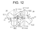
- the present invention is applicable to a screw rotor having single-thread portion with tooth profiles such as G11, G12 and multiple-thread portions, or triple-thread portions with tooth profiles G31, G32 as shown in Fig. 12 .
- the tooth profiles G31, G32 are substantially identical to those disclosed in Japanese Examined Patent Application Publication No. 63-59031 .
- the tooth profiles G31, G32 include third curved portions 46A, 46B formed by a trochoidal curve.
- the tooth profiles G31, G32 of the multiple-thread portions and the tooth profiles G11, G12 of the single-thread portions satisfy the conditions (1) or (2) described above.
- the second curved portions B1D1, B2D2, the fourth curved portions 47A, 47B and the curved portions 48A, 48B, 49A, 49B may be formed by a curve based on a circular arc other than involute curve and trochoidal curve.
- the present invention is applicable to a screw rotor including a single-thread portion and a multiple-thread portion the number of threads of which is four or more.
Landscapes
- Engineering & Computer Science (AREA)
- Mechanical Engineering (AREA)
- General Engineering & Computer Science (AREA)
- Rotary Pumps (AREA)
- Applications Or Details Of Rotary Compressors (AREA)
- Details And Applications Of Rotary Liquid Pumps (AREA)
Applications Claiming Priority (1)
| Application Number | Priority Date | Filing Date | Title |
|---|---|---|---|
| JP2009171114A JP5353521B2 (ja) | 2009-07-22 | 2009-07-22 | スクリューロータ |
Publications (3)
| Publication Number | Publication Date |
|---|---|
| EP2295801A2 true EP2295801A2 (fr) | 2011-03-16 |
| EP2295801A3 EP2295801A3 (fr) | 2015-06-24 |
| EP2295801B1 EP2295801B1 (fr) | 2016-11-09 |
Family
ID=42937128
Family Applications (1)
| Application Number | Title | Priority Date | Filing Date |
|---|---|---|---|
| EP10170100.1A Not-in-force EP2295801B1 (fr) | 2009-07-22 | 2010-07-20 | Rotor pour une pompe à vis |
Country Status (6)
| Country | Link |
|---|---|
| US (1) | US8556607B2 (fr) |
| EP (1) | EP2295801B1 (fr) |
| JP (1) | JP5353521B2 (fr) |
| KR (1) | KR101132894B1 (fr) |
| CN (1) | CN101963153B (fr) |
| TW (1) | TWI408283B (fr) |
Cited By (1)
| Publication number | Priority date | Publication date | Assignee | Title |
|---|---|---|---|---|
| DE102013102030B3 (de) * | 2013-03-01 | 2014-07-03 | Netzsch Pumpen & Systeme Gmbh | Schraubenspindelpumpe |
Families Citing this family (19)
| Publication number | Priority date | Publication date | Assignee | Title |
|---|---|---|---|---|
| CN102094811B (zh) * | 2011-02-15 | 2013-09-11 | 李锦上 | 非直线型产形面二次包络型线单螺杆啮合副 |
| CN102352840B (zh) * | 2011-09-29 | 2013-08-28 | 陕西丰赜机电科技有限公司 | 螺杆转子端面廓形副及其构造方法 |
| EP3467314B1 (fr) * | 2012-06-28 | 2021-08-04 | Sterling Industry Consult GmbH | Pompe à vis |
| WO2014167503A1 (fr) * | 2013-04-09 | 2014-10-16 | Indian Institute Of Technology Madras | Appareil pour mesurer des paramètres rhéologiques, et ses procédés de fonctionnement |
| US9863860B2 (en) | 2013-08-26 | 2018-01-09 | Indian Institute Of Technology Madras | Methods and apparatus for measuring rheological properties of multi-phase fluids |
| DE102014000911B4 (de) * | 2014-01-28 | 2016-01-28 | Klaus Union Gmbh & Co. Kg | Förderschraube als Läufer oder Gegenläufer eines Förderschraubenpaares einer Schraubenpumpe |
| CN105156323B (zh) * | 2015-09-10 | 2018-11-13 | 中国科学院等离子体物理研究所 | 一种冷压机转子 |
| DE102015218679B4 (de) * | 2015-09-29 | 2019-08-29 | Skf Lubrication Systems Germany Gmbh | Schraubenspindelpumpe |
| EP3499041B1 (fr) * | 2017-12-15 | 2020-07-01 | Pfeiffer Vacuum Gmbh | Pompe à vide à vis |
| CN108223359B (zh) * | 2017-12-19 | 2019-12-24 | 江南大学 | 一种调节啮合线段修改转子型线性能的方法 |
| US10883496B2 (en) | 2017-12-19 | 2021-01-05 | Jiangnan University | Method for modifying performance of rotor profile by adjusting meshing line segments |
| CN108180140B (zh) * | 2017-12-20 | 2023-10-27 | 杭州电子科技大学 | 一种全密封型双螺杆泵 |
| CA3128596A1 (fr) * | 2019-03-14 | 2020-09-17 | Ateliers Busch S.A. | Pompe seche pour gaz et jeu de plusieurs pompes seches pour gaz |
| DE102019132653A1 (de) * | 2019-12-02 | 2021-06-02 | Leistritz Pumpen Gmbh | Schraubenspindelpumpe |
| ES2914979T3 (es) | 2019-12-19 | 2022-06-20 | Contelec Ag | Bomba de pistón axial |
| CN111457070A (zh) * | 2020-04-13 | 2020-07-28 | 中国船舶重工集团公司第七0四研究所 | 具有摆线螺纹牙廓的行星滚柱丝杠 |
| JP7616859B2 (ja) * | 2020-10-23 | 2025-01-17 | 株式会社日立産機システム | スクリュー圧縮機及びスクリューロータ |
| TWI795125B (zh) * | 2021-03-29 | 2023-03-01 | 超詮工業股份有限公司 | 適用高壓液體之粉末冶金擺線轉子泵 |
| CN114109824B (zh) * | 2021-11-25 | 2023-08-15 | 江南大学 | 一种双螺杆转子型线综合性能判断及优化设计方法 |
Citations (3)
| Publication number | Priority date | Publication date | Assignee | Title |
|---|---|---|---|---|
| JPS6359031B2 (fr) | 1980-10-17 | 1988-11-17 | ||
| JPH03111690A (ja) | 1989-09-22 | 1991-05-13 | Tokuda Seisakusho Ltd | 真空ポンプ |
| JP2008038861A (ja) | 2006-08-10 | 2008-02-21 | Toyota Industries Corp | スクリューポンプ |
Family Cites Families (11)
| Publication number | Priority date | Publication date | Assignee | Title |
|---|---|---|---|---|
| US1698802A (en) * | 1924-04-07 | 1929-01-15 | Montelius Carl Oscar Josef | Device for transferring energy to or from alpha fluid |
| JPS6359031A (ja) | 1986-08-27 | 1988-03-14 | Stanley Electric Co Ltd | 光受信機 |
| JP3111690B2 (ja) | 1992-10-01 | 2000-11-27 | トヨタ自動車株式会社 | 圧電積層体の製造方法 |
| JP2904719B2 (ja) * | 1995-04-05 | 1999-06-14 | 株式会社荏原製作所 | スクリューロータ及びその歯形の軸直角断面形状を決定する方法並びにスクリュー機械 |
| EP1026399A1 (fr) * | 1999-02-08 | 2000-08-09 | Ateliers Busch S.A. | Vis transporteuses jumelées |
| CN1880769A (zh) * | 2005-06-13 | 2006-12-20 | 上海汉钟机械有限公司 | 螺旋式真空泵的螺旋转子齿形 |
| CN100360810C (zh) * | 2005-09-30 | 2008-01-09 | 浙江大学 | 一种大流量高压双螺杆泵的螺杆齿形 |
| TWI438342B (zh) * | 2006-07-28 | 2014-05-21 | Lot Vacuum Co Ltd | 具有魯式與螺旋轉子之複合型乾式真空幫浦 |
| KR100855187B1 (ko) * | 2006-11-16 | 2008-09-01 | (주)엘오티베큠 | 루츠 로터와 스크루 로터 복합건식진공펌프 |
| KR100976112B1 (ko) * | 2006-09-05 | 2010-08-16 | 가부시키가이샤 도요다 지도숏키 | 스크루 펌프 및 스크루 로터 |
| KR100747225B1 (ko) | 2006-11-13 | 2007-08-07 | 주식회사 브이피에스 | 계단형 압축식 이종 무단 리이드 진공펌프용 스크류 |
-
2009
- 2009-07-22 JP JP2009171114A patent/JP5353521B2/ja active Active
-
2010
- 2010-07-16 US US12/837,575 patent/US8556607B2/en not_active Expired - Fee Related
- 2010-07-20 TW TW099123734A patent/TWI408283B/zh not_active IP Right Cessation
- 2010-07-20 EP EP10170100.1A patent/EP2295801B1/fr not_active Not-in-force
- 2010-07-21 KR KR1020100070360A patent/KR101132894B1/ko not_active Expired - Fee Related
- 2010-07-21 CN CN201010277965.7A patent/CN101963153B/zh not_active Expired - Fee Related
Patent Citations (3)
| Publication number | Priority date | Publication date | Assignee | Title |
|---|---|---|---|---|
| JPS6359031B2 (fr) | 1980-10-17 | 1988-11-17 | ||
| JPH03111690A (ja) | 1989-09-22 | 1991-05-13 | Tokuda Seisakusho Ltd | 真空ポンプ |
| JP2008038861A (ja) | 2006-08-10 | 2008-02-21 | Toyota Industries Corp | スクリューポンプ |
Cited By (1)
| Publication number | Priority date | Publication date | Assignee | Title |
|---|---|---|---|---|
| DE102013102030B3 (de) * | 2013-03-01 | 2014-07-03 | Netzsch Pumpen & Systeme Gmbh | Schraubenspindelpumpe |
Also Published As
| Publication number | Publication date |
|---|---|
| CN101963153B (zh) | 2013-09-11 |
| EP2295801B1 (fr) | 2016-11-09 |
| KR101132894B1 (ko) | 2012-04-03 |
| CN101963153A (zh) | 2011-02-02 |
| US20110020162A1 (en) | 2011-01-27 |
| EP2295801A3 (fr) | 2015-06-24 |
| JP2011026981A (ja) | 2011-02-10 |
| TW201109527A (en) | 2011-03-16 |
| KR20110009629A (ko) | 2011-01-28 |
| US8556607B2 (en) | 2013-10-15 |
| TWI408283B (zh) | 2013-09-11 |
| JP5353521B2 (ja) | 2013-11-27 |
Similar Documents
| Publication | Publication Date | Title |
|---|---|---|
| EP2295801B1 (fr) | Rotor pour une pompe à vis | |
| CN1242170C (zh) | 环形齿轮机械的间隙 | |
| EP2060789A1 (fr) | Pompe à vis et rotor en forme de vis | |
| EP0736667A2 (fr) | Rotor à vis et procédé de génération du profil de ses dents | |
| US8360762B2 (en) | Oil pump rotor | |
| US20080193301A1 (en) | Composite fluid machine | |
| US10400769B2 (en) | Rotor pair for a compression block of a screw machine | |
| US20080038137A1 (en) | Screw pump | |
| TWI906447B (zh) | 用於三螺桿泵的螺桿組合件及包括該組合件的螺桿泵 | |
| CA2362075A1 (fr) | Vis sans fin jumelles destinees a etre installees dans des machines de deplacement, en particulier des pompes | |
| WO2022179746A1 (fr) | Ensemble vis pour pompe à triple vis et pompe à triple vis comprenant ledit ensemble | |
| US20080193315A1 (en) | Roots-type fluid machine | |
| US6257855B1 (en) | Screw fluid machine | |
| US12031536B2 (en) | Screw compressor and screw rotor | |
| JP2009085213A (ja) | 内接ギヤポンプ | |
| US20080193316A1 (en) | Roots pump | |
| CN113544384B (zh) | 干式气体泵和多个干式气体泵的组 | |
| CN113236561A (zh) | 一种变螺距的同向啮合双螺杆压缩机转子及压缩机 | |
| US8075288B2 (en) | Screw pump and pumping arrangement | |
| EP1421282B1 (fr) | Pompe volumetrique a butee de contrepression | |
| Giuffrida | A geometric study of different curves for the rotor profiles of a twin-screw compressor | |
| GB2114667A (en) | Rotary positive-displacement pumps | |
| EP3161261A1 (fr) | Paire de rotors coopérants en forme de vis |
Legal Events
| Date | Code | Title | Description |
|---|---|---|---|
| PUAI | Public reference made under article 153(3) epc to a published international application that has entered the european phase |
Free format text: ORIGINAL CODE: 0009012 |
|
| 17P | Request for examination filed |
Effective date: 20100720 |
|
| AK | Designated contracting states |
Kind code of ref document: A2 Designated state(s): AL AT BE BG CH CY CZ DE DK EE ES FI FR GB GR HR HU IE IS IT LI LT LU LV MC MK MT NL NO PL PT RO SE SI SK SM TR |
|
| AX | Request for extension of the european patent |
Extension state: BA ME RS |
|
| PUAL | Search report despatched |
Free format text: ORIGINAL CODE: 0009013 |
|
| AK | Designated contracting states |
Kind code of ref document: A3 Designated state(s): AL AT BE BG CH CY CZ DE DK EE ES FI FR GB GR HR HU IE IS IT LI LT LU LV MC MK MT NL NO PL PT RO SE SI SK SM TR |
|
| AX | Request for extension of the european patent |
Extension state: BA ME RS |
|
| RIC1 | Information provided on ipc code assigned before grant |
Ipc: F04C 2/12 20060101ALI20150521BHEP Ipc: F04C 2/16 20060101AFI20150521BHEP |
|
| GRAP | Despatch of communication of intention to grant a patent |
Free format text: ORIGINAL CODE: EPIDOSNIGR1 |
|
| RIC1 | Information provided on ipc code assigned before grant |
Ipc: F04C 14/02 20060101ALI20160413BHEP Ipc: F04C 2/12 20060101ALI20160413BHEP Ipc: F04C 2/16 20060101AFI20160413BHEP Ipc: F04C 11/00 20060101ALI20160413BHEP |
|
| INTG | Intention to grant announced |
Effective date: 20160518 |
|
| GRAS | Grant fee paid |
Free format text: ORIGINAL CODE: EPIDOSNIGR3 |
|
| GRAA | (expected) grant |
Free format text: ORIGINAL CODE: 0009210 |
|
| AK | Designated contracting states |
Kind code of ref document: B1 Designated state(s): AL AT BE BG CH CY CZ DE DK EE ES FI FR GB GR HR HU IE IS IT LI LT LU LV MC MK MT NL NO PL PT RO SE SI SK SM TR |
|
| REG | Reference to a national code |
Ref country code: GB Ref legal event code: FG4D |
|
| REG | Reference to a national code |
Ref country code: AT Ref legal event code: REF Ref document number: 844194 Country of ref document: AT Kind code of ref document: T Effective date: 20161115 Ref country code: CH Ref legal event code: EP |
|
| REG | Reference to a national code |
Ref country code: IE Ref legal event code: FG4D |
|
| REG | Reference to a national code |
Ref country code: DE Ref legal event code: R096 Ref document number: 602010037782 Country of ref document: DE |
|
| PG25 | Lapsed in a contracting state [announced via postgrant information from national office to epo] |
Ref country code: LV Free format text: LAPSE BECAUSE OF FAILURE TO SUBMIT A TRANSLATION OF THE DESCRIPTION OR TO PAY THE FEE WITHIN THE PRESCRIBED TIME-LIMIT Effective date: 20161109 |
|
| REG | Reference to a national code |
Ref country code: LT Ref legal event code: MG4D |
|
| REG | Reference to a national code |
Ref country code: NL Ref legal event code: MP Effective date: 20161109 |
|
| REG | Reference to a national code |
Ref country code: AT Ref legal event code: MK05 Ref document number: 844194 Country of ref document: AT Kind code of ref document: T Effective date: 20161109 |
|
| PG25 | Lapsed in a contracting state [announced via postgrant information from national office to epo] |
Ref country code: GR Free format text: LAPSE BECAUSE OF FAILURE TO SUBMIT A TRANSLATION OF THE DESCRIPTION OR TO PAY THE FEE WITHIN THE PRESCRIBED TIME-LIMIT Effective date: 20170210 Ref country code: LT Free format text: LAPSE BECAUSE OF FAILURE TO SUBMIT A TRANSLATION OF THE DESCRIPTION OR TO PAY THE FEE WITHIN THE PRESCRIBED TIME-LIMIT Effective date: 20161109 Ref country code: SE Free format text: LAPSE BECAUSE OF FAILURE TO SUBMIT A TRANSLATION OF THE DESCRIPTION OR TO PAY THE FEE WITHIN THE PRESCRIBED TIME-LIMIT Effective date: 20161109 Ref country code: NL Free format text: LAPSE BECAUSE OF FAILURE TO SUBMIT A TRANSLATION OF THE DESCRIPTION OR TO PAY THE FEE WITHIN THE PRESCRIBED TIME-LIMIT Effective date: 20161109 Ref country code: NO Free format text: LAPSE BECAUSE OF FAILURE TO SUBMIT A TRANSLATION OF THE DESCRIPTION OR TO PAY THE FEE WITHIN THE PRESCRIBED TIME-LIMIT Effective date: 20170209 |
|
| PG25 | Lapsed in a contracting state [announced via postgrant information from national office to epo] |
Ref country code: IS Free format text: LAPSE BECAUSE OF FAILURE TO SUBMIT A TRANSLATION OF THE DESCRIPTION OR TO PAY THE FEE WITHIN THE PRESCRIBED TIME-LIMIT Effective date: 20170309 Ref country code: PT Free format text: LAPSE BECAUSE OF FAILURE TO SUBMIT A TRANSLATION OF THE DESCRIPTION OR TO PAY THE FEE WITHIN THE PRESCRIBED TIME-LIMIT Effective date: 20170309 Ref country code: PL Free format text: LAPSE BECAUSE OF FAILURE TO SUBMIT A TRANSLATION OF THE DESCRIPTION OR TO PAY THE FEE WITHIN THE PRESCRIBED TIME-LIMIT Effective date: 20161109 Ref country code: FI Free format text: LAPSE BECAUSE OF FAILURE TO SUBMIT A TRANSLATION OF THE DESCRIPTION OR TO PAY THE FEE WITHIN THE PRESCRIBED TIME-LIMIT Effective date: 20161109 Ref country code: ES Free format text: LAPSE BECAUSE OF FAILURE TO SUBMIT A TRANSLATION OF THE DESCRIPTION OR TO PAY THE FEE WITHIN THE PRESCRIBED TIME-LIMIT Effective date: 20161109 Ref country code: HR Free format text: LAPSE BECAUSE OF FAILURE TO SUBMIT A TRANSLATION OF THE DESCRIPTION OR TO PAY THE FEE WITHIN THE PRESCRIBED TIME-LIMIT Effective date: 20161109 Ref country code: AT Free format text: LAPSE BECAUSE OF FAILURE TO SUBMIT A TRANSLATION OF THE DESCRIPTION OR TO PAY THE FEE WITHIN THE PRESCRIBED TIME-LIMIT Effective date: 20161109 |
|
| REG | Reference to a national code |
Ref country code: FR Ref legal event code: PLFP Year of fee payment: 8 |
|
| PG25 | Lapsed in a contracting state [announced via postgrant information from national office to epo] |
Ref country code: SK Free format text: LAPSE BECAUSE OF FAILURE TO SUBMIT A TRANSLATION OF THE DESCRIPTION OR TO PAY THE FEE WITHIN THE PRESCRIBED TIME-LIMIT Effective date: 20161109 Ref country code: EE Free format text: LAPSE BECAUSE OF FAILURE TO SUBMIT A TRANSLATION OF THE DESCRIPTION OR TO PAY THE FEE WITHIN THE PRESCRIBED TIME-LIMIT Effective date: 20161109 Ref country code: DK Free format text: LAPSE BECAUSE OF FAILURE TO SUBMIT A TRANSLATION OF THE DESCRIPTION OR TO PAY THE FEE WITHIN THE PRESCRIBED TIME-LIMIT Effective date: 20161109 Ref country code: CZ Free format text: LAPSE BECAUSE OF FAILURE TO SUBMIT A TRANSLATION OF THE DESCRIPTION OR TO PAY THE FEE WITHIN THE PRESCRIBED TIME-LIMIT Effective date: 20161109 Ref country code: RO Free format text: LAPSE BECAUSE OF FAILURE TO SUBMIT A TRANSLATION OF THE DESCRIPTION OR TO PAY THE FEE WITHIN THE PRESCRIBED TIME-LIMIT Effective date: 20161109 |
|
| REG | Reference to a national code |
Ref country code: DE Ref legal event code: R097 Ref document number: 602010037782 Country of ref document: DE |
|
| PG25 | Lapsed in a contracting state [announced via postgrant information from national office to epo] |
Ref country code: BG Free format text: LAPSE BECAUSE OF FAILURE TO SUBMIT A TRANSLATION OF THE DESCRIPTION OR TO PAY THE FEE WITHIN THE PRESCRIBED TIME-LIMIT Effective date: 20170209 Ref country code: BE Free format text: LAPSE BECAUSE OF FAILURE TO SUBMIT A TRANSLATION OF THE DESCRIPTION OR TO PAY THE FEE WITHIN THE PRESCRIBED TIME-LIMIT Effective date: 20161109 Ref country code: IT Free format text: LAPSE BECAUSE OF FAILURE TO SUBMIT A TRANSLATION OF THE DESCRIPTION OR TO PAY THE FEE WITHIN THE PRESCRIBED TIME-LIMIT Effective date: 20161109 Ref country code: SM Free format text: LAPSE BECAUSE OF FAILURE TO SUBMIT A TRANSLATION OF THE DESCRIPTION OR TO PAY THE FEE WITHIN THE PRESCRIBED TIME-LIMIT Effective date: 20161109 |
|
| PLBE | No opposition filed within time limit |
Free format text: ORIGINAL CODE: 0009261 |
|
| STAA | Information on the status of an ep patent application or granted ep patent |
Free format text: STATUS: NO OPPOSITION FILED WITHIN TIME LIMIT |
|
| 26N | No opposition filed |
Effective date: 20170810 |
|
| PG25 | Lapsed in a contracting state [announced via postgrant information from national office to epo] |
Ref country code: SI Free format text: LAPSE BECAUSE OF FAILURE TO SUBMIT A TRANSLATION OF THE DESCRIPTION OR TO PAY THE FEE WITHIN THE PRESCRIBED TIME-LIMIT Effective date: 20161109 |
|
| REG | Reference to a national code |
Ref country code: DE Ref legal event code: R119 Ref document number: 602010037782 Country of ref document: DE |
|
| REG | Reference to a national code |
Ref country code: CH Ref legal event code: PL |
|
| GBPC | Gb: european patent ceased through non-payment of renewal fee |
Effective date: 20170720 |
|
| REG | Reference to a national code |
Ref country code: IE Ref legal event code: MM4A |
|
| PG25 | Lapsed in a contracting state [announced via postgrant information from national office to epo] |
Ref country code: GB Free format text: LAPSE BECAUSE OF NON-PAYMENT OF DUE FEES Effective date: 20170720 Ref country code: DE Free format text: LAPSE BECAUSE OF NON-PAYMENT OF DUE FEES Effective date: 20180201 Ref country code: IE Free format text: LAPSE BECAUSE OF NON-PAYMENT OF DUE FEES Effective date: 20170720 Ref country code: LI Free format text: LAPSE BECAUSE OF NON-PAYMENT OF DUE FEES Effective date: 20170731 Ref country code: CH Free format text: LAPSE BECAUSE OF NON-PAYMENT OF DUE FEES Effective date: 20170731 |
|
| REG | Reference to a national code |
Ref country code: FR Ref legal event code: PLFP Year of fee payment: 9 |
|
| PG25 | Lapsed in a contracting state [announced via postgrant information from national office to epo] |
Ref country code: LU Free format text: LAPSE BECAUSE OF NON-PAYMENT OF DUE FEES Effective date: 20170720 |
|
| PG25 | Lapsed in a contracting state [announced via postgrant information from national office to epo] |
Ref country code: MT Free format text: LAPSE BECAUSE OF NON-PAYMENT OF DUE FEES Effective date: 20170720 |
|
| PG25 | Lapsed in a contracting state [announced via postgrant information from national office to epo] |
Ref country code: HU Free format text: LAPSE BECAUSE OF FAILURE TO SUBMIT A TRANSLATION OF THE DESCRIPTION OR TO PAY THE FEE WITHIN THE PRESCRIBED TIME-LIMIT; INVALID AB INITIO Effective date: 20100720 Ref country code: MC Free format text: LAPSE BECAUSE OF FAILURE TO SUBMIT A TRANSLATION OF THE DESCRIPTION OR TO PAY THE FEE WITHIN THE PRESCRIBED TIME-LIMIT Effective date: 20161109 |
|
| PGFP | Annual fee paid to national office [announced via postgrant information from national office to epo] |
Ref country code: FR Payment date: 20190619 Year of fee payment: 10 |
|
| PG25 | Lapsed in a contracting state [announced via postgrant information from national office to epo] |
Ref country code: CY Free format text: LAPSE BECAUSE OF NON-PAYMENT OF DUE FEES Effective date: 20161109 |
|
| PG25 | Lapsed in a contracting state [announced via postgrant information from national office to epo] |
Ref country code: MK Free format text: LAPSE BECAUSE OF FAILURE TO SUBMIT A TRANSLATION OF THE DESCRIPTION OR TO PAY THE FEE WITHIN THE PRESCRIBED TIME-LIMIT Effective date: 20161109 |
|
| PG25 | Lapsed in a contracting state [announced via postgrant information from national office to epo] |
Ref country code: TR Free format text: LAPSE BECAUSE OF FAILURE TO SUBMIT A TRANSLATION OF THE DESCRIPTION OR TO PAY THE FEE WITHIN THE PRESCRIBED TIME-LIMIT Effective date: 20161109 |
|
| PG25 | Lapsed in a contracting state [announced via postgrant information from national office to epo] |
Ref country code: AL Free format text: LAPSE BECAUSE OF FAILURE TO SUBMIT A TRANSLATION OF THE DESCRIPTION OR TO PAY THE FEE WITHIN THE PRESCRIBED TIME-LIMIT Effective date: 20161109 |
|
| PG25 | Lapsed in a contracting state [announced via postgrant information from national office to epo] |
Ref country code: FR Free format text: LAPSE BECAUSE OF NON-PAYMENT OF DUE FEES Effective date: 20200731 |