EP2295802A2 - Machine hydraulique à engrenages - Google Patents
Machine hydraulique à engrenages Download PDFInfo
- Publication number
- EP2295802A2 EP2295802A2 EP20100007304 EP10007304A EP2295802A2 EP 2295802 A2 EP2295802 A2 EP 2295802A2 EP 20100007304 EP20100007304 EP 20100007304 EP 10007304 A EP10007304 A EP 10007304A EP 2295802 A2 EP2295802 A2 EP 2295802A2
- Authority
- EP
- European Patent Office
- Prior art keywords
- pockets
- gear
- bearing
- gear machine
- machine according
- Prior art date
- Legal status (The legal status is an assumption and is not a legal conclusion. Google has not performed a legal analysis and makes no representation as to the accuracy of the status listed.)
- Withdrawn
Links
Images
Classifications
-
- F—MECHANICAL ENGINEERING; LIGHTING; HEATING; WEAPONS; BLASTING
- F04—POSITIVE - DISPLACEMENT MACHINES FOR LIQUIDS; PUMPS FOR LIQUIDS OR ELASTIC FLUIDS
- F04C—ROTARY-PISTON, OR OSCILLATING-PISTON, POSITIVE-DISPLACEMENT MACHINES FOR LIQUIDS; ROTARY-PISTON, OR OSCILLATING-PISTON, POSITIVE-DISPLACEMENT PUMPS
- F04C2/00—Rotary-piston machines or pumps
- F04C2/08—Rotary-piston machines or pumps of intermeshing-engagement type, i.e. with engagement of co-operating members similar to that of toothed gearing
- F04C2/12—Rotary-piston machines or pumps of intermeshing-engagement type, i.e. with engagement of co-operating members similar to that of toothed gearing of other than internal-axis type
- F04C2/14—Rotary-piston machines or pumps of intermeshing-engagement type, i.e. with engagement of co-operating members similar to that of toothed gearing of other than internal-axis type with toothed rotary pistons
- F04C2/18—Rotary-piston machines or pumps of intermeshing-engagement type, i.e. with engagement of co-operating members similar to that of toothed gearing of other than internal-axis type with toothed rotary pistons with similar tooth forms
-
- F—MECHANICAL ENGINEERING; LIGHTING; HEATING; WEAPONS; BLASTING
- F04—POSITIVE - DISPLACEMENT MACHINES FOR LIQUIDS; PUMPS FOR LIQUIDS OR ELASTIC FLUIDS
- F04C—ROTARY-PISTON, OR OSCILLATING-PISTON, POSITIVE-DISPLACEMENT MACHINES FOR LIQUIDS; ROTARY-PISTON, OR OSCILLATING-PISTON, POSITIVE-DISPLACEMENT PUMPS
- F04C15/00—Component parts, details or accessories of machines, pumps or pumping installations, not provided for in groups F04C2/00 - F04C14/00
- F04C15/0003—Sealing arrangements in rotary-piston machines or pumps
- F04C15/0023—Axial sealings for working fluid
- F04C15/0026—Elements specially adapted for sealing of the lateral faces of intermeshing-engagement type machines or pumps, e.g. gear machines or pumps
-
- F—MECHANICAL ENGINEERING; LIGHTING; HEATING; WEAPONS; BLASTING
- F04—POSITIVE - DISPLACEMENT MACHINES FOR LIQUIDS; PUMPS FOR LIQUIDS OR ELASTIC FLUIDS
- F04C—ROTARY-PISTON, OR OSCILLATING-PISTON, POSITIVE-DISPLACEMENT MACHINES FOR LIQUIDS; ROTARY-PISTON, OR OSCILLATING-PISTON, POSITIVE-DISPLACEMENT PUMPS
- F04C15/00—Component parts, details or accessories of machines, pumps or pumping installations, not provided for in groups F04C2/00 - F04C14/00
- F04C15/0088—Lubrication
-
- F—MECHANICAL ENGINEERING; LIGHTING; HEATING; WEAPONS; BLASTING
- F04—POSITIVE - DISPLACEMENT MACHINES FOR LIQUIDS; PUMPS FOR LIQUIDS OR ELASTIC FLUIDS
- F04C—ROTARY-PISTON, OR OSCILLATING-PISTON, POSITIVE-DISPLACEMENT MACHINES FOR LIQUIDS; ROTARY-PISTON, OR OSCILLATING-PISTON, POSITIVE-DISPLACEMENT PUMPS
- F04C2240/00—Components
- F04C2240/50—Bearings
- F04C2240/56—Bearing bushings or details thereof
-
- F—MECHANICAL ENGINEERING; LIGHTING; HEATING; WEAPONS; BLASTING
- F05—INDEXING SCHEMES RELATING TO ENGINES OR PUMPS IN VARIOUS SUBCLASSES OF CLASSES F01-F04
- F05C—INDEXING SCHEME RELATING TO MATERIALS, MATERIAL PROPERTIES OR MATERIAL CHARACTERISTICS FOR MACHINES, ENGINES OR PUMPS OTHER THAN NON-POSITIVE-DISPLACEMENT MACHINES OR ENGINES
- F05C2201/00—Metals
- F05C2201/02—Light metals
- F05C2201/021—Aluminium
Definitions
- the invention relates to a hydraulic gear machine according to the preamble of patent claim 1.
- Gear machines such as external gear pumps or external gear motors, are mainly used in mobile hydraulics for the generation or conversion of hydraulic energy.
- the main reason for this is their simple structure, which on the one hand leads to good efficiencies and high reliability even under difficult conditions of use and on the other hand allows cost-effective production.
- Another advantage of the gear machines is that they can be used with a small space requirement and weight in a relatively large speed, temperature and viscosity range.
- a hydraulic external gear machine having a housing with an interior bounded by two covers attached to the housing.
- a gear arrangement having first and second gears is provided which mesh with each other in external engagement.
- the first gear is mounted on a first bearing shaft, which leads on a drive / driven side to the outside and is sealed by an internal shaft seal.
- the second gear is mounted on a second bearing shaft.
- the bearing shafts are mounted via bearing bushes in each case in two opposing bearing bodies arranged in the interior of the housing.
- the gears are slidably mounted in the axial direction on their outer sides on bearing faces between the bearing bodies.
- the invention has the object to provide a low-wear gear machine.
- a hydraulic gear machine has two intermeshing, in particular helical gears. These are mounted on gear outer sides between bearing end faces of bearing bodies. In at least one bearing end face a plurality of pockets is introduced.
- This solution has the advantage that collects in the pockets pressure fluid as leakage, the bags act as a kind of lubricant depot. As a result, a large amount of friction-reducing leakage is accumulated between the gears and the bearing bodies, whereby the wear is reduced. Furthermore, a pressure force can act on the gears via the pockets, since the pockets are in sections or permanently in pressure fluid communication with the tooth spaces defined by the tooth spaces. In particular, a hydraulic force acting on the toothed wheels can be counteracted by the pressure force for reducing a frictional force between the toothed wheels and bearing bodies.
- the pockets are offset in the radial and / or circumferential direction to each other, whereby a large area is supplied with friction-reducing leakage. Furthermore, the pockets can then be arranged such that they counteract the axial forces acting on the toothed wheel and resulting essentially from the hydraulic forces.
- the pockets are preferably introduced into an at least one bearing end face opposite an annular surface of a gear limited by a foot and an outer circle. As a result, leakage outside of this annular surface is greatly reduced and the pockets can be lubricated with tooth gaps across them.
- the pockets may be elongated and extend approximately in a circular arc around an axis of rotation of the gear associated with the pockets.
- the shape of the pockets is not limited to this embodiment, but may have any other shapes.
- At least one pocket has a length which is greater than the width measured in the same radial height of a tooth of a toothed wheel.
- the at least one pocket thus serves as a throttled pressure medium connection, via which two adjacent tooth gaps of the toothed wheel can be connected in the use of the gear machine.
- the pockets form at least one field, which is introduced in sections circumferentially or circumferentially around the associated gear in one or both bearing end faces.
- the fields can be introduced into the respective entire bearing end face or only into the heavily loaded areas of the respective bearing end face.
- the pockets can have different lengths.
- the gear machine is, for example, an external or internal gear machine, which can be used as a hydraulic pump or hydraulic motor.
- the bearing bodies including their pockets can be produced cost-effectively in a casting process, in particular in an aluminum pressure-relief process.
- the bags can also be impressed by the casting process or introduced with a laser in the bearing end faces.
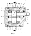
- FIG. 1 is a longitudinal section of a trained as a gear machine 1 hydraulic working machine according to one embodiment shown.
- the gear machine 1 is an external gear machine. This has a machine housing 2, which is closed by means of two housing cover 4 and 6.
- the Indian FIG. 1 right housing cover 6 of the gear machine 1 is penetrated by a first bearing shaft 8, on which a first gear 10 is disposed within the machine housing 2.
- the first gear 10 is connected to a second gear 12 via a toothing 14 into engagement, wherein the gear 12 is rotatably mounted on a second bearing shaft 16.
- the first and second bearing shaft 8 and 16 are each guided in two plain bearings 18, 20 and 22, 24.
- the in the FIG. 1 Right sliding bearing 20, 24 are in a bearing body 26 and in the FIG.
- the gears 10 and 12 are in the axial direction in each case via a first gear outer side 30 and 32 on a bearing end face 33 of the second bearing body 26 (right) and via a respective second gear outside 34 and 36 on a bearing face 37 of the first bearing body 28 (left) respectively sliding stored.
- the bearing bodies 26 and 28 each have an end face 38 or 40 towards the housing covers 6 and 4, respectively.
- the housing cover 4, 6 are aligned by centering bolts 42 on the machine housing 2. Between the housing covers 4 and 6 and the machine housing 2, a housing seal 44 is arranged. Furthermore, an axial field seal 46 is respectively introduced into the end faces 38 and 40 of the bearing bodies 26 and 28 for the separation of a high-pressure region of the gearwheel machine 1. A shaft seal 48 seals the passage of the first bearing shaft 8 through in the FIG. 1 right housing cover 6 from.
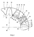
- FIG. 2 shows a cross-sectional view along the section line AA FIG. 1 by the gear machine 1, wherein for simplicity, only in the FIG. 1 upper gear 10 and the off FIG. 1 right bearing body 26 are shown in sections.
- a plurality of groove-shaped or elongated pockets 50 in the region of an annular surface 52 are introduced.
- the pockets 50 could also be approximately round.
- the annular surface 52 has an inner radius corresponding to a radius of a root circle 54 of the toothed wheel 10 and an outer radius corresponding to a radius of an outer circle 56 of the toothed wheel 10.
- the pockets 50 extend substantially in sections circumferentially about an axis of rotation 58 of the gear 10th
- the arrangement of the pockets 50 in the gear machine 1 from FIG. 1 can be designed differently. Thus, these may be arranged in one or more fields 60, with the field (s) 60 extending in the circumferential direction either over the entire annular surface 52 or over certain annular surface portions. Furthermore, the pockets 50 or fields 60 in one or both bearing end faces 33 and 37 of the bearing bodies 26 and 28, respectively FIG. 1 and in each case opposite of one or both gear outer sides 30, 32 and 34, 36 can be introduced.
- the pockets 50 act as lubricant reservoirs, which, like hydrostatic bearings, improve the tribological properties of the friction contact.
- box 60 with pockets 50 is shown.
- the pockets 50 are shown translucent. In use of the gear machine 1 as a gear pump, this cutout would be a high pressure area.
- the pockets 50 are arranged radially in four spaced-apart rows, with two or more pockets 50 alternately formed in the rows, and with a pocket 50 disposed in the outermost row in the radial direction.
- a tooth 62 of the gear 10 is in FIG. 2 approximately opposite from the field 60 for explaining the operation of the pockets 50 shown.
- the length in the circumferential direction of the gear 10 of a radially outermost pocket 64 and arranged in the next but one row of the field 60 pocket 66 is greater than the width of the tooth 62 in the region of the respective pocket 64 and 66.
- This causes the Pockets 64 and 66 in the in FIG. 1 shown position of the gear 10 and the tooth 62 connect the tooth 62 limited tooth spaces 68, 70 with each other.
- a throttled pressure medium connection between the tooth gaps 68, 70 is created. Through this connection, the higher pressure in the in FIG.
- all or certain tooth gaps of the gearwheel 10 can thus be connected to each other in a throttled manner.
- This is dependent on the number and arrangement of long pockets 50 (such as pockets 64 and 66).
- the long pockets 50 are, for example, each in a row circulating about the axis of rotation 58 can be arranged. It is also conceivable to arrange long pockets 50 only in the high-pressure region of the gear machine 1.
- the pockets 50 are each bounded only by the front tooth flank 72 in the direction of rotation Tooth gap 70 of a moving tooth 60 over the field and then with the limited by a direction of rotation in the rear tooth flank 74 tooth gap 68 in fluid communication. Except for the long pockets 64, 66, the pockets 50 are completely covered by the corresponding tooth during a rotational movement of the toothed wheel 10 during the transition from the pressure medium connection from the tooth gap 70 to the tooth gap 68.
- a compressive force acts on the tooth 50 of the toothed wheel 10 sliding over the pockets 50, due to the sectional or permanent pressure medium connection to the tooth space 68 or 70.
- the pressure force results in a force resulting from hydraulic forces acting on the toothed wheels 10, 12 (see FIG FIG. 1 and 2 ) acting axial force counteracted.
- the number, the size and / or the distribution of the pockets 50 can be designed such that the axial force is substantially compensated and thus the friction between the gears 10, 12 and the bearing bodies 26, 28 is minimized.
- the gear outer sides 30, 32 and 34, 36 of the gears 10 and 12, respectively endure higher pressures due to the pressure in the pockets 50, resulting in less wear.
- the force acting on the teeth of the gear 10 compressive force is represented by a representation of isobars 76, 78, 80 in the FIG. 2 clarified. These extend into FIG. 2 each of a gear ring surface 82, via a counter to the rotational direction of the tooth 62 adjacent tooth 84 to the tooth 62.
- the gear ring surface 82 has an outer radius 86 of the sliding bearing 20 corresponding inner radius and a radius of the predominantly Vietnamese Bengales 54 corresponding outer radius.
- the isobar 80 shown farthest from the axis of rotation 58 in the radial direction is slightly spaced from the tooth flanks 72, 74 of the tooth 84.
- the pressure between the tooth 84 and the bearing body 26 thus corresponds in a wide range to the pressure in the region of the outer radius If the course of the isobars 80 is further traced to the tooth 62 positioned over the pockets 50, it can be determined that the isobars 80 pass through only one foot region 88 of the tooth 62. Thus, the pressure effect of the pressure medium on the pockets 50 on the remaining portion of the tooth 62 can be seen.
- the bags 50 are made substantially cost neutral, by training in an aluminum die casting tool of the bearing body 26, 28 from FIG. 1 ,
- the pockets could also be introduced by the casting process by embossing or with a laser in the bearing end faces 33, 37.
- a hydraulic gear machine This has two meshing gears, which are mounted on gear outer surfaces between bearing end faces of bearing bodies. In at least one bearing end face a plurality of pockets are introduced in the region of at least one gear outer surface, which act as a kind of lubricant depot and in which a force acting on the gears pressure field can be formed.
Landscapes
- Engineering & Computer Science (AREA)
- Mechanical Engineering (AREA)
- General Engineering & Computer Science (AREA)
- Rotary Pumps (AREA)
Applications Claiming Priority (1)
| Application Number | Priority Date | Filing Date | Title |
|---|---|---|---|
| DE200910037199 DE102009037199A1 (de) | 2009-08-12 | 2009-08-12 | Hydraulische Zahnradmaschine |
Publications (1)
| Publication Number | Publication Date |
|---|---|
| EP2295802A2 true EP2295802A2 (fr) | 2011-03-16 |
Family
ID=43067553
Family Applications (1)
| Application Number | Title | Priority Date | Filing Date |
|---|---|---|---|
| EP20100007304 Withdrawn EP2295802A2 (fr) | 2009-08-12 | 2010-07-15 | Machine hydraulique à engrenages |
Country Status (2)
| Country | Link |
|---|---|
| EP (1) | EP2295802A2 (fr) |
| DE (1) | DE102009037199A1 (fr) |
Cited By (2)
| Publication number | Priority date | Publication date | Assignee | Title |
|---|---|---|---|---|
| EP4137697A1 (fr) * | 2021-08-16 | 2023-02-22 | Hamilton Sundstrand Corporation | Pompe à carburant avec indentation d'engrenage et de palier pour induire un film fluide |
| US11662026B2 (en) | 2021-08-16 | 2023-05-30 | Hamilton Sandstrand Corporation | Seal with surface indents |
Families Citing this family (2)
| Publication number | Priority date | Publication date | Assignee | Title |
|---|---|---|---|---|
| DE102012206137B4 (de) * | 2012-04-16 | 2014-12-31 | Robert Bosch Gmbh | Verfahren zur Herstellung eines verzahnten Bauteils sowie derartiges Bauteil |
| WO2015082257A1 (fr) * | 2013-12-03 | 2015-06-11 | Oerlikon Textile Gmbh & Co. Kg | Pompe à engrenage |
Citations (1)
| Publication number | Priority date | Publication date | Assignee | Title |
|---|---|---|---|---|
| DE19609992B4 (de) | 1996-03-14 | 2005-09-08 | Robert Bosch Gmbh | Zahnradmaschine |
-
2009
- 2009-08-12 DE DE200910037199 patent/DE102009037199A1/de not_active Withdrawn
-
2010
- 2010-07-15 EP EP20100007304 patent/EP2295802A2/fr not_active Withdrawn
Patent Citations (1)
| Publication number | Priority date | Publication date | Assignee | Title |
|---|---|---|---|---|
| DE19609992B4 (de) | 1996-03-14 | 2005-09-08 | Robert Bosch Gmbh | Zahnradmaschine |
Cited By (3)
| Publication number | Priority date | Publication date | Assignee | Title |
|---|---|---|---|---|
| EP4137697A1 (fr) * | 2021-08-16 | 2023-02-22 | Hamilton Sundstrand Corporation | Pompe à carburant avec indentation d'engrenage et de palier pour induire un film fluide |
| US11662026B2 (en) | 2021-08-16 | 2023-05-30 | Hamilton Sandstrand Corporation | Seal with surface indents |
| US11713716B2 (en) | 2021-08-16 | 2023-08-01 | Hamilton Sundstrand Corporation | Gear and bearing indents to induce fluid film |
Also Published As
| Publication number | Publication date |
|---|---|
| DE102009037199A1 (de) | 2011-02-17 |
Similar Documents
| Publication | Publication Date | Title |
|---|---|---|
| EP2221510B1 (fr) | Satellite doté d'un boulon d'appui comportant un écrou axial | |
| EP2406497A2 (fr) | Machine hydraulique à engrenage | |
| WO2010102723A2 (fr) | Machine hydraulique à engrenage | |
| DE19750834C1 (de) | Mechanisches Sperrdifferential | |
| DE2258135A1 (de) | Mehrgaengiges rotor-schraubentriebwerk | |
| EP0433576B1 (fr) | Pompe à engrenages annulaires pour moteurs à combustion interne et transmissions automatiques | |
| EP3384159B1 (fr) | Pompe à engrenages extérieurs | |
| DD141941A5 (de) | Innenachsige maschine mit schraubenfoermigem profil am rotor und im stator | |
| EP2295802A2 (fr) | Machine hydraulique à engrenages | |
| DE10302192B4 (de) | Planetengetriebe mit einer Ausgleichskupplung | |
| DE102012206699B4 (de) | Zahnradmaschine mit wannenartiger Vertiefung an der Außenoberfläche des Gehäuses | |
| EP1261806B1 (fr) | Ensemble rotor a denture inverse | |
| EP1328730B1 (fr) | Pompe a engrenages interieurs depourvue d'element de separation | |
| EP4314560B1 (fr) | Machine fluidique à engrenages intérieurs et procédé de fabrication d'une machine fluidique à engrenages intérieurs | |
| DE102018212497B4 (de) | Fluidfördereinrichtung | |
| DE102005056909A1 (de) | Hydraulische Zahnradmaschine | |
| EP2556256B1 (fr) | Pompe à pistons rotatifs et procédé de fonctionnement d'une pompe à pistons rotatifs | |
| DE3810169A1 (de) | Selbstsperrendes differentialgetriebe | |
| DE102013202917A1 (de) | Zahnradmaschine mit erhöhter Partikelrobustheit | |
| WO2021023338A1 (fr) | Agencement de transmission compact doté d'un train planétaire étagé et d'un différentiel à engrenage droit | |
| EP2625427B1 (fr) | Transmission hydraulique | |
| DE102012207079A1 (de) | Zahnradmaschine mit elastisch nachgiebigem Wandabschnitt | |
| DE102009047626A1 (de) | Zahnradpumpe | |
| DE102016213611A1 (de) | Rotorpumpe und Anordnung zum Antrieb einer Rotorpumpe | |
| DE19825667C2 (de) | Hydraulischer Druckerzeuger |
Legal Events
| Date | Code | Title | Description |
|---|---|---|---|
| PUAI | Public reference made under article 153(3) epc to a published international application that has entered the european phase |
Free format text: ORIGINAL CODE: 0009012 |
|
| AK | Designated contracting states |
Kind code of ref document: A2 Designated state(s): AL AT BE BG CH CY CZ DE DK EE ES FI FR GB GR HR HU IE IS IT LI LT LU LV MC MK MT NL NO PL PT RO SE SI SK SM TR |
|
| AX | Request for extension of the european patent |
Extension state: BA ME RS |
|
| STAA | Information on the status of an ep patent application or granted ep patent |
Free format text: STATUS: THE APPLICATION IS DEEMED TO BE WITHDRAWN |
|
| 18D | Application deemed to be withdrawn |
Effective date: 20150203 |