EP2295820A2 - Dispositif de sécurité pour systèmes hydrauliques dotés d'un élément de couplage - Google Patents
Dispositif de sécurité pour systèmes hydrauliques dotés d'un élément de couplage Download PDFInfo
- Publication number
- EP2295820A2 EP2295820A2 EP10009273A EP10009273A EP2295820A2 EP 2295820 A2 EP2295820 A2 EP 2295820A2 EP 10009273 A EP10009273 A EP 10009273A EP 10009273 A EP10009273 A EP 10009273A EP 2295820 A2 EP2295820 A2 EP 2295820A2
- Authority
- EP
- European Patent Office
- Prior art keywords
- coupling element
- safety device
- valve body
- valve
- pressure
- Prior art date
- Legal status (The legal status is an assumption and is not a legal conclusion. Google has not performed a legal analysis and makes no representation as to the accuracy of the status listed.)
- Withdrawn
Links
- 230000008878 coupling Effects 0.000 title claims abstract description 30
- 238000010168 coupling process Methods 0.000 title claims abstract description 30
- 238000005859 coupling reaction Methods 0.000 title claims abstract description 30
- 239000004519 grease Substances 0.000 claims abstract description 10
- 238000010276 construction Methods 0.000 claims description 2
- 239000002184 metal Substances 0.000 abstract description 2
- 238000009530 blood pressure measurement Methods 0.000 description 5
- 238000009434 installation Methods 0.000 description 2
- 238000012423 maintenance Methods 0.000 description 2
- 230000001419 dependent effect Effects 0.000 description 1
- 230000000694 effects Effects 0.000 description 1
- 238000005259 measurement Methods 0.000 description 1
- 238000000034 method Methods 0.000 description 1
Images

Classifications
-
- F—MECHANICAL ENGINEERING; LIGHTING; HEATING; WEAPONS; BLASTING
- F16—ENGINEERING ELEMENTS AND UNITS; GENERAL MEASURES FOR PRODUCING AND MAINTAINING EFFECTIVE FUNCTIONING OF MACHINES OR INSTALLATIONS; THERMAL INSULATION IN GENERAL
- F16K—VALVES; TAPS; COCKS; ACTUATING-FLOATS; DEVICES FOR VENTING OR AERATING
- F16K15/00—Check valves
- F16K15/02—Check valves with guided rigid valve members
- F16K15/025—Check valves with guided rigid valve members the valve being loaded by a spring
- F16K15/026—Check valves with guided rigid valve members the valve being loaded by a spring the valve member being a movable body around which the medium flows when the valve is open
-
- E—FIXED CONSTRUCTIONS
- E02—HYDRAULIC ENGINEERING; FOUNDATIONS; SOIL SHIFTING
- E02F—DREDGING; SOIL-SHIFTING
- E02F9/00—Component parts of dredgers or soil-shifting machines, not restricted to one of the kinds covered by groups E02F3/00 - E02F7/00
- E02F9/20—Drives; Control devices
- E02F9/22—Hydraulic or pneumatic drives
- E02F9/2264—Arrangements or adaptations of elements for hydraulic drives
- E02F9/2267—Valves or distributors
-
- F—MECHANICAL ENGINEERING; LIGHTING; HEATING; WEAPONS; BLASTING
- F15—FLUID-PRESSURE ACTUATORS; HYDRAULICS OR PNEUMATICS IN GENERAL
- F15B—SYSTEMS ACTING BY MEANS OF FLUIDS IN GENERAL; FLUID-PRESSURE ACTUATORS, e.g. SERVOMOTORS; DETAILS OF FLUID-PRESSURE SYSTEMS, NOT OTHERWISE PROVIDED FOR
- F15B13/00—Details of servomotor systems ; Valves for servomotor systems
- F15B13/02—Fluid distribution or supply devices characterised by their adaptation to the control of servomotors
- F15B13/024—Pressure relief valves
-
- F—MECHANICAL ENGINEERING; LIGHTING; HEATING; WEAPONS; BLASTING
- F15—FLUID-PRESSURE ACTUATORS; HYDRAULICS OR PNEUMATICS IN GENERAL
- F15B—SYSTEMS ACTING BY MEANS OF FLUIDS IN GENERAL; FLUID-PRESSURE ACTUATORS, e.g. SERVOMOTORS; DETAILS OF FLUID-PRESSURE SYSTEMS, NOT OTHERWISE PROVIDED FOR
- F15B13/00—Details of servomotor systems ; Valves for servomotor systems
- F15B13/02—Fluid distribution or supply devices characterised by their adaptation to the control of servomotors
- F15B13/027—Check valves
-
- F—MECHANICAL ENGINEERING; LIGHTING; HEATING; WEAPONS; BLASTING
- F16—ENGINEERING ELEMENTS AND UNITS; GENERAL MEASURES FOR PRODUCING AND MAINTAINING EFFECTIVE FUNCTIONING OF MACHINES OR INSTALLATIONS; THERMAL INSULATION IN GENERAL
- F16K—VALVES; TAPS; COCKS; ACTUATING-FLOATS; DEVICES FOR VENTING OR AERATING
- F16K17/00—Safety valves; Equalising valves, e.g. pressure relief valves
- F16K17/02—Safety valves; Equalising valves, e.g. pressure relief valves opening on surplus pressure on one side; closing on insufficient pressure on one side
- F16K17/04—Safety valves; Equalising valves, e.g. pressure relief valves opening on surplus pressure on one side; closing on insufficient pressure on one side spring-loaded
- F16K17/0406—Safety valves; Equalising valves, e.g. pressure relief valves opening on surplus pressure on one side; closing on insufficient pressure on one side spring-loaded in the form of balls
-
- F—MECHANICAL ENGINEERING; LIGHTING; HEATING; WEAPONS; BLASTING
- F16—ENGINEERING ELEMENTS AND UNITS; GENERAL MEASURES FOR PRODUCING AND MAINTAINING EFFECTIVE FUNCTIONING OF MACHINES OR INSTALLATIONS; THERMAL INSULATION IN GENERAL
- F16K—VALVES; TAPS; COCKS; ACTUATING-FLOATS; DEVICES FOR VENTING OR AERATING
- F16K17/00—Safety valves; Equalising valves, e.g. pressure relief valves
- F16K17/02—Safety valves; Equalising valves, e.g. pressure relief valves opening on surplus pressure on one side; closing on insufficient pressure on one side
- F16K17/04—Safety valves; Equalising valves, e.g. pressure relief valves opening on surplus pressure on one side; closing on insufficient pressure on one side spring-loaded
- F16K17/0473—Multiple-way safety valves
Definitions
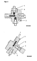
- the invention relates to an improved safety device for hydraulic systems with coupling element and securing the pressure relief valve setting, preferably for chain-driven construction machines on the clamping element of the stator, for direct pressure measurement in a fat chamber of the clamping element.
- valve couplings such as minimess connections
- Valve couplings of this type are used for example in the DE 3218115 C2 and DE 102005012238 B4 described.
- This previously practiced procedure and measuring arrangement has the disadvantage that it is a great installation effort, which must ensure access to the grease chamber is connected.
- a pressure measurement during maintenance work is possible only with great effort, since a pressure-free state of the hydraulic system must be established for the installation of a measuring connection. This is difficult and time consuming due to the design and access to the clamping elements.
- the known pressure measurements has also proved to be disadvantageous that the measurement results are afflicted when measuring the pressure through the existing check valves with errors.
- the invention has for its object to develop an improved safety device with coupling element for a direct check of the internal pressure of a grease chamber in the use of clamping elements. Furthermore, the object is to additionally secure the pressure relief valve setting in order to prevent or prove an improper adjustment to the overpressure or relief valve of the safety device.
- the object is achieved by a combination of known components, consisting of a safety device which is equipped in a valve body with biasing, non-return and pressure relief valve, and a coupling element for connecting a pressure gauge, that in the valve body of the safety valve, a coupling element is integrated , with direct access via the safety valve to the fat chamber.
- the coupling element can be screwed into a bore with an internal thread and / or firmly integrated.
- safety valves can be used with positive and positive pressure valves for hydraulic systems.
- Minimess couplings As coupling elements known or commercially available Minimess couplings, valve couplings, measuring couplings or hose couplings can be used depending on the application and intended use.
- the safety device according to the invention can also be rotatable on the tensioning element in order to optimize the position of the coupling element or of the measuring port in the installed state.
- the safety device according to the invention has been improved to the effect that the lock nut is fixed to the pressure relief valve in position with a metal position pin.
- a twisting is no longer possible. If it nevertheless comes under force to adjust the lock nut, then bends or shears off the position pin.
- improper handling of the safety device is easier to detect for customers than before.
- the inventive combination of known components represents a cost-effective and improved safety device for practical use. This is a simple handling and control of the pressure conditions in the Grease chamber ensured by the valve coupling on the safety device.
- a great advantage of the solution according to the invention is that in each working and maintenance phase, a direct pressure measurement can be made without measuring errors.
- To the coupling element pressure gauge or other commercially available pressure gauges can be connected.
- a quick and direct access to the internal pressure conditions of the grease chamber of the chain tensioner via the safety device according to the invention at any time without additional assembly and disassembly effort is possible.
- the solution according to the invention offers a variety of possible applications.
Landscapes
- Engineering & Computer Science (AREA)
- General Engineering & Computer Science (AREA)
- Mechanical Engineering (AREA)
- Physics & Mathematics (AREA)
- Fluid Mechanics (AREA)
- Mining & Mineral Resources (AREA)
- Civil Engineering (AREA)
- Structural Engineering (AREA)
- Safety Valves (AREA)
- Fluid-Pressure Circuits (AREA)
Applications Claiming Priority (1)
| Application Number | Priority Date | Filing Date | Title |
|---|---|---|---|
| DE202009012329U DE202009012329U1 (de) | 2009-09-10 | 2009-09-10 | Sicherheitseinrichtung für Hydrauliksysteme mit Kupplungselement |
Publications (2)
| Publication Number | Publication Date |
|---|---|
| EP2295820A2 true EP2295820A2 (fr) | 2011-03-16 |
| EP2295820A3 EP2295820A3 (fr) | 2011-09-07 |
Family
ID=41694133
Family Applications (1)
| Application Number | Title | Priority Date | Filing Date |
|---|---|---|---|
| EP10009273A Withdrawn EP2295820A3 (fr) | 2009-09-10 | 2010-09-07 | Dispositif de sécurité pour systèmes hydrauliques dotés d'un élément de couplage |
Country Status (2)
| Country | Link |
|---|---|
| EP (1) | EP2295820A3 (fr) |
| DE (1) | DE202009012329U1 (fr) |
Cited By (1)
| Publication number | Priority date | Publication date | Assignee | Title |
|---|---|---|---|---|
| CN111779724A (zh) * | 2020-07-09 | 2020-10-16 | 燕山大学 | 一种航空电静液作动系统用液压集成阀块 |
Families Citing this family (3)
| Publication number | Priority date | Publication date | Assignee | Title |
|---|---|---|---|---|
| DE202011000643U1 (de) * | 2011-03-22 | 2011-10-21 | Elastotec Gmbh | Sicherheitsventil |
| DE102017007382A1 (de) | 2017-08-05 | 2019-02-07 | Nikolai Kubasiak | Sicherheitseinrichtung für Hochdruckanwendungen |
| DE102020005355B4 (de) | 2020-08-28 | 2024-03-14 | Meycotec Gmbh | Hochdrucksicherheitseinrichtungen für Elastomer-, Spiralfeder- und Gasspannsysteme |
Citations (2)
| Publication number | Priority date | Publication date | Assignee | Title |
|---|---|---|---|---|
| DE3218115C2 (de) | 1982-05-13 | 1985-12-05 | Hydrotechnik Gmbh, 6250 Limburg | Ventilkupplung für fluidische Systeme |
| DE102005012238B4 (de) | 2005-03-15 | 2009-04-30 | Gisela Weber | Minimess-Anschluss für Hydraulikeinheiten |
Family Cites Families (3)
| Publication number | Priority date | Publication date | Assignee | Title |
|---|---|---|---|---|
| DE2553043A1 (de) * | 1975-11-26 | 1977-06-02 | Hydrotechnik Gmbh | Kupplung zum herstellen eines anschlusses an ein unter druck stehendes system |
| DE4303366C2 (de) * | 1993-02-05 | 1997-01-02 | Hydrotechnik Gmbh | Ventil- und Meßkupplung |
| DE202009002473U1 (de) * | 2009-02-20 | 2009-04-23 | Meycotec Gmbh Maschinenbau | Sicherheitsventil für Hydrauliksysteme |
-
2009
- 2009-09-10 DE DE202009012329U patent/DE202009012329U1/de not_active Expired - Lifetime
-
2010
- 2010-09-07 EP EP10009273A patent/EP2295820A3/fr not_active Withdrawn
Patent Citations (2)
| Publication number | Priority date | Publication date | Assignee | Title |
|---|---|---|---|---|
| DE3218115C2 (de) | 1982-05-13 | 1985-12-05 | Hydrotechnik Gmbh, 6250 Limburg | Ventilkupplung für fluidische Systeme |
| DE102005012238B4 (de) | 2005-03-15 | 2009-04-30 | Gisela Weber | Minimess-Anschluss für Hydraulikeinheiten |
Cited By (1)
| Publication number | Priority date | Publication date | Assignee | Title |
|---|---|---|---|---|
| CN111779724A (zh) * | 2020-07-09 | 2020-10-16 | 燕山大学 | 一种航空电静液作动系统用液压集成阀块 |
Also Published As
| Publication number | Publication date |
|---|---|
| EP2295820A3 (fr) | 2011-09-07 |
| DE202009012329U1 (de) | 2010-02-18 |
Similar Documents
| Publication | Publication Date | Title |
|---|---|---|
| DE202015002535U1 (de) | Befestigungsvorrichtung zur Befestigung eines Rotorblattesan einer Rotornabe einer Windkraftanlage | |
| EP2295820A2 (fr) | Dispositif de sécurité pour systèmes hydrauliques dotés d'un élément de couplage | |
| DE202013009630U1 (de) | Schlauchleitung | |
| DE2937443C2 (de) | Mit einem Gewindeanschluß versehenes Gehäuse aus Kunststoff, insbesondere Ventilgehäuse | |
| DE102008027123B4 (de) | Vorrichtung zum Befestigen eines Bauteiles, insbesondere einer Haltekonsole für Nebenaggregate eines Fahrzeuges, insbesondere eines Nutz- oder Kraftfahrzeuges | |
| WO2004106132A1 (fr) | Dispositif de freinage de vehicule sur rail | |
| DE102011056712A1 (de) | Ventilabdeckung für eine Spülpumpe beim Tiefbohrbetrieb | |
| DE102009060755B4 (de) | Ventilanordnung und Werkzeugset | |
| WO2017054927A2 (fr) | Unité de calage de paliers à roulement sur des axes et des arbres | |
| DE2352558A1 (de) | Fluessigkeitskupplung mit bruchsicherung | |
| EP3683441B1 (fr) | Unité de montage en tant que module pour une pompe à lubrifiant | |
| EP2423546A2 (fr) | Soupape, en particulier soupape de raccord de tuyaux flexibles | |
| EP3380805A1 (fr) | Ensemble de mesure comprenant un palpeur de mesure tactile et un collier de fixation ainsi que collier de fixation pour un palpeur de mesure tactile | |
| DE102015217786A1 (de) | Vorrichtung zur Herstellung einer Axialverbindung, insbesondere in einem Kältemittelkreislauf eines Kraftfahrzeugs | |
| DE102014212891A1 (de) | Elastomerlager | |
| DE202011051340U1 (de) | Multifunktionsadapter für den Anschluss von Hydraulikleitungen | |
| WO2011160610A1 (fr) | Élément de liaison | |
| DE102010051615A1 (de) | Fügeverbindung für eine Kolbenführungseinheit in einem Gehäuse | |
| EP2754938B1 (fr) | Produit assemblé comprenant un raccord taraudé et une douille taraudée, et sytème hydraulique associé | |
| DE3344111A1 (de) | Bremsschlauch | |
| DE102005059957B4 (de) | Halteblech einer ein Gehäuse aufweisenden elektrohydraulischen Steuervorrichtung | |
| DE102007062355B4 (de) | Anordnung einer Scheibenventileinrichtung an einem Getriebegehäuse | |
| DE102012100077A1 (de) | Handrad | |
| EP2192353B1 (fr) | Dispositif de détermination de la différence de pression sur une installation d'eau chaude | |
| DE102016113370B4 (de) | Verfahren zum Überprüfen einer Position eines Schneidringes und eine Schneidringlehre |
Legal Events
| Date | Code | Title | Description |
|---|---|---|---|
| PUAI | Public reference made under article 153(3) epc to a published international application that has entered the european phase |
Free format text: ORIGINAL CODE: 0009012 |
|
| AK | Designated contracting states |
Kind code of ref document: A2 Designated state(s): AL AT BE BG CH CY CZ DE DK EE ES FI FR GB GR HR HU IE IS IT LI LT LU LV MC MK MT NL NO PL PT RO SE SI SK SM TR |
|
| AX | Request for extension of the european patent |
Extension state: BA ME RS |
|
| RIN1 | Information on inventor provided before grant (corrected) |
Inventor name: LERCHE, EIKE Inventor name: KUBASIAK, HARALD |
|
| PUAL | Search report despatched |
Free format text: ORIGINAL CODE: 0009013 |
|
| AK | Designated contracting states |
Kind code of ref document: A3 Designated state(s): AL AT BE BG CH CY CZ DE DK EE ES FI FR GB GR HR HU IE IS IT LI LT LU LV MC MK MT NL NO PL PT RO SE SI SK SM TR |
|
| AX | Request for extension of the european patent |
Extension state: BA ME RS |
|
| RIC1 | Information provided on ipc code assigned before grant |
Ipc: F15B 13/02 20060101AFI20110729BHEP |
|
| 17P | Request for examination filed |
Effective date: 20111014 |
|
| TPAC | Observations by third parties |
Free format text: ORIGINAL CODE: EPIDOSNTIPA |
|
| STAA | Information on the status of an ep patent application or granted ep patent |
Free format text: STATUS: THE APPLICATION IS DEEMED TO BE WITHDRAWN |
|
| 18D | Application deemed to be withdrawn |
Effective date: 20150401 |