EP2295826A2 - Ressort en matière synthétique pour un châssis de véhicule automobile - Google Patents
Ressort en matière synthétique pour un châssis de véhicule automobile Download PDFInfo
- Publication number
- EP2295826A2 EP2295826A2 EP10175524A EP10175524A EP2295826A2 EP 2295826 A2 EP2295826 A2 EP 2295826A2 EP 10175524 A EP10175524 A EP 10175524A EP 10175524 A EP10175524 A EP 10175524A EP 2295826 A2 EP2295826 A2 EP 2295826A2
- Authority
- EP
- European Patent Office
- Prior art keywords
- plastic spring
- spring according
- plastic
- spring
- corrugated pipe
- Prior art date
- Legal status (The legal status is an assumption and is not a legal conclusion. Google has not performed a legal analysis and makes no representation as to the accuracy of the status listed.)
- Withdrawn
Links
- 239000004033 plastic Substances 0.000 title claims abstract description 92
- 229920003023 plastic Polymers 0.000 title claims abstract description 92
- 238000006073 displacement reaction Methods 0.000 claims abstract description 3
- 239000000835 fiber Substances 0.000 claims description 19
- 238000009423 ventilation Methods 0.000 claims description 17
- 230000002787 reinforcement Effects 0.000 claims description 12
- 239000004744 fabric Substances 0.000 claims description 3
- 239000000314 lubricant Substances 0.000 claims description 3
- 238000004804 winding Methods 0.000 claims description 3
- 230000005540 biological transmission Effects 0.000 claims 1
- 230000006835 compression Effects 0.000 description 6
- 238000007906 compression Methods 0.000 description 6
- 239000000725 suspension Substances 0.000 description 6
- 238000013016 damping Methods 0.000 description 4
- 230000006870 function Effects 0.000 description 3
- 229920002430 Fibre-reinforced plastic Polymers 0.000 description 1
- 230000004308 accommodation Effects 0.000 description 1
- 239000000853 adhesive Substances 0.000 description 1
- 230000001070 adhesive effect Effects 0.000 description 1
- 238000010276 construction Methods 0.000 description 1
- 230000000694 effects Effects 0.000 description 1
- 239000011151 fibre-reinforced plastic Substances 0.000 description 1
- 230000017525 heat dissipation Effects 0.000 description 1
- 238000009434 installation Methods 0.000 description 1
- 239000000463 material Substances 0.000 description 1
- 239000007769 metal material Substances 0.000 description 1
- 230000036316 preload Effects 0.000 description 1
- 230000009993 protective function Effects 0.000 description 1
- 230000035939 shock Effects 0.000 description 1
Images


Classifications
-
- F—MECHANICAL ENGINEERING; LIGHTING; HEATING; WEAPONS; BLASTING
- F16—ENGINEERING ELEMENTS AND UNITS; GENERAL MEASURES FOR PRODUCING AND MAINTAINING EFFECTIVE FUNCTIONING OF MACHINES OR INSTALLATIONS; THERMAL INSULATION IN GENERAL
- F16F—SPRINGS; SHOCK-ABSORBERS; MEANS FOR DAMPING VIBRATION
- F16F1/00—Springs
- F16F1/36—Springs made of rubber or other material having high internal friction, e.g. thermoplastic elastomers
- F16F1/366—Springs made of rubber or other material having high internal friction, e.g. thermoplastic elastomers made of fibre-reinforced plastics, i.e. characterised by their special construction from such materials
-
- F—MECHANICAL ENGINEERING; LIGHTING; HEATING; WEAPONS; BLASTING
- F16—ENGINEERING ELEMENTS AND UNITS; GENERAL MEASURES FOR PRODUCING AND MAINTAINING EFFECTIVE FUNCTIONING OF MACHINES OR INSTALLATIONS; THERMAL INSULATION IN GENERAL
- F16F—SPRINGS; SHOCK-ABSORBERS; MEANS FOR DAMPING VIBRATION
- F16F1/00—Springs
- F16F1/02—Springs made of steel or other material having low internal friction; Wound, torsion, leaf, cup, ring or the like springs, the material of the spring not being relevant
- F16F1/025—Springs made of steel or other material having low internal friction; Wound, torsion, leaf, cup, ring or the like springs, the material of the spring not being relevant characterised by having a particular shape
-
- F—MECHANICAL ENGINEERING; LIGHTING; HEATING; WEAPONS; BLASTING
- F16—ENGINEERING ELEMENTS AND UNITS; GENERAL MEASURES FOR PRODUCING AND MAINTAINING EFFECTIVE FUNCTIONING OF MACHINES OR INSTALLATIONS; THERMAL INSULATION IN GENERAL
- F16F—SPRINGS; SHOCK-ABSORBERS; MEANS FOR DAMPING VIBRATION
- F16F2230/00—Purpose; Design features
- F16F2230/0041—Locking; Fixing in position
Definitions
- the invention relates to a plastic spring according to the preamble of patent claim 1.
- From the DE-AS 1 009 500 is a suspension hollow body made of rubber or elastic plastic for absorbing shocks in vehicles known. It is a cylindrical hollow body with end connections. These end-side terminals prevent an arrangement in which a vibration damper is mounted coaxially with the spring.
- the GB 698,322 relates to a suspension hollow body made of rubber, which is axially braced between two spring plates.
- a first spring plate is on a cylinder and a second spring plate attached to a central rod of the suspension device.
- the suspension hollow body rests radially on the piston rod, so that friction forces between the piston rod and the suspension hollow body occur during each suspension movement.
- a strut with a height adjustable spring plate From the DE 101 44 163 C1 is known a strut with a height adjustable spring plate.
- the spring plate has a sleeve portion which is arranged in a cylinder-side chamber. By filling the chamber, the sleeve portion is axially displaced in the chamber and thus changed the bias of a helical compression spring.
- the spring plate is made of a metallic material, wherein the sleeve portion is formed from a circuit board by deep drawing. As a result, the usable length of the sleeve portion is unfortunately limited.
- the object of the present invention is to further develop a plastic spring such that use in a vehicle is possible in a mass-produced manner.
- a connection surface of the plastic spring is designed as a tubular body which engages in a pot element of one of the supporting components, wherein the pot element can be filled with a displacer mass and thereby the tubular body within the pot element a sliding movement for the axial adjustment of the bias the plastic spring performs.
- Plastic is preferably used as the displacer mass. This displacer mass connects easily to the tubular body, so that there is a permanent and non-rotating connection between the spring and the pot member of the supporting component.
- the tubular body is preferably made in one piece with the corrugated tube body.
- the big advantage of the invention is that a spring plate can be omitted in the classical construction as in a helical compression spring. In many applications, the spring must be placed exactly on a spring plate. Due to the one - part of the Pipe body with the resilient portion of the plastic spring is always the correct installation position and positioning of the spring guaranteed.
- the pot element is part of an outer cylinder of a strut, wherein the cylinder is also made of plastic.
- the cylinder is also made of plastic.
- the plastic spring has an axially extending fiber reinforcement whose fiber length substantially corresponds to the axial distance between the connection surfaces.
- the spring effect of the plastic spring is not determined by the Kunststoffanteiien, but by the Faserarmmaschine.
- the plastic components exert an adhesive function between the threads of the reinforcement. Furthermore, the plastic components seal the spaces within the fiber reinforcement so that the plastic spring provides protection against dirt.
- At least 50% of the axially extending fibers have an angular deviation of less than 30 ° to the longitudinal axis of the plastic spring.
- the plastic spring has a fiber reinforcement extending in the circumferential direction, wherein the fiber length corresponds at least to the winding diameter of the corrugated pipe body.
- the fiber reinforcement is undulating and is preferably formed by a fabric.
- the spring characteristic of the plastic spring can therefore be changed by the variation of various parameters.
- the fiber reinforcement can also influence the spring characteristic, e.g. by the number of reinforcement layers, through the threadline or the material selection.
- connection surface is designed as a thrust bearing.
- the plastic spring can serve as a support for the axial bearing. A separate component that must be fitted separately, z. B. to comply with a bearing clearance, is not necessary.
- connection surface may have an annular groove for receiving a bearing ring.
- the bearing ring forms a possible design of a plain bearing.
- connection surface has a roller bearing.
- an annular groove has a lubricant filling.
- connection surface has a latching mechanism for attachment to one of the mutually movable components. Separate clamping means, which fix the plastic spring on one of the mutually movable components, so unnecessary.
- the plastic spring should be specifically ventilated.
- the plastic spring on at least one vent opening, which is controlled by a check valve.
- the check valve is formed by an elastic valve body which is mounted in a fold of the corrugated pipe body.
- the corrugated tube body forms practically a part of the check valve.
- the ventilation opening is designed in a fold of the corrugated pipe body. If the ventilation opening is made in the radially extending annular regions of the corrugated pipe body, then the risk of lateral dirt entry is significantly minimized.
- this has a channel shape, which is supported with its groove bottom in the fold.
- a vibration damper as a cartridge may be disposed within the cylinder, wherein between an outer cylinder of the cartridge and the inner wall of the cylinder there is at least one ventilation duct connected to an inner space of the plastic spring.
- the vibration damper in connection with a cylinder made of plastic, the problem of heat dissipation is solved by the vibration damper.
- the ventilation channel has at least one connection opening to the surroundings of the cylinder.
- the plastic spring acts as an air pump for the ventilation channel and thus promotes the heat generated during operation of the vibration damper from the cylinder.
- the plastic spring in the operating state of the block length forms a throttle cross-section between at least two adjacent folds of the corrugated pipe body.
- the deformation work of the spring can also be used in the damping work when displacing air from the compressed folds.
- At least one groove is designed, which determines at least one residual cross-section between a volume enclosed by a fold and an area located outside of said fold.
- the groove cross section at block length determines the effective throttle cross section.
- the groove extends in a relaxed spring substantially parallel to the longitudinal axis.
- the at least one groove may be formed on the inner and / or outer wall of the corrugated pipe body.
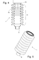
- the FIG. 1 shows a plastic spring 1, a corrugated tube body 3 and end-side pads 5; 7 for transmitting power between two relatively movable components 9; 11 has.
- the plastic spring 1 with a vibration damper 13 in the embodiment of a cartridge within a Cylinder 15 combined, the plastic spring 1 is also used in other applications.
- the plastic spring 1 has an axially extending Faserarmtechnik 16 whose fiber length substantially the axial distance between the pads 5; 7 corresponds.
- At least 50% of the axially extending fibers have an angular deviation of less than 30 ° to the longitudinal axis of the plastic spring.
- plastic spring may have a circumferentially extending Faserarmtechnik 18, wherein the fiber length corresponds at least to the winding diameter of the corrugated pipe body 3.
- the fiber reinforcements 16; 18 are embedded in fabric form in the plastic spring.
- the plastic spring In addition to its spring function, based on the Faserarmtechniken 16; 18, the plastic spring also has a protective function for the component and components covered by it.
- the pad 5 is, as in the FIGS. 4 and 5 becomes particularly clear when running a tubular body.
- This tubular body 5 engages in a cylinder-side pot element 17.
- a receiving space 19 of the pot element 17 can be filled via at least one opening 21 with a urformbaren displacer mass ( Fig. 2 ).
- the tubular body 5 carries out an axial displacement movement within the pot element 17, via which the pretensioning of the plastic spring 1 can be adjusted.
- the tubular body 5 is made in one piece with the corrugated pipe body 3, so that in particular in the combination of a cylinder 15, which is also made of plastic, a particularly resilient connection between the said components 5, 15 can be produced, the unauthorized disassembly of the plastic spring 1 effectively prevented.
- connection surface 7 of the plastic spring 1 which is in operative connection with a Anschlußorga 23 a piston rod 25 of the vibration damper 13.
- a thrust bearing 27 is executed.
- the connection surface has an annular groove 29 in which z.
- a bearing ring 31 or a lubricant filling is included.
- a roller bearing can be designed in the connection surface, so that a particularly low-friction rotational relative movement between the plastic spring 1 and the connecting member 23 is possible.
- a latching connection 30 holds the plastic spring on the connecting member 23rd
- FIGS. 6 to 9 show that the plastic spring 1 can have at least one ventilation opening 33, which is controlled by a check valve 35.
- the ventilation opening 33 may also be designed in the connection member 23, as the FIGS. 1 and 3 demonstrate.
- the check valve 35 is formed by an elastic valve body 37, which is mounted in a fold of the corrugated pipe body 3.
- Valve body 37 has a channel shape, which is supported with its groove bottom 39 in a fold of the corrugated pipe body 3.
- the ventilation opening 33 is also embodied in a fold of the corrugated pipe body, namely in the radially extending ribs of the corrugated pipe body 3.
- the illustrated variant shows an inside arrangement of the valve body 37, so that the excess volume of air can not escape through the vent opening 33 in a compression of the plastic spring 1, but is displaced in a ventilation channel 45, which is connected to an interior 47 of the plastic spring 1 , ( Fig. 1 ).
- the ventilation channel 45 is formed by at least one channel between an outer cylinder, the cartridge 13 and the cylinder 15, wherein the cylinder 15 has at least one connection opening 45 to the external environment.
- the plastic spring 1 acts as a pump, which dissipates the excess of air volume resulting in a vibration damper 13 heat from the cylinder 15.
- the plastic spring expands again, then raise the legs 41, 43 from the réellevvandung Weil body from, so that again a pressure equalization can be done to the environment through the open ventilation openings.
- a damping force, generated with the plastic spring 1 are used.
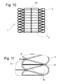
- the plastic spring 1 forms in the operating state of the block length, see Fig. 10 , At least one throttle cross-section 51 between adjacent folds of the corrugated pipe body 3.
- a throttle cross-section 51 may, for. B. are formed by at least one groove 53, which are determined at least one residual cross-section between a trapped volume of a fold and a region located outside of said fold.
- the groove extends in a relaxed spring substantially parallel to the longitudinal axis of the plastic spring.
- This at least one groove 53 may be formed on the inner as well as on the outer wall of the corrugated pipe body.
Landscapes
- Engineering & Computer Science (AREA)
- General Engineering & Computer Science (AREA)
- Mechanical Engineering (AREA)
- Vehicle Body Suspensions (AREA)
- Springs (AREA)
Applications Claiming Priority (1)
| Application Number | Priority Date | Filing Date | Title |
|---|---|---|---|
| DE102009029300A DE102009029300A1 (de) | 2009-09-09 | 2009-09-09 | Kunststofffeder für ein Kraftfahrzeugfahrwerk |
Publications (2)
| Publication Number | Publication Date |
|---|---|
| EP2295826A2 true EP2295826A2 (fr) | 2011-03-16 |
| EP2295826A3 EP2295826A3 (fr) | 2016-09-14 |
Family
ID=43033090
Family Applications (1)
| Application Number | Title | Priority Date | Filing Date |
|---|---|---|---|
| EP10175524.7A Withdrawn EP2295826A3 (fr) | 2009-09-09 | 2010-09-07 | Ressort en matière synthétique pour un châssis de véhicule automobile |
Country Status (3)
| Country | Link |
|---|---|
| US (1) | US8297600B2 (fr) |
| EP (1) | EP2295826A3 (fr) |
| DE (1) | DE102009029300A1 (fr) |
Families Citing this family (6)
| Publication number | Priority date | Publication date | Assignee | Title |
|---|---|---|---|---|
| US7102302B2 (en) | 2002-04-19 | 2006-09-05 | Thomson Licensing | Waveform generator for controlling an electron beam in a cathode ray tube |
| KR20130101684A (ko) * | 2012-03-06 | 2013-09-16 | 현대자동차주식회사 | 차량용 서스펜션의 스프링 |
| DE102014102330A1 (de) | 2014-02-24 | 2015-08-27 | ThyssenKrupp Federn und Stabilisatoren GmbH | Tragfedereinheit für ein Fahrzeugfahrwerk |
| DE102016002205B3 (de) * | 2016-02-25 | 2017-08-10 | Audi Ag | Federvorrichtung mit einem Wellrohrkörper |
| DE102016013721A1 (de) * | 2016-11-17 | 2018-05-17 | Grammer Ag | Feder, Verwendung eines Kunststoffschlauchs als Feder und Ausstattungsteil eines Fahrzeuginnenraums |
| DE102018213418B3 (de) | 2018-08-09 | 2019-10-17 | Ford Global Technologies, Llc | Baugruppe für eine Radaufhängung eines Fahrzeugs |
Citations (5)
| Publication number | Priority date | Publication date | Assignee | Title |
|---|---|---|---|---|
| GB698322A (en) | 1948-07-13 | 1953-10-14 | Jaroslav Frei | Suspension system |
| DE1009500B (de) | 1954-01-29 | 1957-05-29 | Wilhelm Herm Mueller & Co K G | Federungshohlkoerper aus Gummi oder elastischem Kunststoff, insbesondere zum Auffangen von Stoessen bei Fahrzeugen |
| DE1655642A1 (de) | 1967-11-09 | 1971-06-09 | Automobilbau Hohenstein Ernstt | Federelement,insbesondere zur Abfederung von Fahrzeugaufbauten |
| DE2340917A1 (de) | 1972-03-21 | 1975-02-20 | Hercules Inc | Kunststoffeder fuer sessel oder sofas |
| DE10144163C1 (de) | 2001-09-08 | 2003-04-10 | Zf Sachs Ag | Federbein mit höheneinstellbarem Federteller |
Family Cites Families (17)
| Publication number | Priority date | Publication date | Assignee | Title |
|---|---|---|---|---|
| DE1021733B (de) * | 1956-04-19 | 1957-12-27 | Wilhelm Herm Mueller & Co K G | Luftfederung fuer Fahrzeuge |
| DE1215533B (de) * | 1962-02-22 | 1966-04-28 | Linde Ag | Federungseinrichtung fuer ein lenkbares Rad der Vorderachse eines Schleppers |
| US3263983A (en) * | 1963-12-30 | 1966-08-02 | Ford Motor Co | Shock absorber and auxiliary spring unit |
| FR1558529A (fr) * | 1968-01-09 | 1969-02-28 | ||
| US4036335A (en) * | 1971-09-13 | 1977-07-19 | Arnold A. Cowan | Adjustable shock absorber |
| US4235426A (en) * | 1979-04-11 | 1980-11-25 | General Motors Corporation | Shock absorber with compression spring and dust tube |
| US4235427A (en) * | 1979-05-07 | 1980-11-25 | Walter Bialobrzeski | Spring |
| DE3515525A1 (de) * | 1985-04-30 | 1986-11-06 | Bayerische Motoren Werke AG, 8000 München | Federelement aus faserverbundwerkstoff |
| US4817928A (en) * | 1987-10-09 | 1989-04-04 | Paton H N | Suspension system |
| US5133573A (en) * | 1989-03-27 | 1992-07-28 | Mazda Motor Corporation | Strut mounting structure for a vehicle and method of assembly |
| JP2521236Y2 (ja) * | 1989-06-22 | 1996-12-25 | 東海ゴム工業株式会社 | バンパラバー |
| US5044614A (en) * | 1990-02-22 | 1991-09-03 | Rau John A | Shock absorber spring adjuster |
| US5996982A (en) * | 1997-07-29 | 1999-12-07 | Gabriel Ride Control Products, Inc. | Vehicle shock absorber with coil over preload adjustment |
| DE10227713B3 (de) * | 2002-06-21 | 2004-02-19 | Zf Sachs Ag | Federbein mit höheneinstellbarem Federteller |
| DE10301546B3 (de) * | 2003-01-16 | 2004-05-06 | Zf Sachs Ag | Federbein mit höhenverstellbarem Federteller |
| US20070267792A1 (en) * | 2005-08-13 | 2007-11-22 | Elmoselhy Salah A M | Sigma-springs for suspension systems |
| DE102008006411A1 (de) * | 2008-01-28 | 2009-07-30 | Muhr Und Bender Kg | Fahrzeugfeder aus Faserverbundwerkstoff |
-
2009
- 2009-09-09 DE DE102009029300A patent/DE102009029300A1/de not_active Ceased
-
2010
- 2010-09-07 EP EP10175524.7A patent/EP2295826A3/fr not_active Withdrawn
- 2010-09-09 US US12/878,401 patent/US8297600B2/en not_active Expired - Fee Related
Patent Citations (5)
| Publication number | Priority date | Publication date | Assignee | Title |
|---|---|---|---|---|
| GB698322A (en) | 1948-07-13 | 1953-10-14 | Jaroslav Frei | Suspension system |
| DE1009500B (de) | 1954-01-29 | 1957-05-29 | Wilhelm Herm Mueller & Co K G | Federungshohlkoerper aus Gummi oder elastischem Kunststoff, insbesondere zum Auffangen von Stoessen bei Fahrzeugen |
| DE1655642A1 (de) | 1967-11-09 | 1971-06-09 | Automobilbau Hohenstein Ernstt | Federelement,insbesondere zur Abfederung von Fahrzeugaufbauten |
| DE2340917A1 (de) | 1972-03-21 | 1975-02-20 | Hercules Inc | Kunststoffeder fuer sessel oder sofas |
| DE10144163C1 (de) | 2001-09-08 | 2003-04-10 | Zf Sachs Ag | Federbein mit höheneinstellbarem Federteller |
Also Published As
| Publication number | Publication date |
|---|---|
| US8297600B2 (en) | 2012-10-30 |
| US20110057369A1 (en) | 2011-03-10 |
| EP2295826A3 (fr) | 2016-09-14 |
| DE102009029300A1 (de) | 2011-04-07 |
Similar Documents
| Publication | Publication Date | Title |
|---|---|---|
| EP2427359B1 (fr) | Direction à crémaillère | |
| DE102007045892B4 (de) | Schwingungsdämpfer mit einem Zuganschlag | |
| EP2295826A2 (fr) | Ressort en matière synthétique pour un châssis de véhicule automobile | |
| DE10139861B4 (de) | Radaufhängung eines Kraftfahrzeugs | |
| EP3197747B1 (fr) | Direction a crémaillère pour véhicules automobiles | |
| EP0033839A2 (fr) | Unité télescopique hydropneumatique auto-pompante de suspension et amortissement comportant un contrôle d'assiette intérieur | |
| DE102008017705A1 (de) | Dämpfvorrichtung | |
| DE102018201297A1 (de) | Schwingungsdämpfer für ein Fahrzeug | |
| DE102018204485A1 (de) | Luftfederbein mit abgedichtetem Verschlussdeckel | |
| DE102018210853A1 (de) | Luftfederbein mit einer torsionsfähigen Drehdichtung | |
| WO2002084143A1 (fr) | Palier a coussinet-douille a amortissement hydraulique | |
| DE69606903T3 (de) | Luftgefederte Fahrzeugaufhängungsvorrichtung, vom Eingangskrafttrennungstyp, miteiner Luftkammer in der Nähe des unteren Dämpferendes | |
| DE10009912C1 (de) | Luftfeder mit zweitteiligem Gehäuse | |
| EP1658447B1 (fr) | Unite d'amortissement a ressort pneumatique, notamment pour une automobile | |
| EP2481945B1 (fr) | Dispositif d'amortissement pour véhicules | |
| DE102021203894A1 (de) | Schwingungsdämpfer mit einem hydraulischen Druckanschlag | |
| DE10344102B3 (de) | Federträger mit einer Zusatzfeder | |
| DE102012214954B3 (de) | Kolbenstangen-Zylinderaggregat mit einem Kolbenstangenschutz | |
| DE2744301C2 (de) | Hydraulischer Einrohr-Teleskopschwingungsdämpfer, insbesondere für Kraftfahrzeuge | |
| EP2050982A2 (fr) | Amortisseur d'oscillations | |
| EP3327309B1 (fr) | Amortisseur, en particulier amortisseur de vibrations | |
| EP1584502B1 (fr) | Dispositif de suspension et d'amortissement pour véhicules motorisés | |
| EP1734275B1 (fr) | Amortisseur et élément de ressort pour un amortisseur | |
| WO2018184628A1 (fr) | Palier de jambe de force | |
| DE10117443B4 (de) | Feststofflager |
Legal Events
| Date | Code | Title | Description |
|---|---|---|---|
| PUAI | Public reference made under article 153(3) epc to a published international application that has entered the european phase |
Free format text: ORIGINAL CODE: 0009012 |
|
| AK | Designated contracting states |
Kind code of ref document: A2 Designated state(s): AL AT BE BG CH CY CZ DE DK EE ES FI FR GB GR HR HU IE IS IT LI LT LU LV MC MK MT NL NO PL PT RO SE SI SK SM TR |
|
| AX | Request for extension of the european patent |
Extension state: BA ME RS |
|
| RAP1 | Party data changed (applicant data changed or rights of an application transferred) |
Owner name: LEICHTBAU-ZENTRUM SACHSEN GMBH |
|
| PUAL | Search report despatched |
Free format text: ORIGINAL CODE: 0009013 |
|
| AK | Designated contracting states |
Kind code of ref document: A3 Designated state(s): AL AT BE BG CH CY CZ DE DK EE ES FI FR GB GR HR HU IE IS IT LI LT LU LV MC MK MT NL NO PL PT RO SE SI SK SM TR |
|
| AX | Request for extension of the european patent |
Extension state: BA ME RS |
|
| RIC1 | Information provided on ipc code assigned before grant |
Ipc: F16F 1/02 20060101AFI20160810BHEP Ipc: F16F 1/366 20060101ALI20160810BHEP |
|
| STAA | Information on the status of an ep patent application or granted ep patent |
Free format text: STATUS: THE APPLICATION IS DEEMED TO BE WITHDRAWN |
|
| 18D | Application deemed to be withdrawn |
Effective date: 20170315 |