EP2295836A1 - Vanne à papillon, particulierement pour un circuit de échappement d'une turbine à gas - Google Patents
Vanne à papillon, particulierement pour un circuit de échappement d'une turbine à gas Download PDFInfo
- Publication number
- EP2295836A1 EP2295836A1 EP10171142A EP10171142A EP2295836A1 EP 2295836 A1 EP2295836 A1 EP 2295836A1 EP 10171142 A EP10171142 A EP 10171142A EP 10171142 A EP10171142 A EP 10171142A EP 2295836 A1 EP2295836 A1 EP 2295836A1
- Authority
- EP
- European Patent Office
- Prior art keywords
- disc
- annular
- sealing ring
- valve
- annular seat
- Prior art date
- Legal status (The legal status is an assumption and is not a legal conclusion. Google has not performed a legal analysis and makes no representation as to the accuracy of the status listed.)
- Withdrawn
Links
- 238000007789 sealing Methods 0.000 claims abstract description 32
- 239000012530 fluid Substances 0.000 claims abstract description 18
- 230000002093 peripheral effect Effects 0.000 claims abstract description 4
- 239000000463 material Substances 0.000 claims description 3
- 238000000605 extraction Methods 0.000 description 8
- 238000005086 pumping Methods 0.000 description 6
- 238000002485 combustion reaction Methods 0.000 description 2
- 238000007599 discharging Methods 0.000 description 1
- 230000005611 electricity Effects 0.000 description 1
- 230000007257 malfunction Effects 0.000 description 1
- 238000004519 manufacturing process Methods 0.000 description 1
- 238000013021 overheating Methods 0.000 description 1
- 230000000149 penetrating effect Effects 0.000 description 1
- 230000008646 thermal stress Effects 0.000 description 1
Images


Classifications
-
- F—MECHANICAL ENGINEERING; LIGHTING; HEATING; WEAPONS; BLASTING
- F02—COMBUSTION ENGINES; HOT-GAS OR COMBUSTION-PRODUCT ENGINE PLANTS
- F02D—CONTROLLING COMBUSTION ENGINES
- F02D9/00—Controlling engines by throttling air or fuel-and-air induction conduits or exhaust conduits
- F02D9/08—Throttle valves specially adapted therefor; Arrangements of such valves in conduits
- F02D9/10—Throttle valves specially adapted therefor; Arrangements of such valves in conduits having pivotally-mounted flaps
- F02D9/1035—Details of the valve housing
- F02D9/104—Shaping of the flow path in the vicinity of the flap, e.g. having inserts in the housing
- F02D9/1045—Shaping of the flow path in the vicinity of the flap, e.g. having inserts in the housing for sealing of the flow in closed flap position, e.g. the housing forming a valve seat
-
- F—MECHANICAL ENGINEERING; LIGHTING; HEATING; WEAPONS; BLASTING
- F16—ENGINEERING ELEMENTS AND UNITS; GENERAL MEASURES FOR PRODUCING AND MAINTAINING EFFECTIVE FUNCTIONING OF MACHINES OR INSTALLATIONS; THERMAL INSULATION IN GENERAL
- F16K—VALVES; TAPS; COCKS; ACTUATING-FLOATS; DEVICES FOR VENTING OR AERATING
- F16K1/00—Lift valves or globe valves, i.e. cut-off apparatus with closure members having at least a component of their opening and closing motion perpendicular to the closing faces
- F16K1/16—Lift valves or globe valves, i.e. cut-off apparatus with closure members having at least a component of their opening and closing motion perpendicular to the closing faces with pivoted closure-members
- F16K1/18—Lift valves or globe valves, i.e. cut-off apparatus with closure members having at least a component of their opening and closing motion perpendicular to the closing faces with pivoted closure-members with pivoted discs or flaps
- F16K1/22—Lift valves or globe valves, i.e. cut-off apparatus with closure members having at least a component of their opening and closing motion perpendicular to the closing faces with pivoted closure-members with pivoted discs or flaps with axis of rotation crossing the valve member, e.g. butterfly valves
- F16K1/226—Shaping or arrangements of the sealing
- F16K1/2263—Shaping or arrangements of the sealing the sealing being arranged on the valve seat
Definitions
- the present invention relates to a butterfly valve, preferably for a blow off circuit of a gas turbine plant.
- Gas turbine plants comprise a compressor, a combustion chamber, a gas turbine and a blow off circuit, which connects the compressor to the gas turbine.
- the blow off circuit comprises several extraction lines for extracting air from the compressor and discharging it at the discharge of the gas turbine to avoid a stalling condition of the compressor, commonly named "pumping".
- a butterfly valve commonly named “blow off valve” is adapted to cut off the air flow between the compressor and the turbine exhaust arranged along each extraction line.
- the butterfly valves In particular operating conditions, however, the butterfly valves must open very rapidly to allow the extraction of air from the compressor and to prevent the pumping condition of the compressor.
- Butterfly valves of known type comprise a supporting ring, which defines a fluid flow section, a sealing ring and a disc, which is mobile between a valve closing position, in which the disc obstructs the flow section and a valve opening position, in which the disc does not obstruct the flow section allowing the flow of fluid.
- Butterfly valves of this type have shown malfunctions during operation along the extraction lines due to the onset of bonding phenomena between the sealing ring and the disc, commonly indicated with the term "jamming".
- the jamming between the sealing ring and the disc compromises the opening of the valve in critical moments in which air must be immediately extracted from the compressor to prevent pumping.
- the present invention relates to a butterfly valve, preferably for a blow off circuit of a gas turbine plant, comprising:
- reference numeral 1 indicates as a whole a gas turbine plant for the production of electricity comprising a compressor 2, a combustion chamber 4, a gas turbine 5, which feeds a generator 7 mounted on the same shaft 8 of the gas turbine 5 and is adapted to deliver a power p, and a blow off circuit 9, which is provided with a plurality of extraction lines 11 and with a plurality of butterfly valves 12, each of which is arranged along a respective extraction line 11.
- the extraction lines 11 put into communication a stage of the compressor 2, preferably one of the first stages, e.g. the fifth, with a discharge section 15 of the gas turbine 5.
- the opening of one of the butterfly valves 12 under the bias of a respective hydraulic actuation device determines the discharge of a given air flow from the compressor 2 to the discharge section 15 of the gas turbine 5.
- the opening of one or more butterfly valves 12 is necessary in some steps of operating of the plant 1 to prevent the pumping of the compressor 2.
- the opening of the butterfly valves 12 is fundamental during the steps of starting up of the plant 1, because during these steps the pumping of the compressor 2 may cause considerable damage to the plant 1.
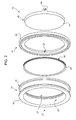
- each butterfly valve 12 comprises a supporting ring 18, defined by two coupled annular elements 19 and 20, a sealing ring 22 and a disc 23.
- the supporting ring 18 has an outer perimeter edge 24 and an inner perimeter edge 25, which defines a fluid flow section 27.
- the fluid is air from the compressor 2 flowing in a direction D (indicated in the appended figure by an arrow).
- annular elements 19 and 20 are shaped and coupled to one another so as to create an annular seat 29 arranged along the inner perimeter edge 25 of the supporting ring 18 and adapted to be engaged by the sealing ring 22.
- the annular seat 29 is defined by a first and a second annular side face 31a and 31b, which extend in radial direction and are opposite to one another and an annular bottom surface 32.
- the radial length of the first annular side face 31a is shorter than the radial length of the second annular side face 31b.
- the sealing ring 22 is partially housed in the annular seat 29 and comprises an inner annular portion 34, which is contained in the annular seat 29, and a projecting annular portion 35, which protrude in radial direction from the annular seat 29.
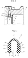
- projecting annular portion 35 means the portion of sealing ring 22 which projects with respect to the first side face 31a (as shown by the dashed line in figure 4 ).
- the sealing ring 22 has a cross section which is substantially "U” shaped so as to define an open annular cavity 38, which extends inside the inner annular portion 34 and the projecting annular portion 35.
- the cross section of the sealing ring 22 comprises two parallel arms 36 and a curved portion 37.
- Each arm 36 is defined by a flat inner face 39, by a flat base face 40 and by an outer face 41 comprising a flat central portion 43 parallel to the inner face 39 and two convex lateral portions 44.
- the flat central portions 43 are arranged in use in contact with respective annular first and second annular side faces 31a and 31b of the annular seat 29.
- the flat central portions 43 are parallel to the annular side faces 31a and 31b of the annular seat 29 so that, in use, there is a substantially uniform contact between the sealing ring 22 and the annular seat 29 to guarantee an optimal sealing and prevent the flow of fluid.
- the convex lateral portions 44 avoid the present of sharp edges and thus avoid the sealing ring 22 from penetrating in the annular seat 29 in the contact points following the thermal distortions and the pushing actions which occur during use.
- the curved portion 37 of the cross section of the sealing ring 22 is comprised in the projecting annular portion 35 and, in use, abuttingly cooperates against the disc 23 when, as will be described in greater detail below, the disc 23 is in the valve closing position.
- the thickness of the curved portion 37 is such to confer a radial flexibility to the curved portion 37 sufficient to guarantee an optimal tightness between disc 23 and sealing ring 22.
- the curved portion 37 has a thickness lower than the greater thickness of the arms 36.
- the annular cavity 38 confers elasticity and flexibility to the sealing ring 22, which can radially deform to guarantee the tightness and, at the same time, to avoid jamming between disc 23 and sealing ring 22.
- the material with which the sealing ring 22 is made is a material having the same thermal expansion coefficient as the disc 23. In this manner, the risk of jamming between disc 23 and sealing ring 22 is reduced in case of strong thermal stress.
- the disc 23 is hinged to the support ring 18, in particular to the annular element 20, and has a diameter substantially equal to the diameter of the inner perimeter edge 25 of the supporting ring 18.
- the disc 23 has a perimeter edge 45 and is provided, along the perimeter edge 45, with two eyelets 46 arranged diametrically opposite and adapted to be engaged by a pin (not shown in the appended figures) fixed to two holes 47 (only one of which is visible in figure 2 ) of the annular element 20 of the supporting ring 18.
- the disc 23 turns about the pin between a valve closing position (shown in figure 3 ), in which the disc 23 obstructs the flow section 27 and cooperates with the sealing ring 22 and a valve opening position, in which the disc 23 does not obstruct the flow section 27 allowing the flow of fluid.
- a valve closing position shown in figure 3
- the perimeter edge 45 of the disc 23 is abuttingly arranged against the projecting portion 35 of the sealing ring 22.
Landscapes
- Engineering & Computer Science (AREA)
- General Engineering & Computer Science (AREA)
- Mechanical Engineering (AREA)
- Chemical & Material Sciences (AREA)
- Combustion & Propulsion (AREA)
- Lift Valve (AREA)
Applications Claiming Priority (1)
| Application Number | Priority Date | Filing Date | Title |
|---|---|---|---|
| IT001345A ITMI20091345A1 (it) | 2009-07-29 | 2009-07-29 | Valvola a farfalla, preferibilmente per un circuito di sfiato di un impianto a turbina a gas |
Publications (1)
| Publication Number | Publication Date |
|---|---|
| EP2295836A1 true EP2295836A1 (fr) | 2011-03-16 |
Family
ID=41684205
Family Applications (1)
| Application Number | Title | Priority Date | Filing Date |
|---|---|---|---|
| EP10171142A Withdrawn EP2295836A1 (fr) | 2009-07-29 | 2010-07-28 | Vanne à papillon, particulierement pour un circuit de échappement d'une turbine à gas |
Country Status (3)
| Country | Link |
|---|---|
| US (1) | US20110024661A1 (fr) |
| EP (1) | EP2295836A1 (fr) |
| IT (1) | ITMI20091345A1 (fr) |
Families Citing this family (3)
| Publication number | Priority date | Publication date | Assignee | Title |
|---|---|---|---|---|
| CN113864468A (zh) * | 2021-10-13 | 2021-12-31 | 上海一核阀门股份有限公司 | 一种u型圈金属密封蝶阀及其制备方法 |
| CN114060541A (zh) * | 2021-12-09 | 2022-02-18 | 上海美科阀门有限公司 | 阀体及具有其的蝶阀 |
| CN116838801A (zh) * | 2023-06-16 | 2023-10-03 | 电建阀门集团有限公司 | 一种弹性金属密封环及蝶阀 |
Citations (5)
| Publication number | Priority date | Publication date | Assignee | Title |
|---|---|---|---|---|
| FR1181609A (fr) * | 1957-08-23 | 1959-06-17 | Vanne-papillon | |
| LU39860A1 (fr) * | 1960-07-18 | 1961-05-06 | ||
| US3030066A (en) * | 1957-10-24 | 1962-04-17 | David F Wiseman & Sons Ltd | Butterfly valves |
| US3080145A (en) * | 1957-10-24 | 1963-03-05 | David F Wiseman & Sons Ltd | Butterfly valves |
| US3544066A (en) * | 1967-01-03 | 1970-12-01 | Pratt Co Henry | Valve seat structure |
Family Cites Families (11)
| Publication number | Priority date | Publication date | Assignee | Title |
|---|---|---|---|---|
| US3612483A (en) * | 1968-04-12 | 1971-10-12 | Rockwell Mfg Co | Valves with deformable sealing |
| US3986699A (en) * | 1974-07-02 | 1976-10-19 | Posi-Seal International, Inc. | Positive shut-off seal |
| FI54536C (fi) * | 1975-04-15 | 1978-12-11 | Neles Oy | Klaffventil |
| US4034959A (en) * | 1975-12-24 | 1977-07-12 | Acf Industries, Incorporated | Valve seal retaining means |
| US4037819A (en) * | 1976-03-03 | 1977-07-26 | Kamyr Valves Inc. | Butterfly valve having metal-to-metal sealing with conical angle-transported vane |
| US4540457A (en) * | 1983-03-09 | 1985-09-10 | Lavalley Industrial Plastics, Inc. | Butterfly valve with pressurized O-ring sale |
| FR2559232B1 (fr) * | 1984-02-03 | 1986-08-22 | Marine Ind Petrole | Vanne a papillon spherique |
| CH674557A5 (fr) * | 1987-08-17 | 1990-06-15 | Fischer Ag Georg | |
| US5294091A (en) * | 1989-10-06 | 1994-03-15 | Keystone International Holdings Corp. | Stop cock for a liquid container |
| US6029949A (en) * | 1995-04-17 | 2000-02-29 | Flowserve Corporation | High performance butterfly valve |
| JPH1026235A (ja) * | 1996-07-12 | 1998-01-27 | Kubota Corp | バタフライ弁 |
-
2009
- 2009-07-29 IT IT001345A patent/ITMI20091345A1/it unknown
-
2010
- 2010-07-28 EP EP10171142A patent/EP2295836A1/fr not_active Withdrawn
- 2010-07-29 US US12/845,834 patent/US20110024661A1/en not_active Abandoned
Patent Citations (5)
| Publication number | Priority date | Publication date | Assignee | Title |
|---|---|---|---|---|
| FR1181609A (fr) * | 1957-08-23 | 1959-06-17 | Vanne-papillon | |
| US3030066A (en) * | 1957-10-24 | 1962-04-17 | David F Wiseman & Sons Ltd | Butterfly valves |
| US3080145A (en) * | 1957-10-24 | 1963-03-05 | David F Wiseman & Sons Ltd | Butterfly valves |
| LU39860A1 (fr) * | 1960-07-18 | 1961-05-06 | ||
| US3544066A (en) * | 1967-01-03 | 1970-12-01 | Pratt Co Henry | Valve seat structure |
Also Published As
| Publication number | Publication date |
|---|---|
| US20110024661A1 (en) | 2011-02-03 |
| ITMI20091345A1 (it) | 2011-01-30 |
Similar Documents
| Publication | Publication Date | Title |
|---|---|---|
| US7972105B2 (en) | Turbine anti-rotating stall schedule | |
| US8567184B2 (en) | Energy recovery system in a gas compression plant | |
| US8714906B2 (en) | Method and apparatus for gas turbine engine temperature management | |
| US4808069A (en) | Anti-rotation guide vane bushing | |
| US8549865B2 (en) | Pressure-actuated plug | |
| EP2295836A1 (fr) | Vanne à papillon, particulierement pour un circuit de échappement d'une turbine à gas | |
| CN102046923B (zh) | 包括耐磨塞的涡轮机转子和耐磨塞 | |
| WO2008111957A3 (fr) | Ensemble de stator comportant des orifices de prélèvement destiné à un compresseur de moteur de turbine | |
| US8911212B2 (en) | Turbomachine rotor with anti-wear shim between a disk and an annulus | |
| JP2013532795A (ja) | 高圧圧縮系での封止ガス消耗の削減および調定圧力低減のための方法及びシステム | |
| US9512724B2 (en) | Method for repairing wear marks on a rotor supporting the fan of a bypass engine | |
| EP1323892B1 (fr) | Turbine ayant un dispositif auxiliaire d'étanchéité pour des éléments statoriques et son procédé d'installation | |
| US10648356B2 (en) | Bypass turbomachine fitted with bleed system | |
| CN101169137A (zh) | 不对称的压缩机抽气方法 | |
| EP2636852B1 (fr) | Joint d'air interne hybride pour moteurs à turbine à gaz | |
| US11365678B2 (en) | Self modulating valve | |
| EP1744034A3 (fr) | Arrangement d'étanchéité pour une turbine à gaz refroidie par vapeur | |
| JP6318003B2 (ja) | フート弁 | |
| US20180313231A1 (en) | Exhaust diffuser having ejection hole and suction hole, and gas turbine having the same | |
| US20170030267A1 (en) | Sealing arrangement for gas turbine transition pieces | |
| CN104455499A (zh) | 组合密封截止阀 | |
| EP1369592B1 (fr) | Appareil d'extraction de gaz pour compresseur axial | |
| KR101243393B1 (ko) | 터보압축기를 변경하는 방법 | |
| KR200476332Y1 (ko) | 터빈 밸브 스템 정비 가이드 슬리브 | |
| JP2013189978A (ja) | 蒸気タービン及び蒸気タービンから水分を除去する方法 |
Legal Events
| Date | Code | Title | Description |
|---|---|---|---|
| PUAI | Public reference made under article 153(3) epc to a published international application that has entered the european phase |
Free format text: ORIGINAL CODE: 0009012 |
|
| AK | Designated contracting states |
Kind code of ref document: A1 Designated state(s): AL AT BE BG CH CY CZ DE DK EE ES FI FR GB GR HR HU IE IS IT LI LT LU LV MC MK MT NL NO PL PT RO SE SI SK SM TR |
|
| AX | Request for extension of the european patent |
Extension state: BA ME RS |
|
| 17P | Request for examination filed |
Effective date: 20110916 |
|
| STAA | Information on the status of an ep patent application or granted ep patent |
Free format text: STATUS: THE APPLICATION IS DEEMED TO BE WITHDRAWN |
|
| 18D | Application deemed to be withdrawn |
Effective date: 20130201 |