EP2295838A1 - Intelligente thermostatische wasserausgabevorrichtung - Google Patents
Intelligente thermostatische wasserausgabevorrichtung Download PDFInfo
- Publication number
- EP2295838A1 EP2295838A1 EP10752261A EP10752261A EP2295838A1 EP 2295838 A1 EP2295838 A1 EP 2295838A1 EP 10752261 A EP10752261 A EP 10752261A EP 10752261 A EP10752261 A EP 10752261A EP 2295838 A1 EP2295838 A1 EP 2295838A1
- Authority
- EP
- European Patent Office
- Prior art keywords
- water
- outflowing
- control circuit
- valve core
- passage
- Prior art date
- Legal status (The legal status is an assumption and is not a legal conclusion. Google has not performed a legal analysis and makes no representation as to the accuracy of the status listed.)
- Withdrawn
Links
Images


Classifications
-
- G—PHYSICS
- G05—CONTROLLING; REGULATING
- G05D—SYSTEMS FOR CONTROLLING OR REGULATING NON-ELECTRIC VARIABLES
- G05D23/00—Control of temperature
- G05D23/01—Control of temperature without auxiliary power
- G05D23/13—Control of temperature without auxiliary power by varying the mixing ratio of two fluids having different temperatures
- G05D23/1393—Control of temperature without auxiliary power by varying the mixing ratio of two fluids having different temperatures characterised by the use of electric means
-
- F—MECHANICAL ENGINEERING; LIGHTING; HEATING; WEAPONS; BLASTING
- F16—ENGINEERING ELEMENTS AND UNITS; GENERAL MEASURES FOR PRODUCING AND MAINTAINING EFFECTIVE FUNCTIONING OF MACHINES OR INSTALLATIONS; THERMAL INSULATION IN GENERAL
- F16K—VALVES; TAPS; COCKS; ACTUATING-FLOATS; DEVICES FOR VENTING OR AERATING
- F16K11/00—Multiple-way valves, e.g. mixing valves; Pipe fittings incorporating such valves
- F16K11/02—Multiple-way valves, e.g. mixing valves; Pipe fittings incorporating such valves with all movable sealing faces moving as one unit
- F16K11/06—Multiple-way valves, e.g. mixing valves; Pipe fittings incorporating such valves with all movable sealing faces moving as one unit comprising only sliding valves, i.e. sliding closure elements
- F16K11/072—Multiple-way valves, e.g. mixing valves; Pipe fittings incorporating such valves with all movable sealing faces moving as one unit comprising only sliding valves, i.e. sliding closure elements with pivoted closure members
- F16K11/074—Multiple-way valves, e.g. mixing valves; Pipe fittings incorporating such valves with all movable sealing faces moving as one unit comprising only sliding valves, i.e. sliding closure elements with pivoted closure members with flat sealing faces
- F16K11/0743—Multiple-way valves, e.g. mixing valves; Pipe fittings incorporating such valves with all movable sealing faces moving as one unit comprising only sliding valves, i.e. sliding closure elements with pivoted closure members with flat sealing faces with both the supply and the discharge passages being on one side of the closure plates
-
- F—MECHANICAL ENGINEERING; LIGHTING; HEATING; WEAPONS; BLASTING
- F16—ENGINEERING ELEMENTS AND UNITS; GENERAL MEASURES FOR PRODUCING AND MAINTAINING EFFECTIVE FUNCTIONING OF MACHINES OR INSTALLATIONS; THERMAL INSULATION IN GENERAL
- F16K—VALVES; TAPS; COCKS; ACTUATING-FLOATS; DEVICES FOR VENTING OR AERATING
- F16K31/00—Actuating devices; Operating means; Releasing devices
- F16K31/02—Actuating devices; Operating means; Releasing devices electric; magnetic
- F16K31/04—Actuating devices; Operating means; Releasing devices electric; magnetic using a motor
- F16K31/041—Actuating devices; Operating means; Releasing devices electric; magnetic using a motor for rotating valves
- F16K31/042—Actuating devices; Operating means; Releasing devices electric; magnetic using a motor for rotating valves with electric means, e.g. for controlling the motor or a clutch between the valve and the motor
-
- E—FIXED CONSTRUCTIONS
- E03—WATER SUPPLY; SEWERAGE
- E03C—DOMESTIC PLUMBING INSTALLATIONS FOR FRESH WATER OR WASTE WATER; SINKS
- E03C1/00—Domestic plumbing installations for fresh water or waste water; Sinks
- E03C1/02—Plumbing installations for fresh water
- E03C1/04—Water-basin installations specially adapted to wash-basins or baths
- E03C2001/0418—Water-basin installations specially adapted to wash-basins or baths having temperature indicating means
-
- Y—GENERAL TAGGING OF NEW TECHNOLOGICAL DEVELOPMENTS; GENERAL TAGGING OF CROSS-SECTIONAL TECHNOLOGIES SPANNING OVER SEVERAL SECTIONS OF THE IPC; TECHNICAL SUBJECTS COVERED BY FORMER USPC CROSS-REFERENCE ART COLLECTIONS [XRACs] AND DIGESTS
- Y10—TECHNICAL SUBJECTS COVERED BY FORMER USPC
- Y10T—TECHNICAL SUBJECTS COVERED BY FORMER US CLASSIFICATION
- Y10T137/00—Fluid handling
- Y10T137/7722—Line condition change responsive valves
- Y10T137/7737—Thermal responsive
-
- Y—GENERAL TAGGING OF NEW TECHNOLOGICAL DEVELOPMENTS; GENERAL TAGGING OF CROSS-SECTIONAL TECHNOLOGIES SPANNING OVER SEVERAL SECTIONS OF THE IPC; TECHNICAL SUBJECTS COVERED BY FORMER USPC CROSS-REFERENCE ART COLLECTIONS [XRACs] AND DIGESTS
- Y10—TECHNICAL SUBJECTS COVERED BY FORMER USPC
- Y10T—TECHNICAL SUBJECTS COVERED BY FORMER US CLASSIFICATION
- Y10T137/00—Fluid handling
- Y10T137/8593—Systems
- Y10T137/86493—Multi-way valve unit
- Y10T137/86815—Multiple inlet with single outlet
- Y10T137/86823—Rotary valve
Definitions
- the present invention relates to a water outflowing device, in particular, to an intelligent thermostatic water outflowing device in the field of sanitary wares.
- the conventional water outflowing devices of sanitary products could not meet the demands of these people.
- the water outflowing devices of sanitary products particularly the water outlflowing devices in which the water temperature could be adjusted, have the defects as mentioned hereinafter.
- the adjusting of the outflowing water temperature could not be accomplished on demands, and the immediacy of the water temperature adjusting is not so ideal that the users have to make adjustments according to the actual outflowing water temperature.
- the automatic thermostatic adjusting process could not be accomplished, in which case the users have to make manual adjustments.
- the outflowing water could not be automatically shut off when the use is finished, and the device could not be automatically arranged in the outflowing water temperature state set last time or in the outflowing water temperature state newly set when the device is turned on again.
- the Chinese Patent Application No. 200810061571 discloses an intelligent thermostatic valve having a valve body and a valve core, in which the inner cavity of the valve body is divided into a hot water cavity, a mixing water cavity and a cold water cavity in sequence.
- a hot water inlet, a warm water outlet, a cold water inlet and a cold water outlet are provided on the valve body.
- the warm water outlet is equipped with a warm water outlet nipple and the cold water inlet is equipped with a cold water inlet nipple.
- Valve ports are placed on both ends of the mixing water cavity.
- the valve core could be mounted within the mixing water cavity in such a way that it could move to and fro along the axial direction of the mixing water cavity.
- the plugs at both ends of the valve core are adapted with the valve ports at both ends of the mixing water cavity respectively, so as to control the ratio of cold water and hot water flowing into the mixing water cavity.
- One end of the valve core is connected with a linear step motor external to the valve body via a motor shaft.
- a warm water temperature sensor is mounted within the warm water outlet nipple.
- An inflowing water flow meter and an inflowing water flow sensor matched therewith are mounted within the cold water inlet nipple.
- the outflowing water temperature could be automatically adjusted by using the aforementioned solution, but the whole structure of the device is relatively complicated and both a warm water temperature sensor and a water flow sensor have to be provided, bringing about a higher cost.
- the linear step motor is used to control the valve core to move in an axial direction to accomplish adjusting the temperature in this solution, which could only adjust the water temperature but could not turn on or shut off the outflowing water. Therefore, the solution could only be applied to adjust the water temperature in the pipes but could not be applicable to the ordinary valves.
- the present invention provides an intelligent thermostatic water outflowing device, comprising a body provided with a hot water inflowing passage, a cold water inflowing passage and a water outflowing passage, and a valve core assembly provided between the cold water inflowing passage, the hot water inflowing passage and the water outflowing passage within the body.
- the present device further includes a motor, a water temperature control circuit and a temperature sensor.
- the valve core rod of the valve core assembly is connected with the output shaft of the motor fixed within the body.
- the temperature sensor is placed in the water outflowing passage and connected with the water temperature control circuit.
- the water temperature control circuit is connected with the motor and has an external power source connected thereto for supplying the power. The operation of the motor could be controlled by the water temperature control circuit according to the outflowing water temperature detected by the temperature sensor.
- the external power source could supply power for the water temperature control circuit, so that the operation of the motor could be controlled by the water temperature control circuit. Since the rotating shaft of the motor is connected with the valve core rod of the valve core assembly, the valve core assembly could adjust the ratio of the outflowing cold water and hot water when the valve core rod is driven to rotate by the rotating shaft of the motor, thus the outflowing water temperature could be adjusted. When the outflowing water temperature is determined, it would be brought to vary due to the difference in water pressures in the hot water inflowing passage and the cold water inflowing passage, the water temperature variances of the hot water inflowing passage and the cold water inflowing passage, and the like.
- the temperature sensor could detect the water temperature variances of the water outflowing passage in time, and control the operation of the motor with the water temperature control circuit, thereby accomplishing adjusting the water temperature in time. Therefore, the outflowing water temperature from the water outflowing passage could be kept constant.
- the device further includes a power generator fixed in the water outflowing passage.
- An impeller is fixed on the rotating shaft of the power generator.
- the power generator is directly connected with the water temperature control circuit or connected with the water temperature control circuit via a storage battery.
- the water temperature control circuit could disconnect the external power source from the water temperature control circuit when the power generator is in operation and/or the storage battery has power.
- the water temperature control circuit could not control the operation of the motor as no power is supplied thereto. In this case, there is a need for an external power source to continually supply power for the water temperature control circuit.
- the storage battery or the power generator could supply power for the water temperature control circuit, thereby controlling the operation of the motor in accordance with the water temperature states. In this respect, the operation of the motor could be controlled by the water temperature control circuit even without the external power source.
- the water temperature control circuit could be supplied with power mainly in the following manners.
- the external power source would continually supply power for the water temperature control circuit to facilitate the operation of the motor.
- the external power source supplies power for the water temperate control circuit only when the power generator is out of operation during starting the whole device.
- the external power source supplies power for the water temperate control circuit only when the storage battery does not have any power and the power generator is out of operation during starting the whole device.
- the water temperature control circuit is connected with a control panel fixed on the body.
- a switch button is provided on the control panel for turning on or off the motor and a temperature adjusting button is further provided on the control panel for adjusting the water temperature.
- the valve core assembly is set in the outflowing water cut-off status when the switch button is in the off status.
- the outflowing water temperature could be conveniently preset before the water is flown out, and the outflowing water temperature could be adjusted in time during the operation.
- the intelligent thermostatic water outflowing device could be turned on or off with the switch button.
- the switch button When the switch button is in the off status, the valve core assembly is driven by the motor to reset, so that the valve core assembly is in the outflowing water cut-off status; and when the switch button is in the on status, the valve core assembly is driven by the motor to be adjusted to the preset water temperature state.
- the valve core assembly first communicates the cold water inflowing passage with the outflowing passage as soon as the switch button is pressed, so as to prevent the high temperature stream being flown out in the initial state, thereby improving the use safety.
- the water temperature control circuit is a printed circuit board having a chip, and the water temperature control circuit is further connected with a temperature display which is fixed on the control panel.
- the set outflowing water temperature could be understood with the temperature display in an expedient way. This way, the user could immediately determine the water temperature and make corresponding adjustments.
- the valve core assembly includes a static porcelain piece fixed within the body and a movable porcelain piece which could rotate relative to the static porcelain piece.
- a cold water inflowing hole, a hot water inflowing hole and a water outflowing hole are positioned on the static porcelain piece for communicating with the cold water inflowing passage, the hot water inflowing passage and the water outflowing passage respectively.
- the movable porcelain piece is fixedly connected with the valve core rod and could communicate the water outflowing hole of the static porcelain piece with the cold water inflowing hole and/or the hot water inflowing hole.
- the cold water flows out of the water outflowing passage.
- the movable porcelain piece communicates the water outflowing hole with both the cold water inflowing hole and the hot water inflowing hole, warm water mixed by the hot water and the cold water flows out of the water outflowing passage, in which case the water temperature could be adjusted by conditioning the ratio of outflowing cold water and hot water.
- the hot water flows out of the water outflowing passage.
- a valve core cover is fixed within the body.
- One end of the valve core rod is passed through the valve core cover and a connecting hole is set at the end of the valve core rod.
- the motor is fixed on the valve core cover and a gear is connected with the output shaft of the motor.
- the connecting hole has a configuration matched with the outline of the gear provided on the inner wall thereof and the gear is inserted in the connecting hole.
- the motor is a step motor. Said motor and water temperature control circuit are disposed at the same side of the valve core cover within the body. The other side of the valve core cover is fixedly connected with the valve core seat. The static porcelain piece, the movable porcelain piece and the valve core rod are mounted within the valve core seat.
- the step motor could guarantee the reliability and precision in adjusting the water temperature.
- the motor and the water temperature control circuit are disposed at the same side of the valve core cover so that the stream could be prevented from affecting the operation thereof. Thus, the operation reliability is enhanced.
- the motor is a deceleration step motor or a deceleration mechanism is provided between the output shaft of the motor and the gear. Such a configuration could efficiently improve the precision in adjusting the water temperature.
- the device includes an illumination control circuit and an illuminator fixed at the water outlet of the water outflowing passage.
- the illumination control circuit is connected with the power generator and the temperature sensor respectively.
- the illuminator is connected with the illumination control circuit and the illumination control circuit could control the illuminator to emit lights of different colors with respect to different temperature ranges of the outflowing water detected by the temperature sensor when the impeller is driven to rotate by the stream and the power generator is thus operated.
- the stream could drive the impeller to rotate when it passes the water outflowing passage, so that the power generator will be put in operation and generate the power.
- the energy could be saved, and an additional illuminator control switch is not required since the power source would automatically shut off when there exists no stream.
- the temperature sensor would transmit the outflowing water temperature detected to the illumination control circuit, and the illumination control circuit could control the operation of the illuminator according to the signal from the temperature sensor. In this case, the user could visually perceive the water temperature states in accordance with the lights of different colors in a convenient way and would not be subject to scalding or cool irritation.
- the corresponding relation between the temperature ranges of the outflowing water and the colors of the lights could be set to demands.
- the lights emitted by the illuminator could be seen by the user with the stream, which not only increases the visual effects, but also performs an auxiliary illuminating function, thereby providing a very convenient use.
- the illumination control circuit could be integrated with the water temperature control circuit on one circuit board.
- the temperature sensor could provide a water temperature signal for the water temperature control circuit and the illumination control circuit at the same time.
- a bubbler is fixed at the water outlet of the water outflowing passage.
- the bubbler includes a central seat having a through hole and a mounting seat set around the central seat.
- the central seat is integrated with the mounting seat and several water-air mixing holes are evenly distributed on the side wall of the central seat.
- the illuminator is a multi-color LED light which could emit lights of a plurality of colors and is inserted in the through hole. Several diversion posts are evenly distributed at the side of the water-air mixing holes within the central seat.
- the illuminator could be readily mounted within the water outflowing passage with the bubbler. Moreover, the bubbler could produce a lot of bubbles when the stream passes through the bubbler. When the lights irradiate the stream mixed with bubbles, the lights mixed in the stream would become softer and more aesthetic by using a plurality of light broadcasting means, such as total reflection, reflection, scattering, refraction, convergence and interference of lights. In addition, the illuminator would not affect the normal operation of the bubbler when it is inserted in the bubbler, but makes the light sources in the center, thereby providing a better light broadcasting effect.
- the bubbling effect would be efficiently increased as the stream and air come into the bubbler from the side.
- the diversion posts could make the stream uniformly flow to the water-air mixing holes, which produces a better bubbling effect.
- the intelligent thermostatic water outflowing device has the following advantages over the prior art.
- the outflowing water temperature could be preset. Since the sensor could detect the outflowing water temperature real time, the valve core assembly could be controlled by the motor when the water temperature varies. Therefore, the ratio of the outflowing cold water and hot water could be adjusted to achieve the purpose of providing thermostatic outflowing water. Besides, a high control precision could be obtained by the device.
- valve core assembly is set in the outflowing water cut-off status when the switch button is in the off status, and thus the water outflowing device could be automatically shut off or turned on. Moreover, the valve core assembly firstly communicates the cold water inflowing passage with the water outflowing passage during starting the valve core assembly, in which case the high temperature stream would not flow out in the initial state, thereby improving the use safety.
- the user would be noticed of the outflowing water temperature with the prompting lights, and thus would not be subject to scalding or cool irritation.
- the stream flown out is mixed with the lights to produce a good visual effect and increase the sentiment in use.
- the water temperature could be preset and adjusted, and the valve core assembly could be reset by supplying power for the water temperature control circuit with, for example, the external power source, the power generator and the storage battery.
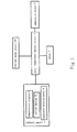
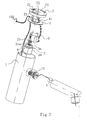
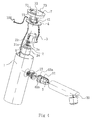
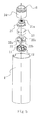
- the intelligent thermostatic water outflowing device comprises a body 1, a valve core assembly 2, a motor 3, a water temperature control circuit 4, a temperature sensor 5, an external power source 100, a control panel 7, and so on.
- the body 1 is provided with a hot water inflowing passage 12, a cold water inflowing passage 11 and a water outflowing passage 13.
- a valve core assembly 2 is provided between the cold water inflowing passage 11, the hot water inflowing passage 12 and the water outflowing passage 13 within the body 1.
- the valve core rod 21 of the valve core assembly 2 is connected with the output shaft of the motor 3 fixed within the body 1.
- the temperature sensor 5 is placed in the water outflowing passage 13 and connected with the water temperature control circuit 4.
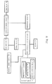
- the water temperature control circuit 4 is connected with the motor 3 and has an external power source 100 connected thereto for supplying the power. The operation of the motor 3 could be controlled by the water temperature control circuit 4 according to the outflowing water temperature detected by the temperature sensor 5.
- the water temperature control circuit 4 is connected with a control panel 7 fixed on the body 1.
- a switch button 72 is provided on the control panel 7 for turning on or off the motor 3 and a temperature adjusting button 73 is further provided on the control panel 7 for adjusting the water temperature.
- the valve core assembly 2 is set in the outflowing water cut-off status when the switch button 72 is in the off status.
- the water temperature control circuit 4 is a printed circuit board having a chip 41.
- the water temperature control circuit 4 is further connected with a temperature display 71 which is fixed on the control panel 7.
- the valve core assembly includes a static porcelain piece 22 fixed within the body 1 and a movable porcelain piece 23 which could rotate relative to the static porcelain piece 22.
- a cold water inflowing hole 22a, a hot water inflowing hole 22b and a water outflowing hole 22c are positioned on the static porcelain piece 22 for communicating with the cold water inflowing passage 11, the hot water inflowing passage 12 and the water outflowing passage 13 respectively.
- the movable porcelain piece 23 is fixedly connected with the valve core rod 21 and could communicate the water outflowing hole 22c of the static porcelain piece 22 with the cold water inflowing hole 22a and/or the hot water inflowing hole 22b.
- a valve core cover 8 is fixed within the body 1.
- valve core rod 21 One end of the valve core rod 21 is passed through the valve core cover 8 and a connecting hole 21a is set at the end of the valve core rod 21.
- the motor 3 is fixed on the valve core cover 8 and a gear 3a is connected with the output shaft of the motor 3.
- the connecting hole 21a has a configuration matched with the outline of the gear 3a provided on the inner wall thereof and the gear 3a is inserted in the connecting hole 21a.
- the motor 3 of this embodiment is a deceleration step motor.
- Said motor 3 and water temperature control circuit 4 are disposed at the same side of the valve core cover 8 within the body 1.
- the other side of the valve core cover 8 is fixedly connected with the valve core seat 24.
- the aforementioned static porcelain piece 22, movable porcelain piece 23 and valve core rod 21 are mounted within the valve core seat 24.
- the rotation precision of the valve core rod 21 could be higher since the deceleration step motor is used, in which case the rotation angle of the valve core rod 21 each time could be 0.5 degrees in minimum.
- the temperature adjusting precision of the device is very high as the minimum rotation angle of the valve ore rod 21 could be 0.5 degrees, in which case the temperature deviation would not exceed 0.5°C.
- the external power source 100 of this embodiment continually provides power for the water temperature control circuit 4.
- the ratio of cold water to hot water in the outflowing water could be adjusted by the valve core assembly 2 when the valve core rod 21 is driven by the rotating shaft of the motor 3 to rotate, thereby accomplishing adjusting the outflowing water temperature.
- the outflowing water temperature is determined, it would be brought to vary due to the difference in water pressures in the hot water inflowing passage 12 and the cold water inflowing passage 11, the water temperature variances of the hot water inflowing passage 12 and the cold water inflowing passage 11, and the like.
- the temperature sensor 5 would detect the water temperature variances of the water outflowing passage 13 in time, and control the operation of the motor 3 with the water temperature control circuit 4, thereby accomplishing adjusting the water temperature in time. Therefore, the outflowing water temperature from the water outflowing passage 13 could be kept constant.
- the valve core assembly 2 firstly communicates the cold water inflowing passage 11 with the water outflowing passage 13 as soon as the switch button 72 is pressed down, so as to prevent the stream of a high temperature from being flown out in the initial state, in which case the use safety is enhanced.
- the intelligent thermostatic water outflowing device could be controlled to start or stop by the switch button 72.
- the switch button 72 is off, the valve core assembly 2 is brought by the motor 3 to reset, and the valve core assembly 2 is set in the outflowing water cut-off status.
- the switch button 72 is on, the valve core assembly 2 is adjusted to the status of a predetermined water temperature by the motor 3.
- the present device further includes a power generator 62 fixed in the water outflowing passage 13.
- An impeller 63 is fixed on the rotating shaft of the power generator 62.
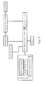
- the power generator 62 is directly connected with the water temperature control circuit 4.
- the water temperature control circuit 4 could disconnect the external power source 100 from the water temperature control circuit 4 when the power generator 62 is in operation.
- the device further includes an illumination control circuit 9 and an illuminator 10 fixed at the water outlet of the water outflowing passage 13.
- the illumination control circuit 9 is connected with the power generator 62 and the temperature sensor 5 respectively.
- the illuminator 10 is connected with the illumination control circuit 9 and the illumination control circuit 9 could control the illuminator 10 to emit lights of different colors with respect to different temperature ranges of the outflowing water detected by the temperature sensor 5 when the impeller 63 is driven to rotate by the stream and the power generator 62 is thus operated.
- a bubbler 30 is fixed at the water outlet of the water outflowing passage 13.
- the bubbler 30 includes a central seat 31 having a through hole 31a and a mounting seat 32 set around the central seat 31.
- the central seat 31 is integrated with the mounting seat 32 and several water-air mixing holes 31b are evenly distributed on the side wall of the central seat 31.
- the illuminator 10 is a multi-color LED light which could emit lights of a plurality of colors and is inserted in the through hole 31a.
- Several diversion posts 31c are evenly distributed at the side of the water-air mixing holes 31b within the central seat 31.
- the housing of the power generator 62 is enclosed.
- An annular water passing gap 14 is provided between the outer wall of the generator housing and the inner wall of the water outflowing passage 13.
- An impeller tube 63a is provided at one end of the generator housing, which is fixedly connected to the water outflowing passage 13 and set around the impeller 63.
- a diversion water through hole 63b is positioned at the connecting end of the impeller tube 63a with the generator housing for communicating with the water passing gap 14.
- the diversion water through hole 63b is uniformly positioned in a circumferential direction.
- the impeller tube 63a is firmly fitted into the water outflowing passage 13 and is integrated with the generator housing.
- the illumination control circuit 9 is enclosed within the housing of the power generator 62, and connected with the illuminator 10 out of the generator housing via the wire passing through the generator end cover of the generator housing.
- the temperature sensor 5 is sealingly fixed on the generator housing and partly extends out of the generator housing.
- the power produced by the power generator 62 could be used to supply power for the water temperature control circuit 4, so that the operation of the power generator 3 could be controlled by the water temperature control circuit 4.
- the external power source 100 supplies power for the water temperature control circuit 4 only when the power generator 52 is out of operation during starting the whole device.
- the illumination control circuit 9 could control the illuminator 10 to emit a blue light when the temperate sensor 5 detects the outflowing water temperature is lower than 30°C.
- the illumination control circuit 9 could control the illuminator 10 to emit a green light when the temperate sensor 5 detects the outflowing water temperature is within 30°C ⁇ 36°C.
- the illumination control circuit 9 could control the illuminator 10 to emit a red light when the temperate sensor 5 detects the outflowing water temperature is higher than 36°C.
- the power generator 62 is connected to the water temperature control circuit 4 via a storage battery 61.
- the external power source supplies power for the water temperature control circuit 4 only when the storage battery 61 does not have power and the power generator 62 is out of operation during starting the whole device.
- the remaining parts of this embodiment are similar to those of the second embodiment and thus not further described herein for the purpose of brevity.
- valve core assembly 2 valve core rod 21, connecting hole 21a, static porcelain piece 22, cold water inflowing hole 22a, hot water inflowing hole 22b, water outflowing hole 22c, movable porcelain piece 23, valve core seat 24, motor 3, gear 3a, water temperature control circuit 4, chip 41, temperature sensor 5, storage battery 61, power generator 62, impeller 63, impeller tube 63a, diversion water through hole 63b, water inflowing hole 63ab, control panel 7, temperature display 71, switch button 72, temperature adjusting button 73, valve core cover 8, illumination control circuit 9, illuminator 10, LED light 10a, bubbler 30, central seat 31, through hole 31a, water-air mixing hole 31b, diversion post 31c, mounting seat 32, external power source 100 and the like, other terms are not excluded being used. Said terms are merely used to describe and explain the essence of the invention more conventionally. It is in violation of the spirit of the invention to
Landscapes
- Engineering & Computer Science (AREA)
- General Engineering & Computer Science (AREA)
- Mechanical Engineering (AREA)
- Physics & Mathematics (AREA)
- General Physics & Mathematics (AREA)
- Automation & Control Theory (AREA)
- Temperature-Responsive Valves (AREA)
- Control Of Temperature (AREA)
Applications Claiming Priority (2)
| Application Number | Priority Date | Filing Date | Title |
|---|---|---|---|
| CN2009201547087U CN201434112Y (zh) | 2009-05-20 | 2009-05-20 | 智能恒温出水装置 |
| PCT/CN2010/072543 WO2010133137A1 (zh) | 2009-05-20 | 2010-05-08 | 智能恒温出水装置 |
Publications (2)
| Publication Number | Publication Date |
|---|---|
| EP2295838A1 true EP2295838A1 (de) | 2011-03-16 |
| EP2295838A4 EP2295838A4 (de) | 2014-07-09 |
Family
ID=42052920
Family Applications (1)
| Application Number | Title | Priority Date | Filing Date |
|---|---|---|---|
| EP10752261.7A Withdrawn EP2295838A4 (de) | 2009-05-20 | 2010-05-08 | Intelligente thermostatische wasserausgabevorrichtung |
Country Status (4)
| Country | Link |
|---|---|
| US (1) | US8833670B2 (de) |
| EP (1) | EP2295838A4 (de) |
| CN (1) | CN201434112Y (de) |
| WO (1) | WO2010133137A1 (de) |
Cited By (1)
| Publication number | Priority date | Publication date | Assignee | Title |
|---|---|---|---|---|
| EP3259506A1 (de) * | 2015-02-16 | 2017-12-27 | Oblamatik AG | Ventil zum steuern des wasserflusses in einer sanitärleitung |
Families Citing this family (28)
| Publication number | Priority date | Publication date | Assignee | Title |
|---|---|---|---|---|
| CN201434112Y (zh) * | 2009-05-20 | 2010-03-31 | 陈启岳 | 智能恒温出水装置 |
| CN102147022A (zh) * | 2010-12-02 | 2011-08-10 | 陈旭敏 | 智能恒温阀 |
| CN105387257B (zh) * | 2015-12-29 | 2018-09-04 | 浙江盾安自控科技有限公司 | 电动调节阀 |
| CN108953734B (zh) * | 2016-04-18 | 2019-09-24 | 宁波索顿飞羽电器有限公司 | 水流发电自动恒温控制器 |
| CN109027378B (zh) * | 2016-04-18 | 2020-11-20 | 宁波索顿飞羽电器有限公司 | 触摸式恒温水龙头系统 |
| US10036150B2 (en) * | 2016-05-31 | 2018-07-31 | Xiamen Forbetter Sanitary Ware Co., Ltd. | Automatic faucet |
| CN106015718A (zh) * | 2016-06-06 | 2016-10-12 | 淮南市鸿裕工业产品设计有限公司 | 水力控制阀热效率损耗降低控制装置 |
| CN106490991A (zh) * | 2016-12-29 | 2017-03-15 | 佛山市顺德区佑安电子有限公司 | 智能火锅内盘升降机构 |
| TWM563506U (zh) * | 2017-05-24 | 2018-07-11 | 阿格特衛浴設備(廈門)有限公司 | 水溫偵測閥 |
| TWM560545U (zh) * | 2017-05-26 | 2018-05-21 | Agreat Shower & Sanitary Xiamen Co Ltd | 水龍頭之感溫顯示裝置 |
| CN109805754A (zh) * | 2017-11-22 | 2019-05-28 | 广东美的生活电器制造有限公司 | 液体加热容器 |
| CN108061180A (zh) * | 2018-01-26 | 2018-05-22 | 新疆天脉农业智控科技有限公司 | 一种通用阀及灌溉设备 |
| US10612221B2 (en) * | 2018-04-25 | 2020-04-07 | Xiamen Forbetter Sanitary Ware Co., Ltd. | Intelligent faucet structure based on photoelectric detection device |
| CN108678089A (zh) * | 2018-06-04 | 2018-10-19 | 厦门建霖健康家居股份有限公司 | 一种具有片状水出水方式的台盆及出水装置 |
| CN108708989A (zh) * | 2018-07-26 | 2018-10-26 | 潍坊康斯拓普温控卫浴有限公司 | 一种数显恒温阀 |
| CN109199869A (zh) * | 2018-09-18 | 2019-01-15 | 张仕华 | 一种安全吸管瓶 |
| CN110410571A (zh) * | 2019-07-31 | 2019-11-05 | 深圳市鼎欣茂科技有限公司 | 一种智能恒温出水装置 |
| CN110398404B (zh) * | 2019-08-21 | 2023-12-22 | 广州耐确医疗器械有限责任公司 | 一种具有自净功能的双缸冷暖摊片机 |
| CN111043355B (zh) * | 2019-12-25 | 2020-12-29 | 浙江大学 | 温度自动控制的三通道球阀 |
| CN111035242B (zh) * | 2020-01-06 | 2024-08-09 | 小熊电器股份有限公司 | 一种出水装置及电热水瓶 |
| CN111297186A (zh) * | 2020-02-23 | 2020-06-19 | 深圳市久大轻工机械有限公司 | 自动调温智能饮水机 |
| CN112066044A (zh) * | 2020-09-02 | 2020-12-11 | 厦门方特卫浴有限公司 | 一种多控制龙头 |
| CN112833245B (zh) * | 2021-03-02 | 2025-11-11 | 厦门大白科技有限公司 | 一种用于出水终端的感应控制模组及具有其的感应龙头 |
| CN113915044B (zh) * | 2021-11-12 | 2024-11-26 | 温州美居智能科技有限公司 | 一种利用水力发电的阀芯 |
| CN114198911B (zh) * | 2021-12-02 | 2023-09-08 | 驭云(厦门)网络科技股份有限公司 | 一种基于智能感应的饮水装置 |
| CN115492964A (zh) * | 2022-09-15 | 2022-12-20 | 广东斯飞奥博泰智能卫浴科技有限公司 | 一种新型智能恒温龙头控制系统 |
| TWM638533U (zh) * | 2022-09-28 | 2023-03-11 | 訊凱國際股份有限公司 | 比例閥 |
| WO2026020489A1 (zh) * | 2024-07-26 | 2026-01-29 | 魏珍贵 | 一种多功能流量可调手持出水装置 |
Family Cites Families (17)
| Publication number | Priority date | Publication date | Assignee | Title |
|---|---|---|---|---|
| NO152880C (no) * | 1983-08-30 | 1985-12-04 | Lyng Ind As | Temperaturpaavirkbar, elektronisk styrt blandeventil for blanding av to vaesker. |
| DE4124154C2 (de) | 1991-07-20 | 1995-11-02 | Oeko Patent Finanz Ag | Sanitärarmatur |
| KR100436626B1 (ko) | 2001-09-25 | 2004-06-23 | 성 용 조 | 자동온도 조정형 수도밸브 및 그를 이용한 가정용 온천수기 |
| CN2536857Y (zh) * | 2001-11-19 | 2003-02-19 | 王冬雷 | 数码恒温混水阀 |
| US6913203B2 (en) * | 2003-12-03 | 2005-07-05 | Delangis Eric | Self powered electronically controlled mixing valve |
| CN2685676Y (zh) * | 2004-03-26 | 2005-03-16 | 曹樊德 | 数控调温水笼头 |
| CN1670411A (zh) * | 2005-03-11 | 2005-09-21 | 冷同桂 | 一种数控恒温阀 |
| US7681860B2 (en) * | 2006-09-22 | 2010-03-23 | Jorge Maercovich | Automate fluid flow control system |
| CN201014041Y (zh) * | 2007-02-09 | 2008-01-30 | 陈启岳 | 改进结构的温控水龙头 |
| CN101368646A (zh) * | 2007-08-13 | 2009-02-18 | 徐小羚 | 用水发电的温敏变色水龙头 |
| GB2452043C2 (en) * | 2007-08-21 | 2025-07-30 | Chalmor Ltd | Thermostatic control device |
| NL1035475C2 (nl) * | 2008-05-27 | 2009-11-30 | Jurgen Verwoert | Sanitaire tapkraan met generator voor elektrische energie. |
| CN101382204B (zh) * | 2008-09-19 | 2011-05-11 | 王永进 | 一种光电检测恒温控制阀 |
| CN101430013B (zh) * | 2008-11-03 | 2011-05-11 | 王晓福 | 一种双控式恒温控制器 |
| CN201434111Y (zh) * | 2009-04-23 | 2010-03-31 | 陈启岳 | 恒温出水装置 |
| CN101566253B (zh) * | 2009-04-23 | 2011-02-02 | 陈启岳 | 恒温出水装置 |
| CN201434112Y (zh) * | 2009-05-20 | 2010-03-31 | 陈启岳 | 智能恒温出水装置 |
-
2009
- 2009-05-20 CN CN2009201547087U patent/CN201434112Y/zh not_active Expired - Fee Related
-
2010
- 2010-05-08 WO PCT/CN2010/072543 patent/WO2010133137A1/zh not_active Ceased
- 2010-05-08 EP EP10752261.7A patent/EP2295838A4/de not_active Withdrawn
- 2010-05-08 US US12/936,668 patent/US8833670B2/en not_active Expired - Fee Related
Cited By (1)
| Publication number | Priority date | Publication date | Assignee | Title |
|---|---|---|---|---|
| EP3259506A1 (de) * | 2015-02-16 | 2017-12-27 | Oblamatik AG | Ventil zum steuern des wasserflusses in einer sanitärleitung |
Also Published As
| Publication number | Publication date |
|---|---|
| WO2010133137A1 (zh) | 2010-11-25 |
| US8833670B2 (en) | 2014-09-16 |
| EP2295838A4 (de) | 2014-07-09 |
| CN201434112Y (zh) | 2010-03-31 |
| US20110120574A1 (en) | 2011-05-26 |
Similar Documents
| Publication | Publication Date | Title |
|---|---|---|
| US8833670B2 (en) | Intelligent thermostatic water outflowing device | |
| EP2016233B1 (de) | Integriertes system für sanitäre hydro-thermo-vorrichtungen | |
| CN201977666U (zh) | 一种智能淋浴器 | |
| US20040032749A1 (en) | Night light for plumbing fixtures | |
| CN113349659B (zh) | 用于照明淋浴的系统和方法 | |
| EP3699365B1 (de) | Betriebsschalter vom jog-radtyp und damit versehener spülschrank | |
| US20200263400A1 (en) | User Interface for Controlling a Shower System | |
| EP2386927A2 (de) | Thermostatische Armatur | |
| US20110012356A1 (en) | Generator | |
| EP2264252A1 (de) | Armaturvorrichtung | |
| CA3096019A1 (en) | Electronic faucet | |
| EP3739247B1 (de) | Hahn zur abgabe von ozonisiertem wasser | |
| US11834814B2 (en) | Device for a shower, consisting of a housing, a temperature controller, an LCD screen, a LED ring, two opening taps; a hot and cold water inlet; a three-way valve, a flowmeter connected to a pump; a thermostatic valve, a servomotor; and an integrated circuit card; method | |
| US10466725B2 (en) | Device for controlling water heater | |
| EP3029208B1 (de) | Elektronisches steuerungssystem für eine duschanlage | |
| US20080271795A1 (en) | Process and Device for Producing Colored Streams of Fluid for a Hot Water Fitting | |
| CN205155161U (zh) | 一种智能水龙头温度控制装置 | |
| CN209671737U (zh) | 一种机电一体温度显示龙头 | |
| KR20130103976A (ko) | 저장식 전기온수기 | |
| CN101576285B (zh) | 智能供水中央处理器 | |
| JP2002364035A (ja) | 浴室用水栓装置 | |
| KR200376769Y1 (ko) | 수온감응 발광 샤워헤드 | |
| CN208098416U (zh) | 一种气液混合装置及花洒 | |
| CN205165011U (zh) | 一种整体式花洒 | |
| CN208098415U (zh) | 一种花洒发光组件及花洒 |
Legal Events
| Date | Code | Title | Description |
|---|---|---|---|
| PUAI | Public reference made under article 153(3) epc to a published international application that has entered the european phase |
Free format text: ORIGINAL CODE: 0009012 |
|
| 17P | Request for examination filed |
Effective date: 20100920 |
|
| AK | Designated contracting states |
Kind code of ref document: A1 Designated state(s): AL AT BE BG CH CY CZ DE DK EE ES FI FR GB GR HR HU IE IS IT LI LT LU LV MC MK MT NL NO PL PT RO SE SI SK SM TR |
|
| AX | Request for extension of the european patent |
Extension state: BA ME RS |
|
| DAX | Request for extension of the european patent (deleted) | ||
| A4 | Supplementary search report drawn up and despatched |
Effective date: 20140610 |
|
| RIC1 | Information provided on ipc code assigned before grant |
Ipc: G05D 23/13 20060101ALI20140602BHEP Ipc: F16K 51/00 20060101ALI20140602BHEP Ipc: F16K 31/53 20060101ALI20140602BHEP Ipc: F16K 11/06 20060101ALI20140602BHEP Ipc: F16K 11/02 20060101ALI20140602BHEP Ipc: F16K 37/00 20060101ALI20140602BHEP Ipc: F16K 31/04 20060101ALI20140602BHEP Ipc: F16K 31/64 20060101AFI20140602BHEP |
|
| RIC1 | Information provided on ipc code assigned before grant |
Ipc: F16K 11/074 20060101AFI20160629BHEP Ipc: E03C 1/04 20060101ALI20160629BHEP Ipc: F16K 31/04 20060101ALI20160629BHEP Ipc: G05D 23/13 20060101ALI20160629BHEP |
|
| STAA | Information on the status of an ep patent application or granted ep patent |
Free format text: STATUS: THE APPLICATION IS DEEMED TO BE WITHDRAWN |
|
| 18D | Application deemed to be withdrawn |
Effective date: 20161201 |