EP2295860A2 - Aerodynamisches Pylonbrennstoffeinspritzsystem für Brennkammern - Google Patents
Aerodynamisches Pylonbrennstoffeinspritzsystem für Brennkammern Download PDFInfo
- Publication number
- EP2295860A2 EP2295860A2 EP10171758A EP10171758A EP2295860A2 EP 2295860 A2 EP2295860 A2 EP 2295860A2 EP 10171758 A EP10171758 A EP 10171758A EP 10171758 A EP10171758 A EP 10171758A EP 2295860 A2 EP2295860 A2 EP 2295860A2
- Authority
- EP
- European Patent Office
- Prior art keywords
- fuel injection
- combustor
- radial
- turbine
- elements
- Prior art date
- Legal status (The legal status is an assumption and is not a legal conclusion. Google has not performed a legal analysis and makes no representation as to the accuracy of the status listed.)
- Withdrawn
Links
Images
Classifications
-
- F—MECHANICAL ENGINEERING; LIGHTING; HEATING; WEAPONS; BLASTING
- F23—COMBUSTION APPARATUS; COMBUSTION PROCESSES
- F23R—GENERATING COMBUSTION PRODUCTS OF HIGH PRESSURE OR HIGH VELOCITY, e.g. GAS-TURBINE COMBUSTION CHAMBERS
- F23R3/00—Continuous combustion chambers using liquid or gaseous fuel
- F23R3/28—Continuous combustion chambers using liquid or gaseous fuel characterised by the fuel supply
- F23R3/286—Continuous combustion chambers using liquid or gaseous fuel characterised by the fuel supply having fuel-air premixing devices
-
- F—MECHANICAL ENGINEERING; LIGHTING; HEATING; WEAPONS; BLASTING
- F23—COMBUSTION APPARATUS; COMBUSTION PROCESSES
- F23D—BURNERS
- F23D14/00—Burners for combustion of a gas, e.g. of a gas stored under pressure as a liquid
- F23D14/46—Details
- F23D14/62—Mixing devices; Mixing tubes
- F23D14/64—Mixing devices; Mixing tubes with injectors
-
- F—MECHANICAL ENGINEERING; LIGHTING; HEATING; WEAPONS; BLASTING
- F23—COMBUSTION APPARATUS; COMBUSTION PROCESSES
- F23R—GENERATING COMBUSTION PRODUCTS OF HIGH PRESSURE OR HIGH VELOCITY, e.g. GAS-TURBINE COMBUSTION CHAMBERS
- F23R3/00—Continuous combustion chambers using liquid or gaseous fuel
- F23R3/02—Continuous combustion chambers using liquid or gaseous fuel characterised by the air-flow or gas-flow configuration
- F23R3/16—Continuous combustion chambers using liquid or gaseous fuel characterised by the air-flow or gas-flow configuration with devices inside the flame tube or the combustion chamber to influence the air or gas flow
- F23R3/18—Flame stabilising means, e.g. flame holders for after-burners of jet-propulsion plants
- F23R3/20—Flame stabilising means, e.g. flame holders for after-burners of jet-propulsion plants incorporating fuel injection means
-
- F—MECHANICAL ENGINEERING; LIGHTING; HEATING; WEAPONS; BLASTING
- F23—COMBUSTION APPARATUS; COMBUSTION PROCESSES
- F23R—GENERATING COMBUSTION PRODUCTS OF HIGH PRESSURE OR HIGH VELOCITY, e.g. GAS-TURBINE COMBUSTION CHAMBERS
- F23R2900/00—Special features of, or arrangements for continuous combustion chambers; Combustion processes therefor
- F23R2900/03341—Sequential combustion chambers or burners
Definitions
- the invention relates generally to fuel injection systems, and more particularly to an aerodynamic pylon fuel injector system for a combustor, for example a reheat combustor.
- a gas turbine system includes at least one compressor, a first combustion chamber located downstream of the at least one compressor and upstream of a first turbine, and a second combustion chamber (may also be referred to as "reheat combustor") located downstream of the first turbine and upstream of a second turbine.
- a mixture of compressed air and a fuel is ignited in the first combustion chamber to generate a working gas.
- the working gas flows through a transition section to a first turbine.
- the first turbine has a cross-sectional area that increases towards a downstream side.
- the first turbine includes a plurality of stationary vanes and rotating blades. The rotating blades are coupled to a shaft. As the working gas expands through the first turbine, the working gas causes the blades, and therefore the shaft, to rotate.
- the power output of the first turbine is proportional to the temperature of the working gas in the first turbine. That is, the higher the temperature of the working gas, the greater the power output of the turbine assembly.
- the working gas must be at a high working temperature as the gas enters the second turbine. However, as the working gas flows from the first turbine to the second turbine, temperature of the working gas is reduced. Thus, the power output generated from the second turbine is less than optimal.
- the amount of power output from the second turbine could be increased if the temperature of the working gas within the second turbine is increased.
- the working gas is further combusted in the second combustion chamber so as to increase the temperature of the working gas in the second turbine.
- a gas turbine engine uses a second combustor in which a plurality of axially oriented cylindrical injectors are used to inject gaseous fuel and air.
- the conventional injection systems have a limited number of fuel injection locations or nozzles creating non-uniform distribution of fuel in the combustion chamber. As a result, related problems such as combustion dynamics due to non-uniform mixing of fuel and non-uniform heat release may occur.
- the conventional injection system also generates significant pressure drop within the combustion chamber.
- a combustor system includes a pylon fuel injection system coupled to a combustion chamber and configured to inject fuel to the combustion chamber.
- the pylon fuel injection system includes a plurality of radial elements, each radial element having a plurality of first Coanda type fuel injection slots.
- a plurality of transverse elements are provided to each radial element.
- Each transverse element includes a plurality of second Coanda type fuel injection slots.
- a gas turbine system includes a first combustor coupled to the at least one compressor and configured to receive the compressed air from the compressor and a fuel and combust a mixture of the air and the fuel to generate a first combustion gas.
- a first turbine is coupled to the first combustor and configured to expand the first combustion gas.
- a second combustor is coupled to the first turbine.
- a pylon fuel injection system is configured to inject the fuel into the second combustor.
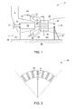
- FIG. 1 is a diagrammatical representation of a gas turbine system having a pylon fuel injection system provided to a reheat combustor in accordance with an exemplary embodiment of the present invention
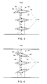
- FIG. 2 is a diagrammatical representation of a pylon fuel injection system in accordance with an exemplary embodiment of the present invention
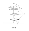
- FIG. 3 is a diagrammatical representation of a portion of a pylon fuel injection system in accordance with an exemplary embodiment of the present invention
- FIG. 4 is a diagrammatical representation of a portion of a pylon fuel injection system in accordance with an exemplary embodiment of the present invention
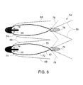
- FIG. 5 is a diagrammatical representation of a portion of a pylon fuel injection system in accordance with an exemplary embodiment of the present invention.
- FIG. 6 is a diagrammatical illustration of the formation of a fuel layer adjacent a profile in a Coanda type fuel injection slot based upon a coanda effect in accordance with an exemplary embodiment of the present invention.
- a combustor system in accordance with the embodiments discussed herein below, includes a pylon fuel injection system coupled to a combustion chamber and configured to inject fuel to the combustion chamber.
- the pylon fuel injection system includes a plurality of radial elements, each radial element having a plurality of first Coanda type fuel injection slots.
- a plurality of transverse elements are provided to each radial element.
- Each transverse element includes a plurality of second Coanda type fuel injection slots.
- a gas turbine system having an exemplary pylon fuel injection system is disclosed.
- the pylon injection systems have a larger number of fuel injection locations creating uniform distribution of fuel in the combustion chamber. Related problems such as combustion dynamics, non-uniform mixing of fuel, and pressure drop within the combustion chamber are mitigated.
- the gas turbine system 10 includes a first combustion chamber 12 (may also be referred to as "first combustor") disposed downstream of a compressor 14.
- a first turbine 16 is disposed downstream of the first combustion chamber 12.
- a second combustion chamber 18 (may also be referred to as "reheat combustor”) is disposed downstream of the first turbine 16.
- a second turbine 20 is disposed downstream of the second combustion chamber 18.
- the compressor 14, the first turbine 16, and the second turbine 20 have a single rotor shaft 22.
- the second turbine 20 may have a separate drive shaft.
- the rotor shaft 22 is supported by two bearings 24, 26 disposed at a front end of the compressor 14 and downstream of the second turbine 20.
- the bearings 24, 26 are mounted respectively on anchor units 28, 30 coupled to a foundation 32.
- the rotor shaft 22 is coupled to a generator 29 via a coupling 31.
- the compressor stage can be subdivided into two partial compressors (not shown) in order, for example, to increase the specific power depending on the operational layout.
- the induced air after compression flows into a casing 34 disposed enclosing an outlet of the compressor 14 and the first turbine 16.
- the first combustion chamber 12 is accommodated in the casing 34.
- the first combustion chamber 12 has a plurality of burners 35 distributed on a periphery at a front end and configured to maintain generation of a hot gas.
- Fuel lances 36 coupled together through a main ring 38 are used to provide fuel supply to the first combustion chamber 12.
- the hot gas (first combustion gas) from the first combustion chamber 12 act on the first turbine 16 immediately downstream, resulting in thermal expansion of the hot gases.
- the partially expanded hot gases from the first turbine 16 flow directly into the second combustion chamber 18.
- the second combustion chamber 18 may have different geometries.
- the second combustion chamber 18 is an aerodynamic path between the first turbine 16 and the second turbine 20 having required length and volume to allow reheat combustion.
- a pylon fuel injection system 40 is disposed radially in the second combustion chamber 18.
- the pylon fuel injection system 40 is configured to inject a fuel into the exhaust gas from the first turbine 16 so as to ensure self-ignition of the exhaust gas in the second combustion chamber 18.
- a hot gas (second combustion gas) generated from the second combustion chamber 18 is subsequently fed to a second turbine 20.
- the hot gas from the second combustion chamber 18 act on the second turbine 20 immediately downstream, resulting in thermal expansion of the hot gases.
- the exemplary system 40 could be applied for any combustors.
- the pylon fuel injection system 40 is disclosed. 'As discussed previously, the pylon fuel injection system 40 is disposed radially within the second combustion chamber or reheat combustor and configured to inject fuel into the second combustion chamber.
- the system 40 includes a plurality of radial elements 42 spaced apart from each other.
- a plurality of transverse elements 44 are provided to each radial element 42.
- the transverse elements 44 are also spaced apart from each other on the corresponding radial element 42.
- Both the radial and transverse elements 42, 44 have a plurality of Coanda type fuel injection slots (not shown in FIG. 2 ) configured to inject fuel into the second combustion chamber.
- the arrangement of the pylon fuel injection system 40 with multiple Coanda type fuel injection locations allows for radial and circumferential distribution of fuel so as to enable a uniform distribution and mixing of fuel within the combustion chamber.
- a portion of the pylon fuel injection system is disclosed.
- a plurality of transverse elements 44 are disposed spaced apart from each other on a corresponding radial element 42. It should be noted herein the transverse elements 44 are aerodynamically shaped.
- the radial element 42 includes a plurality of Coanda type fuel injection slots 46 formed on at least one surface 48.
- Each transverse element 44 includes a plurality of Coanda type fuel injection slots 50 formed on surfaces 52, 54.
- the arrangement of radial elements 42 and the transverse elements 44 facilitates uniform distribution and mixing of fuel in the combustion chamber and also ensures characteristic mixing length associated with the Coanda type injection process to be of the same order as the length scale created by the spacing between the radial elements 42 and the transverse elements 44.
- a "slot" discussed herein may be usually broadly defined as an opening that has one axis longer than another axis.
- the radial and transverse elements 42, 44 may include conical holes, elliptic holes, racetrack shaped holes, round holes, or combinations thereof to provide a Coanda effect.
- the shape or cross-sectional size of the radial elements 42 may change as a function of radius, and that the shape or relative size of the transverse elements 44 may change as a function of location.
- the radial element 42 is aerodynamically shaped.
- the transverse elements 44 include zero lift airfoils.
- the transverse elements 44 have lift capability.
- the lift of the transverse elements 44 may act in concert.
- the lift of the transverse elements 44 may be counter-acting against each other to tailor exit profile of the flow of gas in the combustion chamber.
- the radial elements 42 have lift capability.
- the radial elements 42 may act as de-swirlers to remove swirl from an upstream gas flow from the first turbine.
- the radial elements 42 may act as preswirlers for providing swirl to the downstream flow fed to the second turbine. It should also be noted that provision of the transverse elements 44 facilitates to provide a plurality of distributed locations for fuel injection.
- a portion of the pylon fuel injection system is disclosed. This embodiment is also similar to the embodiment illustrated in FIG. 3 .
- a plurality of transverse elements 44 are disposed spaced apart from each other on each corresponding radial element 42.
- the radial element 42 includes a plurality of Coanda type fuel injection slots 46 formed on at least one surface 48. Additionally, slots 46 may also be formed on side surfaces 56, 58 of each radial element 42.
- a rear surface 60 of the radial element 42 may have holes or openings.
- Each transverse element 44 includes a plurality of Coanda type fuel injection slots 50 formed on surfaces 52, 54. Additionally, slots 50 may also be formed on a trailing edge 62 of each transverse element 44.
- the distributed nature of the plurality of radial elements 42 with the corresponding transverse elements 44 may allow staging of the fuel injection (for example, only injecting fuel at a particular instant from alternate radial elements) for the purpose of load reduction.
- the radial height of the radial elements 42 may also vary. For example, every alternate radial element may be shorter than the other radial elements.
- FIG. 6 is a schematic of an exemplary reaction zone that may be established downstream of the radial element 42.
- the term "Coanda effect" refers to the tendency of a stream of fluid to attach itself to a nearby surface and to remain attached even when the surface curves away from the original direction of fluid motion.
- compressor discharge air flowing over a tandem vane mix with a fuel 66.
- air and fuel mixture boundary layers 68 are formed along external surfaces 70, 72 of the radial element 42 by the Coanda effect created by the Coanda surfaces 74.
- Triple flames 64 may be formed as the concentration of fuel and air varies locally downstream of the trailing edge of the radial element 42. In a fuel rich region, small diffusion flame front pockets 76 are stabilized.
- each diffusion flame may serve to stabilize a first lean partially premixed flame 78 at a minimum flammability limit and a second lean partially premixed flame front 80 formed of diluted products of the other two flames 76 and 78 and excess oxidizer.
- the number of radial elements, transverse elements, spacing between the radial elements, spacing between the transverse elements, number of Coanda type fuel injection slots in the radial elements, number of Coanda type fuel injection slots in the transverse elements, shape of the Coanda type fuel injection slots in the radial and transverse elements, spacing between the Coanda type fuel injection slots, dimensions of the slots, location of the slots in the radial and transverse elements, shape of the radial elements and transverse elements may be varied depending on the application. All such permutations and combinations are envisaged.
- the exemplary pylon fuel injection system facilitates uniform distribution of fuel, uniform mixing of air and fuel, leading to high combustion efficiency with lower emissions, acoustics, and pressure loss.
Landscapes
- Engineering & Computer Science (AREA)
- Chemical & Material Sciences (AREA)
- Combustion & Propulsion (AREA)
- Mechanical Engineering (AREA)
- General Engineering & Computer Science (AREA)
- Fuel-Injection Apparatus (AREA)
Applications Claiming Priority (1)
| Application Number | Priority Date | Filing Date | Title |
|---|---|---|---|
| US12/535,313 US8763400B2 (en) | 2009-08-04 | 2009-08-04 | Aerodynamic pylon fuel injector system for combustors |
Publications (2)
| Publication Number | Publication Date |
|---|---|
| EP2295860A2 true EP2295860A2 (de) | 2011-03-16 |
| EP2295860A3 EP2295860A3 (de) | 2014-10-01 |
Family
ID=42830295
Family Applications (1)
| Application Number | Title | Priority Date | Filing Date |
|---|---|---|---|
| EP10171758.5A Withdrawn EP2295860A3 (de) | 2009-08-04 | 2010-08-03 | Aerodynamisches Pylonbrennstoffeinspritzsystem für Brennkammern |
Country Status (4)
| Country | Link |
|---|---|
| US (1) | US8763400B2 (de) |
| EP (1) | EP2295860A3 (de) |
| JP (1) | JP2011033332A (de) |
| CN (1) | CN101995019A (de) |
Families Citing this family (24)
| Publication number | Priority date | Publication date | Assignee | Title |
|---|---|---|---|---|
| US8899494B2 (en) | 2011-03-31 | 2014-12-02 | General Electric Company | Bi-directional fuel injection method |
| US8522553B2 (en) * | 2011-09-14 | 2013-09-03 | General Electric Company | System and method for conditioning a working fluid in a combustor |
| US9032721B2 (en) * | 2011-12-14 | 2015-05-19 | Siemens Energy, Inc. | Gas turbine engine exhaust diffuser including circumferential vane |
| EP2644997A1 (de) | 2012-03-26 | 2013-10-02 | Alstom Technology Ltd | Mischanordnung zum Mischen von Kraftstoff mit einem Strom aus sauerstoffhaltigem Gas |
| US20130298563A1 (en) * | 2012-05-14 | 2013-11-14 | General Electric Company | Secondary Combustion System |
| CA2830031C (en) * | 2012-10-23 | 2016-03-15 | Alstom Technology Ltd. | Burner for a can combustor |
| EP2728258A1 (de) * | 2012-11-02 | 2014-05-07 | Alstom Technology Ltd | Gasturbine |
| US20160040881A1 (en) * | 2013-03-14 | 2016-02-11 | United Technologies Corporation | Gas turbine engine combustor |
| JP6266775B2 (ja) | 2013-07-26 | 2018-01-24 | エムアールエイ・システムズ・エルエルシー | 航空機エンジンパイロン |
| EP2894405B1 (de) * | 2014-01-10 | 2016-11-23 | General Electric Technology GmbH | Sequentielle Verbrennungsanordnung mit Verdünnungsgas |
| US10221720B2 (en) | 2014-09-03 | 2019-03-05 | Honeywell International Inc. | Structural frame integrated with variable-vectoring flow control for use in turbine systems |
| EP3115693B1 (de) * | 2015-07-10 | 2021-09-01 | Ansaldo Energia Switzerland AG | Sequentielle brennkammer und verfahren zum betrieb davon |
| US10393020B2 (en) * | 2015-08-26 | 2019-08-27 | Rohr, Inc. | Injector nozzle configuration for swirl anti-icing system |
| WO2017074345A1 (en) * | 2015-10-28 | 2017-05-04 | Siemens Energy, Inc. | Combustion system with injector assembly including aerodynamically-shaped body and/or ejection orifices |
| WO2017074343A1 (en) * | 2015-10-28 | 2017-05-04 | Siemens Energy, Inc. | Combustion system with injector assembly including aerodynamically-shaped body |
| CN106765311B (zh) * | 2016-12-13 | 2019-04-09 | 北京航空航天大学 | 一种带直角三角形凹槽的超燃冲压燃烧室支板 |
| US10718523B2 (en) | 2017-05-12 | 2020-07-21 | General Electric Company | Fuel injectors with multiple outlet slots for use in gas turbine combustor |
| US11149948B2 (en) | 2017-08-21 | 2021-10-19 | General Electric Company | Fuel nozzle with angled main injection ports and radial main injection ports |
| US12065970B2 (en) * | 2021-10-22 | 2024-08-20 | Hamilton Sundstrand Corporation | Coke catching screen |
| JP7650843B2 (ja) * | 2022-03-30 | 2025-03-25 | 三菱重工業株式会社 | 燃焼器及びガスタービン |
| US11971170B1 (en) | 2022-12-30 | 2024-04-30 | Ge Infrastructure Technology Llc | System and method having flame stabilizers for isothermal expansion in turbine stage of gas turbine engine |
| US12037951B1 (en) * | 2022-12-30 | 2024-07-16 | Ge Infrastructure Technology Llc | System and method having load control for isothermal expansion in turbine stage of gas turbine engine |
| US12540581B2 (en) | 2022-12-30 | 2026-02-03 | Ge Vernova Infrastructure Technology Llc | System and method having fluid injectors for isothermal expansion in turbine stage of gas turbine engine |
| US11891949B1 (en) | 2022-12-30 | 2024-02-06 | Ge Infrastructure Technology Llc | System and method having multi-fluid injectors for isothermal expansion in turbine stage of gas turbine engine |
Family Cites Families (48)
| Publication number | Priority date | Publication date | Assignee | Title |
|---|---|---|---|---|
| US3008669A (en) * | 1955-01-05 | 1961-11-14 | Frank I Tanczos | Ramjet missile |
| US2995317A (en) * | 1955-09-14 | 1961-08-08 | Metallbau Semler G M B H | External combustion stato-jet engine |
| US2970438A (en) * | 1958-03-04 | 1961-02-07 | Curtiss Wright Corp | Circular fuel spray bars |
| US3386249A (en) * | 1964-01-10 | 1968-06-04 | Navy Usa | Fuel injection pylons |
| US4214722A (en) * | 1974-12-13 | 1980-07-29 | Tamura Raymond M | Pollution reducing aircraft propulsion |
| US4147029A (en) * | 1976-01-02 | 1979-04-03 | General Electric Company | Long duct mixed flow gas turbine engine |
| US4197700A (en) * | 1976-10-13 | 1980-04-15 | Jahnig Charles E | Gas turbine power system with fuel injection and combustion catalyst |
| FR2392231A1 (fr) * | 1977-05-23 | 1978-12-22 | Inst Francais Du Petrole | Turbine a gaz comportant une chambre de combustion entre les etages de la turbine |
| US4423595A (en) | 1982-05-27 | 1984-01-03 | United Technologies Corporation | Augmentor residual fuel drain apparatus |
| FR2696502B1 (fr) * | 1992-10-07 | 1994-11-04 | Snecma | Dispositif de post-combustion pour turbo réacteur double flux. |
| US5036657A (en) * | 1987-06-25 | 1991-08-06 | General Electric Company | Dual manifold fuel system |
| US4903478A (en) | 1987-06-25 | 1990-02-27 | General Electric Company | Dual manifold fuel system |
| US4893468A (en) * | 1987-11-30 | 1990-01-16 | General Electric Company | Emissions control for gas turbine engine |
| US4887425A (en) | 1988-03-18 | 1989-12-19 | General Electric Company | Fuel spraybar |
| US4976102A (en) * | 1988-05-09 | 1990-12-11 | General Electric Company | Unducted, counterrotating gearless front fan engine |
| FR2637018A1 (fr) | 1988-09-28 | 1990-03-30 | Snecma | Dispositif d'injection de gaz pour propulseur combine turbo-stato-fusee |
| US5052176A (en) * | 1988-09-28 | 1991-10-01 | Societe Nationale D'etude Et De Construction De Moteurs D'aviation | Combination turbojet-ramjet-rocket propulsion system |
| US5099644A (en) | 1990-04-04 | 1992-03-31 | General Electric Company | Lean staged combustion assembly |
| US5203796A (en) * | 1990-08-28 | 1993-04-20 | General Electric Company | Two stage v-gutter fuel injection mixer |
| US5207064A (en) * | 1990-11-21 | 1993-05-04 | General Electric Company | Staged, mixed combustor assembly having low emissions |
| JP2580510B2 (ja) | 1991-08-19 | 1997-02-12 | 科学技術庁航空宇宙技術研究所長 | 高速航空エンジン用燃焼器 |
| CH687269A5 (de) | 1993-04-08 | 1996-10-31 | Abb Management Ag | Gasturbogruppe. |
| CH687347A5 (de) * | 1993-04-08 | 1996-11-15 | Abb Management Ag | Wärmeerzeuger. |
| FR2706588B1 (fr) * | 1993-06-16 | 1995-07-21 | Snecma | Système d'injection de carburant pour chambre de combustion. |
| US5385015A (en) * | 1993-07-02 | 1995-01-31 | United Technologies Corporation | Augmentor burner |
| JP3511075B2 (ja) | 1994-03-11 | 2004-03-29 | 川崎重工業株式会社 | 低公害燃焼器およびその燃焼制御方法 |
| US5826429A (en) * | 1995-12-22 | 1998-10-27 | General Electric Co. | Catalytic combustor with lean direct injection of gas fuel for low emissions combustion and methods of operation |
| FR2750169B1 (fr) | 1996-06-24 | 1998-08-21 | Aerospatiale | Dispositif d'injection de combustible pour statoreacteur fonctionnant a un nombre de mach eleve |
| US5927067A (en) * | 1997-11-13 | 1999-07-27 | United Technologies Corporation | Self-cleaning augmentor fuel manifold |
| EP0921292B1 (de) * | 1997-12-08 | 2003-09-10 | ALSTOM (Switzerland) Ltd | Verfahren zur Regelung einer Gasturbogruppe |
| US6125627A (en) * | 1998-08-11 | 2000-10-03 | Allison Advanced Development Company | Method and apparatus for spraying fuel within a gas turbine engine |
| US6295801B1 (en) * | 1998-12-18 | 2001-10-02 | General Electric Company | Fuel injector bar for gas turbine engine combustor having trapped vortex cavity |
| US6200092B1 (en) * | 1999-09-24 | 2001-03-13 | General Electric Company | Ceramic turbine nozzle |
| US6260349B1 (en) * | 2000-03-17 | 2001-07-17 | Kenneth F. Griffiths | Multi-stage turbo-machines with specific blade dimension ratios |
| US6564555B2 (en) * | 2001-05-24 | 2003-05-20 | Allison Advanced Development Company | Apparatus for forming a combustion mixture in a gas turbine engine |
| US6619026B2 (en) * | 2001-08-27 | 2003-09-16 | Siemens Westinghouse Power Corporation | Reheat combustor for gas combustion turbine |
| US6868676B1 (en) * | 2002-12-20 | 2005-03-22 | General Electric Company | Turbine containing system and an injector therefor |
| US7416137B2 (en) * | 2003-01-22 | 2008-08-26 | Vast Power Systems, Inc. | Thermodynamic cycles using thermal diluent |
| US6983601B2 (en) * | 2004-05-28 | 2006-01-10 | General Electric Company | Method and apparatus for gas turbine engines |
| US20070033945A1 (en) * | 2005-08-10 | 2007-02-15 | Goldmeer Jeffrey S | Gas turbine system and method of operation |
| US8266911B2 (en) * | 2005-11-14 | 2012-09-18 | General Electric Company | Premixing device for low emission combustion process |
| US7467518B1 (en) | 2006-01-12 | 2008-12-23 | General Electric Company | Externally fueled trapped vortex cavity augmentor |
| US7861977B1 (en) * | 2006-03-13 | 2011-01-04 | The United States Of America As Represented By The Secretary Of The Navy | Adaptive material actuators for Coanda effect circulation control slots |
| GB0617925D0 (en) * | 2006-09-12 | 2006-10-18 | Rolls Royce Plc | Components for a gas turbine engine |
| US20080078182A1 (en) * | 2006-09-29 | 2008-04-03 | Andrei Tristan Evulet | Premixing device, gas turbines comprising the premixing device, and methods of use |
| US20080104961A1 (en) * | 2006-11-08 | 2008-05-08 | Ronald Scott Bunker | Method and apparatus for enhanced mixing in premixing devices |
| US7832212B2 (en) * | 2006-11-10 | 2010-11-16 | General Electric Company | High expansion fuel injection slot jet and method for enhancing mixing in premixing devices |
| US20080134685A1 (en) | 2006-12-07 | 2008-06-12 | Ronald Scott Bunker | Gas turbine guide vanes with tandem airfoils and fuel injection and method of use |
-
2009
- 2009-08-04 US US12/535,313 patent/US8763400B2/en not_active Expired - Fee Related
-
2010
- 2010-07-28 JP JP2010168722A patent/JP2011033332A/ja not_active Ceased
- 2010-08-03 EP EP10171758.5A patent/EP2295860A3/de not_active Withdrawn
- 2010-08-04 CN CN2010102545832A patent/CN101995019A/zh active Pending
Also Published As
| Publication number | Publication date |
|---|---|
| JP2011033332A (ja) | 2011-02-17 |
| US8763400B2 (en) | 2014-07-01 |
| EP2295860A3 (de) | 2014-10-01 |
| US20110030375A1 (en) | 2011-02-10 |
| CN101995019A (zh) | 2011-03-30 |
Similar Documents
| Publication | Publication Date | Title |
|---|---|---|
| US8763400B2 (en) | Aerodynamic pylon fuel injector system for combustors | |
| EP2889542B1 (de) | Verfahren zum betrieb einer brennkammer für eine gasturbine und brennkammer für eine gasturbine | |
| EP3303929B1 (de) | Brennkammer | |
| US8381532B2 (en) | Bled diffuser fed secondary combustion system for gas turbines | |
| US10072846B2 (en) | Trapped vortex cavity staging in a combustor | |
| EP2738355B1 (de) | Gasturbinentriebwerk und zugehöriges Verfahren | |
| US20110219776A1 (en) | Aerodynamic flame stabilizer | |
| CN101377305A (zh) | 带径向分级流通道的预混合器和混合空气及燃气的方法 | |
| CN108019777A (zh) | 多点中心体喷射器小型混合燃料喷嘴组件 | |
| KR101774630B1 (ko) | 가스 터빈 엔진에 사용되는 예비혼합된 연료와 공기를 가진 접선방향의 애뉼러형 연소실 | |
| CN102840600B (zh) | 涡轮组件以及用于与其一起使用的过渡喷嘴 | |
| JP2017116250A (ja) | ガスタービンにおける燃料噴射器および段階的燃料噴射システム | |
| CN102042089A (zh) | 低btu燃料喷射系统 | |
| EP3220050A1 (de) | Brenner für eine gasturbine | |
| US11041623B2 (en) | Gas turbine combustor with heat exchanger between rich combustion zone and secondary combustion zone | |
| JP4961415B2 (ja) | ガスタービン燃焼器 | |
| JP2014526030A (ja) | ガス・タービン・エンジンで使用するための予め混合された接線方向の燃料空気のノズルを備えた環状筒型燃焼器 | |
| EP3169938B1 (de) | Axial gestufte gasturbinenbrennkammer mit zwischenstufigem vormischer | |
| JP4477039B2 (ja) | ガスタービンエンジンの燃焼装置 | |
| JP5934795B2 (ja) | ガス・タービン・エンジンで使用するための接線方向で火炎のない環状燃焼器 | |
| CN112840160A (zh) | 燃烧器以及具备该燃烧器的燃气轮机 |
Legal Events
| Date | Code | Title | Description |
|---|---|---|---|
| PUAI | Public reference made under article 153(3) epc to a published international application that has entered the european phase |
Free format text: ORIGINAL CODE: 0009012 |
|
| AK | Designated contracting states |
Kind code of ref document: A2 Designated state(s): AL AT BE BG CH CY CZ DE DK EE ES FI FR GB GR HR HU IE IS IT LI LT LU LV MC MK MT NL NO PL PT RO SE SI SK SM TR |
|
| AX | Request for extension of the european patent |
Extension state: BA ME RS |
|
| PUAL | Search report despatched |
Free format text: ORIGINAL CODE: 0009013 |
|
| AK | Designated contracting states |
Kind code of ref document: A3 Designated state(s): AL AT BE BG CH CY CZ DE DK EE ES FI FR GB GR HR HU IE IS IT LI LT LU LV MC MK MT NL NO PL PT RO SE SI SK SM TR |
|
| AX | Request for extension of the european patent |
Extension state: BA ME RS |
|
| RIC1 | Information provided on ipc code assigned before grant |
Ipc: F23R 3/20 20060101ALI20140825BHEP Ipc: F23D 14/64 20060101AFI20140825BHEP Ipc: F23R 3/28 20060101ALI20140825BHEP |
|
| STAA | Information on the status of an ep patent application or granted ep patent |
Free format text: STATUS: THE APPLICATION IS DEEMED TO BE WITHDRAWN |
|
| 18D | Application deemed to be withdrawn |
Effective date: 20150303 |