EP2295865A2 - Befestigung eines Hitzeschildes in einer Brennkammer - Google Patents
Befestigung eines Hitzeschildes in einer Brennkammer Download PDFInfo
- Publication number
- EP2295865A2 EP2295865A2 EP10169338A EP10169338A EP2295865A2 EP 2295865 A2 EP2295865 A2 EP 2295865A2 EP 10169338 A EP10169338 A EP 10169338A EP 10169338 A EP10169338 A EP 10169338A EP 2295865 A2 EP2295865 A2 EP 2295865A2
- Authority
- EP
- European Patent Office
- Prior art keywords
- tile
- combustor
- wall
- boss
- recess
- Prior art date
- Legal status (The legal status is an assumption and is not a legal conclusion. Google has not performed a legal analysis and makes no representation as to the accuracy of the status listed.)
- Withdrawn
Links
- 238000001816 cooling Methods 0.000 claims description 31
- 125000006850 spacer group Chemical group 0.000 claims description 20
- 238000002485 combustion reaction Methods 0.000 claims description 8
- 238000003754 machining Methods 0.000 description 5
- 239000007789 gas Substances 0.000 description 4
- 238000005266 casting Methods 0.000 description 2
- 239000000919 ceramic Substances 0.000 description 2
- 230000013011 mating Effects 0.000 description 2
- 230000001681 protective effect Effects 0.000 description 2
- 239000013598 vector Substances 0.000 description 2
- 238000010586 diagram Methods 0.000 description 1
- 238000005553 drilling Methods 0.000 description 1
- 239000000463 material Substances 0.000 description 1
- 238000002844 melting Methods 0.000 description 1
- 230000008018 melting Effects 0.000 description 1
- 238000000034 method Methods 0.000 description 1
- 238000012986 modification Methods 0.000 description 1
- 230000004048 modification Effects 0.000 description 1
- NJPPVKZQTLUDBO-UHFFFAOYSA-N novaluron Chemical compound C1=C(Cl)C(OC(F)(F)C(OC(F)(F)F)F)=CC=C1NC(=O)NC(=O)C1=C(F)C=CC=C1F NJPPVKZQTLUDBO-UHFFFAOYSA-N 0.000 description 1
Images


Classifications
-
- F—MECHANICAL ENGINEERING; LIGHTING; HEATING; WEAPONS; BLASTING
- F23—COMBUSTION APPARATUS; COMBUSTION PROCESSES
- F23R—GENERATING COMBUSTION PRODUCTS OF HIGH PRESSURE OR HIGH VELOCITY, e.g. GAS-TURBINE COMBUSTION CHAMBERS
- F23R3/00—Continuous combustion chambers using liquid or gaseous fuel
- F23R3/007—Continuous combustion chambers using liquid or gaseous fuel constructed mainly of ceramic components
-
- F—MECHANICAL ENGINEERING; LIGHTING; HEATING; WEAPONS; BLASTING
- F23—COMBUSTION APPARATUS; COMBUSTION PROCESSES
- F23R—GENERATING COMBUSTION PRODUCTS OF HIGH PRESSURE OR HIGH VELOCITY, e.g. GAS-TURBINE COMBUSTION CHAMBERS
- F23R3/00—Continuous combustion chambers using liquid or gaseous fuel
- F23R3/002—Wall structures
-
- F—MECHANICAL ENGINEERING; LIGHTING; HEATING; WEAPONS; BLASTING
- F23—COMBUSTION APPARATUS; COMBUSTION PROCESSES
- F23R—GENERATING COMBUSTION PRODUCTS OF HIGH PRESSURE OR HIGH VELOCITY, e.g. GAS-TURBINE COMBUSTION CHAMBERS
- F23R2900/00—Special features of, or arrangements for continuous combustion chambers; Combustion processes therefor
- F23R2900/03041—Effusion cooled combustion chamber walls or domes
-
- F—MECHANICAL ENGINEERING; LIGHTING; HEATING; WEAPONS; BLASTING
- F23—COMBUSTION APPARATUS; COMBUSTION PROCESSES
- F23R—GENERATING COMBUSTION PRODUCTS OF HIGH PRESSURE OR HIGH VELOCITY, e.g. GAS-TURBINE COMBUSTION CHAMBERS
- F23R2900/00—Special features of, or arrangements for continuous combustion chambers; Combustion processes therefor
- F23R2900/03042—Film cooled combustion chamber walls or domes
-
- F—MECHANICAL ENGINEERING; LIGHTING; HEATING; WEAPONS; BLASTING
- F23—COMBUSTION APPARATUS; COMBUSTION PROCESSES
- F23R—GENERATING COMBUSTION PRODUCTS OF HIGH PRESSURE OR HIGH VELOCITY, e.g. GAS-TURBINE COMBUSTION CHAMBERS
- F23R3/00—Continuous combustion chambers using liquid or gaseous fuel
- F23R3/42—Continuous combustion chambers using liquid or gaseous fuel characterised by the arrangement or form of the flame tubes or combustion chambers
- F23R3/60—Support structures; Attaching or mounting means
-
- Y—GENERAL TAGGING OF NEW TECHNOLOGICAL DEVELOPMENTS; GENERAL TAGGING OF CROSS-SECTIONAL TECHNOLOGIES SPANNING OVER SEVERAL SECTIONS OF THE IPC; TECHNICAL SUBJECTS COVERED BY FORMER USPC CROSS-REFERENCE ART COLLECTIONS [XRACs] AND DIGESTS
- Y10—TECHNICAL SUBJECTS COVERED BY FORMER USPC
- Y10T—TECHNICAL SUBJECTS COVERED BY FORMER US CLASSIFICATION
- Y10T428/00—Stock material or miscellaneous articles
- Y10T428/24—Structurally defined web or sheet [e.g., overall dimension, etc.]
- Y10T428/24479—Structurally defined web or sheet [e.g., overall dimension, etc.] including variation in thickness
Definitions
- the present invention relates to a tile for lining the hot side of a wall of a combustor.
- the temperature of the gases released by the combustion process in a gas turbine engine may peak above 2100°C and average 1500°C. This is much higher than the melting point of combustion chamber materials.
- many gas turbine engine combustors employ ceramic or ceramic-coated tiles to line the combustor wall.
- the individual tiles are attached to the combustor wall (e.g. the annular "cold skin” which forms the sides of the combustor) and cooling air passes through holes in the wall to impinge on the cold side of the tiles. The air then moves through a series of pedestals projecting from the cold side of the tiles to improve the convective heat transfer coefficient.
- the combustor wall e.g. the annular "cold skin” which forms the sides of the combustor
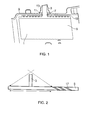
- Figure 1 shows a cut-away section through a combustor and illustrates a conventional fastening arrangement for a lining tile.
- the tile 1 has a threaded fixing stud 3 which extends from the cold side of the tile body 5 and passes through a hole 7 in the combustor wall 9.
- a washer 11 is placed over the stud and a nut 13 screws onto the stud to pull the tile towards the combustor wall, pedestals 15 on the cold side of the tile body determining the final spacing between the tile body and the wall.
- the higher combustor temperatures which this requires can require different cooling arrangements.
- pedestal cooling may be superseded by impingement effusion tile cooling arrangements.
- the tile body has an array of effusion cooling through-holes, at a low angle (e.g. about 20°) to the surface. Cooling air effusing from the holes forms a protective cooling layer on the hot side of the tiles.
- the cooling air effusion holes may be formed by laser machining of the tile body.
- this presents a problem in that laser machining is a line of sight process.
- the fixing stud 3 obstructs laser drilling of effusion holes 17 in an area of the tile body 5 around the stud because of interference of the stud with the laser tool and/or the path (dashed, single headed arrow lines) of the laser beam.
- the result can be a significant area (the extent of which is indicated by the double headed arrow line) around each stud that is devoid of cooling holes.
- approach vectors may have to be defined for the laser that avoid interference with the studs to produce holes in the vicinity of the studs. This requires extra programming and extra machining time, and may produce sub-optimal X, Y positions of the holes on the surface of the tile and/or sub-optimal angles of the holes to the surface.
- a first aspect of the present invention provides a tile for lining a wall of a combustor the wall having a hot surface intended to face a combustion volume and a corresponding cold surface intended to face away from the combustion volume, the tile having a tile body with one or more bosses protruding from a cold side thereof, the or each boss extending, in use, through the wall of the combustor and having a threaded recess formed therein for threadingly connecting with a bolt which is inserted into the recess from the cold side of the combustor wall, whereby the bolt fastens the tile to the combustor wall.
- Such a boss can have a significantly reduced height relative to a conventional fixing stud, and thus, in a tile with laser machined effusion holes, the area around the boss which can be problematic to machine may be much reduced.
- the boss is therefore particularly advantageous when used in relation to a tile with laser machined effusion holes, it may also be used on tiles with other types of cooling features, such as cooling pedestals.
- the tile may have any one or any combination of the following optional features.
- the tile body has a generally rectangular or square shape, although it may be curved to e.g. fit to an annular combustor wall. There may be a boss at each corner of such a tile.
- the combustor is a combustor of a gas turbine engine.
- a plurality of cooling air effusion holes e.g. angled at 20° or less to the hot side surface of the tile body, traverse the tile body.
- the tile body has one or more spacing projections (such as one or more rails extending along the perimeter of the tile body) protruding from the cold side thereof, the spacing projections engaging with the hot side of the combustor wall when the tile is fastened thereto to determine a spacing of the tile body from the combustor wall.
- spacing projections being discrete from the or each boss, avoid the need for the boss to set the spacing of the tile body from the combustor wall. Cooling air can flow into the gap between the tile body and the combustor wall and thence to e.g. the effusion holes.
- the boss can be made as long as is necessary to accommodate in the recess a desired number of thread turns. However, as an alternative to increasing the height of the boss to accommodate more thread turns, optionally the recess may be extended into the tile body.
- the or each boss may have a respective spacer which, in use, interposes between a head of the bolt and the boss, the spacer engaging at one side with the head of the bolt and at the opposite side with the cold side of the combustor wall.
- the spacer can thus determine a spacing between the head of the bolt and the cold side of the combustor wall.
- the spacer may contain one or more cooling air passages through which cooling air is sent to the hot side of the combustor wall e.g. to a gap between the tile body and the combustor wall.
- one or more channels may extend through the or each boss to carry cooling air to the foot of the recess.
- the or each channel fluidly connects to one or more effusion holes extending from the foot of the recess to the hot side of the tile body. In this way, cooling air may introduced to the region of the tile body which in a tile with a conventional fixing stud is difficult to provide with effusion holes.
- cooling air carried by the one or more channels through the boss is received from cooling air passage(s) of the spacer.
- a second aspect of the present invention provides a combustor having one or more walls lined with tiles according to the previous aspect (the tile optionally having any one or any combination of the referred to above).
- the lined wall(s) can be an annular side wall of the combustor, and/or a heat shield front wall of the combustor.
- hot side and cold side and hot surface and cold surface relate both to their intended and actual use. Accordingly, where the combustor or tile is not in use it is entirely feasible for the hot and cold sides or surfaces to be at the same ambient temperature. However, when the combustor or tile is in use the hot surface will be the surface facing towards the combustion volume and the cold surface will be an opposing surface facing away from the combustion volume.
- FIG 3 shows a schematic perspective view of a tile 101 according to a first embodiment of the present invention and the corresponding portion of a combustor wall 109 (i.e. cold skin) to which the tile is fixed.
- a combustor wall i.e. cold skin
- the tile and portion of combustor wall are as flat objects, although in reality they would curve around the annulus of the wall.
- the tile has a rectangular tile body 105
- Figure 4 shows a schematic cross-section through one of the fixing arrangements which are provided at the corner regions of the body.
- An array of cooling air effusion holes 117 traverses the tile body, but in Figures 3 and 4 only a small number of these holes are shown.
- Each fixing arrangement comprises a boss 119 protruding from the cold side of the tile body 105 to extend through a hole 129 in the combustor wall 109.
- the boss has a threaded recess 121 into which is screwed a bolt 123 from the cold side of the combustor wall.
- a ringshaped spacer 125 encircles the boss where it projects from the cold side of the combustor wall.
- the bolt passes through the central hole 125a in the spacer with the head 123a of the bolt pushing down on the top of the spacer to urge it against the combustor wall and thereby determine the spacing between the head 123a of the bolt and the wall.
- the head of the bolt and the spacer which may have a curved surface to match the curved combustor wall, seal respectively the central hole in the spacer and the hole in the combustor wall.
- a rail 127 extends around the perimeter of the cold side of the tile body and is pulled by the bolt against the hot side of the combustor wall to determine the spacing between the tile body from the combustor wall. Together, the spacer and the rail determine the extent to which the bolt penetrates into the recess.
- Figure 3 the bolt and fixing spacer of only one of the fixing arrangements are shown.
- the distance marked with the doubled headed arrowed line in Figure 4 can be used to threadingly connect the bolt 123 to the boss 119, the distance by which the boss projects from the cold side of the combustor wall 109 is significantly reduced relative to the equivalent projection distance of the fixing stud 3 of the conventional tile 5, shown in Figures 1 and 2 , in which all mating threads are situated outside the combustor wall 9.
- This facilitates laser machining of the effusion holes 117 of the tile 105 of the first embodiment at a close proximity to the boss, reducing the area around the boss which is devoid of effusion holes or for which different laser tool approach vectors have to be programmed, and ultimately improving the cooling performance of the tile.
- the projection distance of the boss can be further reduced if the recess 121 extends into the tile body 105, allowing the mating threads to be lowered in the recess.
- the spacer 125 has a plurality of radially extending passages 131 which carry cooling air from the cold side of the combustor wall 109 to a central cavity 133 formed in the spacer. From here, the cooling air passes through the hole 129 in the combustor wall 109, into the gap maintained between the combustor wall and the tile body 105, and then out through the effusion holes 117 to provide a protective cooling layer on the hot side of the tile body.
- FIG. 5 shows a schematic cross-section through a fixing arrangement of a tile according to a second embodiment of the present invention.
- Features of the tile of the second embodiment which are the same as features of the tile of the first embodiment shown in Figures 3 and 4 share the same reference numbers.
- the tile 105 of the second embodiment has enhancements to improve the cooling of the tile in the vicinity of the boss 119. More specifically, one or more channels 135 run along the side of the recess 121. Cooling air conveyed by the radially extending passages 131 in the spacer 125 is thus carried, via the central cavity 133 of the spacer, to the channel or channels 135 and thence to the foot of the recess. From here, an effusion hole 137 extends across the tile body bringing cooling air to a position directly underneath the boss 119.
- the tile may have one or more channels 139 extending between the recess and the radially outer surface of the boss, e.g. to exit in the hole 129 of the combustor wall 109 (as shown in Figure 5 ) or in the central cavity of the spacer.
- the channel or channels 135 running along the side of the recess 121 could be formed during casting of the tile 101.
- the channel or channels 139 extending between the recess 121 and the radially outer surface of the boss 119 could be formed by post-casting machining.
- the tiles 101 of the first and second embodiments have been described in respect of an annular combustor cold skin, the invention could also be applied to tiles lining the heat shield (front wall) of a combustor.
Landscapes
- Engineering & Computer Science (AREA)
- Chemical & Material Sciences (AREA)
- Combustion & Propulsion (AREA)
- Mechanical Engineering (AREA)
- General Engineering & Computer Science (AREA)
- Ceramic Engineering (AREA)
- Furnace Housings, Linings, Walls, And Ceilings (AREA)
- Finishing Walls (AREA)
Applications Claiming Priority (1)
| Application Number | Priority Date | Filing Date | Title |
|---|---|---|---|
| GB0913580A GB0913580D0 (en) | 2009-08-05 | 2009-08-05 | Combustor tile |
Publications (2)
| Publication Number | Publication Date |
|---|---|
| EP2295865A2 true EP2295865A2 (de) | 2011-03-16 |
| EP2295865A3 EP2295865A3 (de) | 2014-09-17 |
Family
ID=41129607
Family Applications (1)
| Application Number | Title | Priority Date | Filing Date |
|---|---|---|---|
| EP10169338.0A Withdrawn EP2295865A3 (de) | 2009-08-05 | 2010-07-13 | Befestigung eines Hitzeschildes in einer Brennkammer |
Country Status (3)
| Country | Link |
|---|---|
| US (1) | US8833084B2 (de) |
| EP (1) | EP2295865A3 (de) |
| GB (1) | GB0913580D0 (de) |
Cited By (5)
| Publication number | Priority date | Publication date | Assignee | Title |
|---|---|---|---|---|
| EP2700877A2 (de) | 2012-08-21 | 2014-02-26 | Rolls-Royce Deutschland Ltd & Co KG | Gasturbinenbrennkammer mit prallgekühlten Bolzen der Brennkammerschindeln |
| EP2743585A1 (de) * | 2012-12-12 | 2014-06-18 | Rolls-Royce plc | Brennkammer |
| DE102013226488A1 (de) * | 2013-12-18 | 2015-06-18 | Rolls-Royce Deutschland Ltd & Co Kg | Unterlegscheibe einer Brennkammerschindel einer Gasturbine |
| DE102015225107A1 (de) | 2015-12-14 | 2017-06-14 | Rolls-Royce Deutschland Ltd & Co Kg | Gasturbinenbrennkammer mit Schindelbefestigung mittels Rastelementen |
| DE102016217876A1 (de) | 2016-09-19 | 2018-03-22 | Rolls-Royce Deutschland Ltd & Co Kg | Brennkammerwand einer Gasturbine mit Befestigung einer Brennkammerschindel |
Families Citing this family (31)
| Publication number | Priority date | Publication date | Assignee | Title |
|---|---|---|---|---|
| US9328923B2 (en) * | 2012-10-10 | 2016-05-03 | General Electric Company | System and method for separating fluids |
| DE102012022259A1 (de) * | 2012-11-13 | 2014-05-28 | Rolls-Royce Deutschland Ltd & Co Kg | Brennkammerschindel einer Gasturbine sowie Verfahren zu deren Herstellung |
| DE102012022199A1 (de) * | 2012-11-13 | 2014-05-28 | Rolls-Royce Deutschland Ltd & Co Kg | Brennkammerschindel einer Gasturbine |
| DE102012023297A1 (de) | 2012-11-28 | 2014-06-12 | Rolls-Royce Deutschland Ltd & Co Kg | Schindelbefestigungsanordnung einer Gasturbinenbrennkammer |
| GB201303057D0 (en) * | 2013-02-21 | 2013-04-03 | Rolls Royce Plc | A combustion chamber |
| CA2904200A1 (en) * | 2013-03-05 | 2014-09-12 | Rolls-Royce Corporation | Dual-wall impingement, convection, effusion combustor tile |
| WO2014149108A1 (en) | 2013-03-15 | 2014-09-25 | Graves Charles B | Shell and tiled liner arrangement for a combustor |
| WO2015009384A1 (en) * | 2013-07-16 | 2015-01-22 | United Technologies Corporation | Gas turbine engine with ceramic panel |
| GB201317006D0 (en) * | 2013-09-25 | 2013-11-06 | Rolls Royce Plc | Component for attaching to a wall |
| EP3066388B1 (de) * | 2013-11-04 | 2024-04-10 | RTX Corporation | Gasturbinenbrennkammer-hitzeschild mit mehrwinkligen kühlungsöffnungen |
| EP3066391B1 (de) * | 2013-11-05 | 2019-01-16 | United Technologies Corporation | Gekühlte brennkammerschwebewandplatte |
| DE102013223258A1 (de) * | 2013-11-14 | 2015-06-03 | Rolls-Royce Deutschland Ltd & Co Kg | Brennkammerhitzeabschirmelement einer Gasturbine |
| GB201322838D0 (en) | 2013-12-23 | 2014-02-12 | Rolls Royce Plc | A combustion chamber |
| DE102014204472A1 (de) * | 2014-03-11 | 2015-09-17 | Rolls-Royce Deutschland Ltd & Co Kg | Brennkammerschindel einer Gasturbine |
| GB201413194D0 (en) * | 2014-07-25 | 2014-09-10 | Rolls Royce Plc | A liner element for a combustor, and a related method |
| GB201418042D0 (en) * | 2014-10-13 | 2014-11-26 | Rolls Royce Plc | A liner element for a combustor, and a related method |
| DE102014221225A1 (de) * | 2014-10-20 | 2016-04-21 | Siemens Aktiengesellschaft | Hitzeschildelement und Verfahren zu seiner Herstellung |
| US10094564B2 (en) * | 2015-04-17 | 2018-10-09 | Pratt & Whitney Canada Corp. | Combustor dilution hole cooling system |
| US10935240B2 (en) | 2015-04-23 | 2021-03-02 | Raytheon Technologies Corporation | Additive manufactured combustor heat shield |
| US10648669B2 (en) * | 2015-08-21 | 2020-05-12 | Rolls-Royce Corporation | Case and liner arrangement for a combustor |
| US10386072B2 (en) | 2015-09-02 | 2019-08-20 | Pratt & Whitney Canada Corp. | Internally cooled dilution hole bosses for gas turbine engine combustors |
| US10935236B2 (en) | 2016-11-10 | 2021-03-02 | Raytheon Technologies Corporation | Non-planar combustor liner panel for a gas turbine engine combustor |
| US10935235B2 (en) | 2016-11-10 | 2021-03-02 | Raytheon Technologies Corporation | Non-planar combustor liner panel for a gas turbine engine combustor |
| US10830433B2 (en) | 2016-11-10 | 2020-11-10 | Raytheon Technologies Corporation | Axial non-linear interface for combustor liner panels in a gas turbine combustor |
| US10655853B2 (en) | 2016-11-10 | 2020-05-19 | United Technologies Corporation | Combustor liner panel with non-linear circumferential edge for a gas turbine engine combustor |
| US10690346B2 (en) | 2017-03-31 | 2020-06-23 | Raytheon Technologies Corporation | Washer for combustor assembly |
| US10940530B2 (en) | 2017-09-12 | 2021-03-09 | Raytheon Technologies Corporation | Method to produce jet engine combustor heat shield panels assembly |
| FR3072648B1 (fr) * | 2017-10-23 | 2021-11-12 | Safran Landing Systems | Cale de barrette de roue freinee d'aeronef |
| US11585529B2 (en) * | 2017-11-20 | 2023-02-21 | John Zink Company, Llc | Radiant wall burner |
| JP2024091029A (ja) * | 2022-12-23 | 2024-07-04 | 川崎重工業株式会社 | ガスタービンの燃焼器 |
| GB202308411D0 (en) | 2023-06-06 | 2023-07-19 | Rolls Royce Plc | Combustor assembly for a gas turbine engine |
Citations (2)
| Publication number | Priority date | Publication date | Assignee | Title |
|---|---|---|---|---|
| US4085580A (en) | 1975-11-29 | 1978-04-25 | Rolls-Royce Limited | Combustion chambers for gas turbine engines |
| US5079915A (en) | 1989-03-08 | 1992-01-14 | Societe Nationale D'etude Et De Construction De Moteurs D'aviation "S.N.E.C.M.A." | Heat protective lining for a passage in a turbojet engine |
Family Cites Families (18)
| Publication number | Priority date | Publication date | Assignee | Title |
|---|---|---|---|---|
| US2135118A (en) * | 1936-04-18 | 1938-11-01 | Andrew H Stewart | Tile-mounting structure |
| GB647302A (en) * | 1948-05-14 | 1950-12-13 | Edgar Phillips Peregrine | Improvements in or relating to linings for combustion chambers and the like |
| GB680641A (en) * | 1949-12-08 | 1952-10-08 | George Jendrassik | Improvements relating to gas pressure exchangers |
| BE535497A (de) * | 1954-02-26 | |||
| NL181881C (nl) * | 1973-04-10 | 1987-11-16 | Eyk Johannes Felix Etienne Van | Veiligheidstegel. |
| US3918255A (en) * | 1973-07-06 | 1975-11-11 | Westinghouse Electric Corp | Ceramic-lined combustion chamber and means for support of a liner with combustion air penetrations |
| US4422300A (en) * | 1981-12-14 | 1983-12-27 | United Technologies Corporation | Prestressed combustor liner for gas turbine engine |
| EP0224817B1 (de) * | 1985-12-02 | 1989-07-12 | Siemens Aktiengesellschaft | Hitzeschildanordnung, insbesondere für Strukturteile von Gasturbinenanlagen |
| US5363643A (en) * | 1993-02-08 | 1994-11-15 | General Electric Company | Segmented combustor |
| FR2714152B1 (fr) * | 1993-12-22 | 1996-01-19 | Snecma | Dispositif de fixation d'une tuile de protection thermique dans une chambre de combustion. |
| US5704208A (en) * | 1995-12-05 | 1998-01-06 | Brewer; Keith S. | Serviceable liner for gas turbine engine |
| DE19751299C2 (de) * | 1997-11-19 | 1999-09-09 | Siemens Ag | Brennkammer sowie Verfahren zur Dampfkühlung einer Brennkammer |
| EP1006315B1 (de) * | 1998-11-30 | 2004-01-21 | ALSTOM (Switzerland) Ltd | Keramische Auskleidung für einen Brennraum |
| GB2373319B (en) * | 2001-03-12 | 2005-03-30 | Rolls Royce Plc | Combustion apparatus |
| EP1284390A1 (de) * | 2001-06-27 | 2003-02-19 | Siemens Aktiengesellschaft | Hitzeschildanordnung für eine Heissgas führende Komponente, insbesondere für Strukturteile von Gasturbinen |
| US6895761B2 (en) * | 2002-12-20 | 2005-05-24 | General Electric Company | Mounting assembly for the aft end of a ceramic matrix composite liner in a gas turbine engine combustor |
| US7140185B2 (en) * | 2004-07-12 | 2006-11-28 | United Technologies Corporation | Heatshielded article |
| EP1741981A1 (de) | 2005-07-04 | 2007-01-10 | Siemens Aktiengesellschaft | Keramisches Hitzeschildelement sowie damit ausgekleideter Hochtemperaturgasreaktor |
-
2009
- 2009-08-05 GB GB0913580A patent/GB0913580D0/en not_active Ceased
-
2010
- 2010-07-13 EP EP10169338.0A patent/EP2295865A3/de not_active Withdrawn
- 2010-07-20 US US12/839,694 patent/US8833084B2/en active Active
Patent Citations (2)
| Publication number | Priority date | Publication date | Assignee | Title |
|---|---|---|---|---|
| US4085580A (en) | 1975-11-29 | 1978-04-25 | Rolls-Royce Limited | Combustion chambers for gas turbine engines |
| US5079915A (en) | 1989-03-08 | 1992-01-14 | Societe Nationale D'etude Et De Construction De Moteurs D'aviation "S.N.E.C.M.A." | Heat protective lining for a passage in a turbojet engine |
Cited By (11)
| Publication number | Priority date | Publication date | Assignee | Title |
|---|---|---|---|---|
| EP2700877A2 (de) | 2012-08-21 | 2014-02-26 | Rolls-Royce Deutschland Ltd & Co KG | Gasturbinenbrennkammer mit prallgekühlten Bolzen der Brennkammerschindeln |
| DE102012016493A1 (de) | 2012-08-21 | 2014-02-27 | Rolls-Royce Deutschland Ltd & Co Kg | Gasturbinenbrennkammer mit prallgekühlten Bolzen der Brennkammerschindeln |
| US10208670B2 (en) | 2012-08-21 | 2019-02-19 | Rolls-Royce Deutschland Ltd & Co Kg | Gas-turbine combustion chamber with impingement-cooled bolts of the combustion chamber tiles |
| EP2743585A1 (de) * | 2012-12-12 | 2014-06-18 | Rolls-Royce plc | Brennkammer |
| US9518737B2 (en) | 2012-12-12 | 2016-12-13 | Rolls-Royce Plc | Combustion chamber with cooling passage in fastener arrangement joining inner and outer walls |
| DE102013226488A1 (de) * | 2013-12-18 | 2015-06-18 | Rolls-Royce Deutschland Ltd & Co Kg | Unterlegscheibe einer Brennkammerschindel einer Gasturbine |
| US9422830B2 (en) | 2013-12-18 | 2016-08-23 | Rolls-Royce Deutschland Ltd & Co Kg | Washer of a combustion chamber tile of a gas turbine |
| DE102015225107A1 (de) | 2015-12-14 | 2017-06-14 | Rolls-Royce Deutschland Ltd & Co Kg | Gasturbinenbrennkammer mit Schindelbefestigung mittels Rastelementen |
| EP3182006A1 (de) | 2015-12-14 | 2017-06-21 | Rolls-Royce Deutschland Ltd & Co KG | Gasturbinenbrennkammer mit schindelbefestigung mittels rastelementen |
| US10060626B2 (en) | 2015-12-14 | 2018-08-28 | Rolls-Royce Deutschland Ltd & Co Kg | Gas turbine combustion chamber with a shingle attachment by means of catching elements |
| DE102016217876A1 (de) | 2016-09-19 | 2018-03-22 | Rolls-Royce Deutschland Ltd & Co Kg | Brennkammerwand einer Gasturbine mit Befestigung einer Brennkammerschindel |
Also Published As
| Publication number | Publication date |
|---|---|
| US8833084B2 (en) | 2014-09-16 |
| EP2295865A3 (de) | 2014-09-17 |
| GB0913580D0 (en) | 2009-09-16 |
| US20110030378A1 (en) | 2011-02-10 |
Similar Documents
| Publication | Publication Date | Title |
|---|---|---|
| EP2295865A2 (de) | Befestigung eines Hitzeschildes in einer Brennkammer | |
| US7631502B2 (en) | Local cooling hole pattern | |
| US9651258B2 (en) | Shell and tiled liner arrangement for a combustor | |
| US7905094B2 (en) | Combustor systems with liners having improved cooling hole patterns | |
| US8122726B2 (en) | Combustion chamber of a combustion system | |
| US5894732A (en) | Heat shield arrangement for a gas turbine combustion chamber | |
| US5012645A (en) | Combustor liner construction for gas turbine engine | |
| US7000397B2 (en) | Combustion apparatus | |
| US10451276B2 (en) | Dual-wall impingement, convection, effusion combustor tile | |
| EP2551593B1 (de) | Verteilte Kühlung für Gasturbinenbrennkammern | |
| US20070209366A1 (en) | Gas turbine combustion chamber wall with dampening effect on combustion chamber vibrations | |
| US8127526B2 (en) | Recoatable exhaust liner cooling arrangement | |
| JP2006242561A (ja) | 燃焼器ライナアッセンブリおよび燃焼器アッセンブリ | |
| US20090193813A1 (en) | Combustion apparatus | |
| RU2516713C2 (ru) | Система теплозащитного экрана с элементами для вхождения винтов и способ монтажа элемента теплозащитного экрана | |
| US7185499B2 (en) | Device for passive control of the thermal expansion of the extension casing of a turbo-jet engine | |
| EP1363075A3 (de) | Hitzeschildplatten für eine Gasturbinenbrennkammer | |
| JP2014531015A (ja) | 一次孔および/または希釈孔のレベルで冷却を改善した燃焼室の環状壁 | |
| EP2859203A1 (de) | Brennkammerwand mit verbesserter folienkühlung | |
| CN104769362B (zh) | 用于保持隔热屏块的保持元件和用于冷却隔热屏的支承结构的方法 | |
| CN107076414A (zh) | 热屏蔽元件和用于其制造的方法 | |
| US8074453B2 (en) | Combustion chamber lining | |
| US20040022622A1 (en) | Gas turbine | |
| WO2008110484A3 (de) | Heissgaskanal und kanalteileranordnung | |
| US11492911B2 (en) | Turbine stator vane comprising an inner cooling wall produced by additive manufacturing |
Legal Events
| Date | Code | Title | Description |
|---|---|---|---|
| PUAI | Public reference made under article 153(3) epc to a published international application that has entered the european phase |
Free format text: ORIGINAL CODE: 0009012 |
|
| AK | Designated contracting states |
Kind code of ref document: A2 Designated state(s): AL AT BE BG CH CY CZ DE DK EE ES FI FR GB GR HR HU IE IS IT LI LT LU LV MC MK MT NL NO PL PT RO SE SI SK SM TR |
|
| AX | Request for extension of the european patent |
Extension state: BA ME RS |
|
| PUAL | Search report despatched |
Free format text: ORIGINAL CODE: 0009013 |
|
| AK | Designated contracting states |
Kind code of ref document: A3 Designated state(s): AL AT BE BG CH CY CZ DE DK EE ES FI FR GB GR HR HU IE IS IT LI LT LU LV MC MK MT NL NO PL PT RO SE SI SK SM TR |
|
| AX | Request for extension of the european patent |
Extension state: BA ME RS |
|
| RIC1 | Information provided on ipc code assigned before grant |
Ipc: F23R 3/00 20060101AFI20140811BHEP Ipc: F23R 3/60 20060101ALI20140811BHEP |
|
| 17P | Request for examination filed |
Effective date: 20150311 |
|
| RBV | Designated contracting states (corrected) |
Designated state(s): AL AT BE BG CH CY CZ DE DK EE ES FI FR GB GR HR HU IE IS IT LI LT LU LV MC MK MT NL NO PL PT RO SE SI SK SM TR |
|
| RAP1 | Party data changed (applicant data changed or rights of an application transferred) |
Owner name: ROLLS-ROYCE PLC |
|
| STAA | Information on the status of an ep patent application or granted ep patent |
Free format text: STATUS: EXAMINATION IS IN PROGRESS |
|
| 17Q | First examination report despatched |
Effective date: 20170817 |
|
| STAA | Information on the status of an ep patent application or granted ep patent |
Free format text: STATUS: THE APPLICATION IS DEEMED TO BE WITHDRAWN |
|
| 18D | Application deemed to be withdrawn |
Effective date: 20180103 |