EP2295919A2 - Lamelle und Wärmetauscher damit - Google Patents
Lamelle und Wärmetauscher damit Download PDFInfo
- Publication number
- EP2295919A2 EP2295919A2 EP10007986A EP10007986A EP2295919A2 EP 2295919 A2 EP2295919 A2 EP 2295919A2 EP 10007986 A EP10007986 A EP 10007986A EP 10007986 A EP10007986 A EP 10007986A EP 2295919 A2 EP2295919 A2 EP 2295919A2
- Authority
- EP
- European Patent Office
- Prior art keywords
- circular arc
- fin
- straight
- segment
- segments
- Prior art date
- Legal status (The legal status is an assumption and is not a legal conclusion. Google has not performed a legal analysis and makes no representation as to the accuracy of the status listed.)
- Granted
Links
Images




Classifications
-
- F—MECHANICAL ENGINEERING; LIGHTING; HEATING; WEAPONS; BLASTING
- F28—HEAT EXCHANGE IN GENERAL
- F28F—DETAILS OF HEAT-EXCHANGE AND HEAT-TRANSFER APPARATUS, OF GENERAL APPLICATION
- F28F1/00—Tubular elements; Assemblies of tubular elements
- F28F1/10—Tubular elements and assemblies thereof with means for increasing heat-transfer area, e.g. with fins, with projections, with recesses
- F28F1/12—Tubular elements and assemblies thereof with means for increasing heat-transfer area, e.g. with fins, with projections, with recesses the means being only outside the tubular element
- F28F1/126—Tubular elements and assemblies thereof with means for increasing heat-transfer area, e.g. with fins, with projections, with recesses the means being only outside the tubular element consisting of zig-zag shaped fins
- F28F1/128—Fins with openings, e.g. louvered fins
-
- F—MECHANICAL ENGINEERING; LIGHTING; HEATING; WEAPONS; BLASTING
- F28—HEAT EXCHANGE IN GENERAL
- F28F—DETAILS OF HEAT-EXCHANGE AND HEAT-TRANSFER APPARATUS, OF GENERAL APPLICATION
- F28F17/00—Removing ice or water from heat-exchange apparatus
- F28F17/005—Means for draining condensates from heat exchangers, e.g. from evaporators
Definitions
- the present invention relates to a fin and a heat exchanger having the same.
- the headers of the heat exchanger of the parallel flow type are conventionally disposed horizontally and the tubes thereof are disposed vertically between the headers.
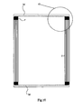
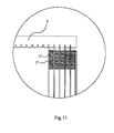
- Fig. 10 is a structural schematic view of the conventional heat exchanger and Fig. 11 is an enlarged view of Portion G' in Fig. 10 .
- the headers 3a' and 3b are disposed horizontally, parallel to and spaced from each other, and the tubes 2' are disposed vertically and parallel to each other between the headers 3a' and 3b', in which fins 1' are disposed between adjacent tubes 2' respectively.
- the conventional disposition manners of the headers and tubes are not suitable for heat exchangers of some types such as prolate type (that is, heat exchanger having a length greater than a height thereof).
- the headers should be very long such that the manufacturing costs thereof are high, and it is difficult to achieve a uniform distribution of the refrigerant. Since the headers do not participate ventilation and heat transfer, the longer the headers, the larger the area blocking the air flow, thus decreasing the effective heat-transfer area.
- the tubes are short in length and large in number, that is, the number of the flow path of the refrigerant is large, so that the flow speed of the refrigerant in the tubes is low, thus causing poor heat-transfer performance.
- the headers are disposed vertically and the tubes are disposed horizontally between the headers conventionally, thus decreasing the length of the headers, increasing the length of the tubes and decreasing the number of the tubes.
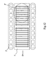
- the conventional heat exchanger of prolate type with vertically disposed headers and horizontally disposed tubes employs conventional fins, there are some problems with the drainage of the condensation water. For example, as shown in Fig. 12 , if the air is blown along the direction D', due to the surface tension of the condensation water, most condensation water will be accumulated at the leeward side (i.e. region F' shown in Fig. 12 of the heat exchanger) and can be not drained smoothly.
- an object of the present invention is to provide a fin for a heat exchanger, in which the water drainage performance of the fin is improved.
- an embodiment of the present invention provides a fin, comprising: straight segments, and substantially-circular arc segments connected with the straight segments in turn along a longitudinal direction such that the substantially-circular arc segments form wave crests and wave troughs of the fin respectively, in which the fin is divided in a lateral direction into a first end portion, in which a second end portion, and an intermediate portion between the first and second end portions, each of the substantially-circular arc segments at least forming the wave troughs in the first end portion is separated from a substantially-circular arc segment of a corresponding intermediate portion via a longitudinal slot, and in which a top of each of the substantially-circular arc segments at least forming the wave troughs in the first end portion is formed with a lateral slot along the lateral direction such that each of the substantially-circular arc segments at least forming the wave troughs in the first end portion is divided into a first straight portion and a second straight portion separated from each other.
- the first straight portion and the straight segment connected therewith may be in the same plane and the second straight portion and the straight segment connected therewith may be in the same plane as well, and when the fin is disposed between adjacent tubes of a heat exchanger, one end of the fin may be extended beyond the tubes in the lateral direction, so that the condensation water may easily flow downwardly along the first and second straight portions and the straight segments to drop off the fin and may not be accumulated on the fin, thus improving the water drainage performance of the fin.
- each of the substantially-circular arc segments at least forming the wave troughs in the second end portion is separated from a substantially-circular arc segment of a corresponding intermediate portion via the longitudinal slot, and a top of each of the substantially-circular arc segments at least forming the wave troughs in the second end portion is formed with the lateral slot along the lateral direction such that each of the substantially-circular arc segments at least forming the wave troughs in the second end portion is divided into a first straight portion and a second straight portion separated from each other.
- each of the substantially-circular arc segments at least forming the wave troughs in the second end portion is divided into the first straight portion and the second straight portion, the first straight portion and the straight segment connected therewith may be in the same plane and the second straight portion and the straight segment connected therewith may be in the same plane as well, and when the fin is disposed between adjacent tubes of a heat exchanger, the condensation water may easily flow downwardly along the first and second straight portions and the straight segments to drop off the fin and may not be accumulated on the fin, thus further improving the water drainage performance of the fin.
- each of the substantially-circular arc segments forming the wave crests and wave troughs in the first and second end portions is separated from a substantially-circular arc segment of a corresponding intermediate portion via the longitudinal slot, and a top of each of the substantially-circular arc segments forming the wave crests and the wave troughs of the first and second end portions is formed with a lateral slot along the lateral direction such that each substantially-circular arc segment of the first and second end portions is divided into the first straight portion and the second straight portion separated from each other.
- a substantially-circular arc transition segment is connected between adjacent straight segment and substantially-circular, in which R> r, where R is a radius of the substantially-circular arc segment and r is a radius of the substantially-circular arc transition segment.
- the central angle ⁇ of the substantially-circular arc segment is in a range of about 30° to about 170°. Therefore, the manufacture of the fin is more convenient.
- each straight segment is formed with a window. Therefore, the heat-transfer coefficient may be further improved.
- an embodiment of the present invention provides a heat exchanger, comprising: a first header disposed vertically; a second header disposed vertically and spaced apart from the first header; a plurality of tubes, two ends of each flat tube being connected and communicated with the first and second headers respectively; and a plurality of fins, each of which is disposed between adjacent tubes, and a first end portion of each fin extended out from a first side of the adjacent tubes in a lateral direction, wherein each fin comprises: straight segments; and substantially-circular arc segments connected with the straight segments in turn along a longitudinal direction such that the substantially-circular arc segments form wave crests and wave troughs of the fin respectively, wherein the fin is divided in a lateral direction into a first end portion, a second end portion, and an intermediate portion between the first and second end portions, wherein each of the substantially-circular arc segments at least forming the wave troughs in the first end portion is separated from a substantially-circular
- a second end portion of each fin is extended out from a second side opposite to the first side of the adjacent tubes in the lateral direction. Therefore, the water drainage performance of heat exchanger may be further improved and it is not necessary to consider the air blowing direction during mounting.
- the heat exchanger according to the embodiment of the invention also has other advantages described above with reference to the fin.
- relative terms such as “longitudinal”, “lateral”, “right”, “left”, “lower”, “upper”, “horizontal”, “vertical”, “above”, “below”, “up”, “top”, “bottom” as well as derivative thereof (e.g., “horizontally”, “vertically”, “downwardly”, “upwardly”, etc.) should be construed to refer to the orientation as then described or as shown in the drawings under discussion. These relative terms are for convenience of description and do not require that the present invention be constructed or operated in a particular orientation.
- the fin 1 is substantially corrugated, and comprises straight segments 11, and substantially-circular arc segments 12 connected with the straight segments 11 in turn along a longitudinal direction B, in which the substantially-circular arc segments 12 form wave crests and wave troughs of the fin 1 respectively.
- the fin 1 is divided in a lateral direction C into a first end portion 112, a second end portion 114, and an intermediate portion 113 between the first and second end portions 112, 114.
- the width of the first end portion 112 in the lateral direction C is S1
- the width of the second end portion 114 in the lateral direction C is S2.
- S1, S2 and the width of the intermediate portion 113 in the lateral direction C may be determined according to the specific applications and may be not particularly limited in the present invention.
- Each of the substantially-circular arc segments 12 at least forming the wave troughs in the first end portion 112 and a substantially-circular arc segment 12 of the corresponding intermediate portion 113, are split from each other in the up and down direction in Fig. 1 .
- each of the substantially-circular arc segments 12 at least forming the wave troughs in the first end portion 112 is separated from a substantially-circular arc segment 12 of the corresponding intermediate portion 113 via a longitudinal slot 111 extended downwardly to the straight segments 11 as shown in Fig. 1 .
- a lateral slot 110 is formed along the lateral direction C in a top of each of the substantially-circular arc segments 12 at least forming the wave troughs in the first end portion 112, and the lateral slot 110 is extended through the whole first end portion 112, such that each of the substantially-circular arc segments 12 at least forming the wave troughs in the first end portion 112 is divided into a first straight portion 12a and a second straight portion 12b separated from each other.
- the first straight portion 12a and the straight segment 11 connected to the first straight portion 12a are in the same plane, and the second straight portion 12b and the straight segment 11 connected to the second straight portion 12b are in the same plane as well, as shown in Fig. 1 .
- the substantially-circular arc segment 12 of the corresponding intermediate portion 113 is still substantially-circular arcuate.
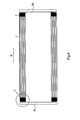
- the first end portion 112 of the fin 1 may be extended out from a first side of the adjacent tubes 2 (i.e. the right side in Fig. 8 ) along the lateral direction C, that is, the first end portion 112 of the fin 1 may be extended beyond the tubes 2 in the lateral direction C.
- each of the substantially-circular arc segments 12 at least forming the wave troughs in the first end portion 112 is divided into the first straight portion 12a and the second straight portion 12b, the surface tension of the condensation water is destroyed, so that when the air is blown along a direction D, the condensation water may not be accumulated at Area F of the fin 1, and may easily flow downwardly along the straight segments 11, and the first and second straight portions 12a, 12b to drop off the fin 1, thus improving the water drainage performance of the fin 1.
- each of the substantially-circular arc segments 12 at least forming the wave crests in the first end portion 112 is also divided into a first straight portion 12a and a second straight portion 12b via the longitudinal slot 111 and the lateral slot 110, such that when the fin 1 is disposed between adjacent tubes 2, the surface tension of the condensation water is destroyed by the first straight portion 12a and the second straight portion 12b, and the condensation water may easily flow downwardly along the first and second straight portions 12a, 12b of the substantially-circular arc segments 12 forming the wave crests, the straight segments 11, and the first and second straight portions 12a, 12b of the substantially-circular arc segments 12 forming the wave troughs, so as to drop off the fin 1, thus further reducing the possibility of the accumulating of the condensation water in Area F of the fin 1 and improving the water drainage performance of the fin 1.
- each of the substantially-circular arc segments 12 at least forming the wave troughs in the second end portion 114 of the fin 1 is also divided into a first straight portion 12a and a second straight portion 12b via the longitudinal slot 111 and the lateral slot 110.
- each of the substantially-circular arc segments 12 at least forming the wave crests in the second end portion 114 is also divided into a first straight portion 12a and a second straight portion 12b via the longitudinal slot 111 and the lateral slot 110.
- the second end portion 114 may be extended out from a second side of the tubes 2 (i.e. the left side in Fig. 8 ) along the lateral direction C, that is, the second end portion 114 of the fin 1 may be extended beyond the tubes 2 in the lateral direction C. Because each of the substantially-circular arc segments 12 forming the wave troughs or both the wave troughs and the wave crests in the second end portion 114 is divided into the first straight portion 12a and the second straight portion 12b, the surface tension of the condensation water is destroyed. For example, when air is blown along a direction opposite to the direction D (i.e. the leftward direction in Fig.
- the condensation water may not be accumulated in an area symmetrical to Area F of the fin 1, and may easily flow downwardly along the first and second straight portions 12a, 12b of the second end portion 114 and the straight segments 11 to drop off the fin 1, thus further improving the water drainage performance of the fin 1.
- each of the substantially-circular arc segments 12 forming the wave troughs or both the wave troughs and the wave crests in both the first end portion 112 and the second end portion 114 of the fin 1 is divided into the first straight portion 12a and the second straight portion 12b, and when the fin 1 is disposed between adjacent tubes 2, both the first end portion 112 and the second end portion 114 are extended out from the two sides of the tubes 2 along the lateral direction C respectively, it is not necessary to consider the air blowing direction D during mounting, thus improving the mounting efficiency and the water drainage performance of the fin 1.
- adjacent straight segment 11 and substantially-circular arc segment 12 are connected via a substantially-circular arc transition segment 13, in which R> r, where, R is a radius of the substantially-circular arc segment (its centre of circle is O1) and r is a radius of the substantially-circular arc transition segment (its centre of circle is 02).
- each end of one substantially-circular arc segment 12 is connected with an end of one substantially-circular arc transition segment 13, and the other end of the substantially-circular arc transition segment 13 is connected with an end of another straight segment 11, and then the other end of the another straight segment 11 is connected with another substantially-circular arc transition segment 13, thus forming a substantially corrugated fin 1 extending along the longitudinal direction B.
- two straight segment 11, two substantially-circular arc segment 12 and four substantially-circular arc transition segment 13 form one cycle of the fin 1, and one cycle length of the fin 1 is P.
- the fin 1 may be made, for example, by rolling metal foil. It may be understood by those skilled in the art that the cycle number of the fin 1 may be determined based on specific requirements, and is not particularly limited in the invention.
- Areas A may be substantially rectangular or square after welding.
- the compressed distance of the substantially-circular arc segment 12 is N (i. e. the chordal height of the substantially-circular arc segment 12).
- the compressed distance N is controlled within 0.01-0.1 mm, i.e. 0.01 mm ⁇ R ( 1-cos( ⁇ /2) ) ⁇ 0.1 mm, in which R is the radius of the substantially-circular arc segment 12, and ⁇ is the central angle of the substantially-circular arc segment 12.
- the central angle ⁇ of the substantially-circular arc segment 12 is set in a range of about 30° to about 170°.
Landscapes
- Engineering & Computer Science (AREA)
- Physics & Mathematics (AREA)
- Thermal Sciences (AREA)
- Mechanical Engineering (AREA)
- General Engineering & Computer Science (AREA)
- Geometry (AREA)
- Heat-Exchange Devices With Radiators And Conduit Assemblies (AREA)
Applications Claiming Priority (1)
| Application Number | Priority Date | Filing Date | Title |
|---|---|---|---|
| CN2009101623884A CN101619950B (zh) | 2009-08-13 | 2009-08-13 | 翅片和具有该翅片的换热器 |
Publications (3)
| Publication Number | Publication Date |
|---|---|
| EP2295919A2 true EP2295919A2 (de) | 2011-03-16 |
| EP2295919A3 EP2295919A3 (de) | 2014-03-26 |
| EP2295919B1 EP2295919B1 (de) | 2015-06-17 |
Family
ID=41513301
Family Applications (1)
| Application Number | Title | Priority Date | Filing Date |
|---|---|---|---|
| EP10007986.2A Active EP2295919B1 (de) | 2009-08-13 | 2010-07-30 | Lamelle und Wärmetauscher damit |
Country Status (3)
| Country | Link |
|---|---|
| US (1) | US20110036550A1 (de) |
| EP (1) | EP2295919B1 (de) |
| CN (1) | CN101619950B (de) |
Families Citing this family (22)
| Publication number | Priority date | Publication date | Assignee | Title |
|---|---|---|---|---|
| JP5320846B2 (ja) * | 2008-06-20 | 2013-10-23 | ダイキン工業株式会社 | 熱交換器 |
| JP4988015B2 (ja) * | 2010-07-20 | 2012-08-01 | シャープ株式会社 | 熱交換器及びそれを搭載した空気調和機 |
| CN103238038B (zh) * | 2010-08-24 | 2016-03-16 | 开利公司 | 微通道热交换器鳍片 |
| KR20120044847A (ko) * | 2010-10-28 | 2012-05-08 | 삼성전자주식회사 | 열교환기 및 그 핀 |
| US20140137592A1 (en) * | 2011-07-14 | 2014-05-22 | Panasonic Corporation | Outdoor heat exchanger, and air conditioning device for vehicle |
| JP5246322B2 (ja) * | 2011-12-14 | 2013-07-24 | ダイキン工業株式会社 | 熱交換器 |
| ES2627555T3 (es) * | 2013-02-13 | 2017-07-28 | Carrier Corporation | Intercambiador de calor con tubos aplanados y múltiples bancos |
| KR102218301B1 (ko) * | 2013-07-30 | 2021-02-22 | 삼성전자주식회사 | 열교환기 및 그 코르게이트 핀 |
| US10539374B2 (en) * | 2014-04-16 | 2020-01-21 | Sanhua (Hangzhou) Micro Channel Heat Exchanger Co., Ltd. | Fin and bending type heat exchanger having the fin |
| CN103913088B (zh) * | 2014-04-16 | 2016-04-13 | 杭州三花微通道换热器有限公司 | 翅片和具有该翅片的折弯式换热器 |
| US11585609B2 (en) * | 2014-05-06 | 2023-02-21 | Sanhua (Hangzhou) Micro Channel Heat Exchanger Co., Ltd. | Bent heat exchanger |
| US10197313B2 (en) * | 2014-05-09 | 2019-02-05 | Samwon Industrial Co., Ltd. | Condenser for refrigerator |
| CN104089517B (zh) * | 2014-07-18 | 2016-08-17 | 丹佛斯微通道换热器(嘉兴)有限公司 | 用于换热器的翅片和具有该翅片的换热器 |
| KR20170015146A (ko) * | 2015-07-31 | 2017-02-08 | 엘지전자 주식회사 | 열교환기 |
| US11041676B2 (en) * | 2015-07-31 | 2021-06-22 | Lg Electronics Inc. | Heat exchanger |
| CN105180706A (zh) * | 2015-09-25 | 2015-12-23 | 山东同创汽车散热装置股份有限公司 | 一种应用于重型卡车的褶皱型翅片 |
| CN110741217B (zh) * | 2017-06-12 | 2021-11-09 | 株式会社电装 | 热交换器和波纹翅片 |
| CN110595250B (zh) * | 2018-12-29 | 2025-03-21 | 杭州三花微通道换热器有限公司 | 换热器 |
| FR3106000B1 (fr) * | 2020-01-03 | 2022-01-14 | Valeo Systemes Thermiques | Échangeur de chaleur à tubes comportant des intercalaires |
| US12078431B2 (en) * | 2020-10-23 | 2024-09-03 | Carrier Corporation | Microchannel heat exchanger for a furnace |
| CN112683085A (zh) * | 2021-01-11 | 2021-04-20 | 南宁市安和机械设备有限公司 | 一种采用错位打点管制成的工程水散热器 |
| FR3158150B1 (fr) * | 2024-01-08 | 2026-01-02 | Valeo Systemes Thermiques | Intercalaire ondulé pour échangeur de chaleur |
Family Cites Families (17)
| Publication number | Priority date | Publication date | Assignee | Title |
|---|---|---|---|---|
| US2970812A (en) * | 1956-06-14 | 1961-02-07 | Richard W Kritzer | Drum type heat exchanger |
| US3228367A (en) * | 1962-12-20 | 1966-01-11 | Borg Warner | Method of manufacturing a heat exchanger |
| JPS5918179U (ja) * | 1982-07-26 | 1984-02-03 | カルソニックカンセイ株式会社 | エバポレ−タ |
| US5246064A (en) * | 1986-07-29 | 1993-09-21 | Showa Aluminum Corporation | Condenser for use in a car cooling system |
| JP2949963B2 (ja) * | 1991-10-18 | 1999-09-20 | 株式会社デンソー | コルゲートルーバフィン型熱交換器 |
| JP3814846B2 (ja) * | 1994-12-26 | 2006-08-30 | 株式会社デンソー | コルゲートフィン用成形ローラ及びコルゲートフィン成形方法 |
| US5787972A (en) * | 1997-08-22 | 1998-08-04 | General Motors Corporation | Compression tolerant louvered heat exchanger fin |
| US6074507A (en) * | 1998-01-09 | 2000-06-13 | Corrugating Roll Corporation | Corrugating roll with improved flute profile |
| JP2000193388A (ja) * | 1998-12-22 | 2000-07-14 | Denso Corp | コルゲートフィン及びその製造方法 |
| JP4207331B2 (ja) * | 1999-09-29 | 2009-01-14 | 株式会社デンソー | 複式熱交換器 |
| DE10235038A1 (de) * | 2002-07-31 | 2004-02-12 | Behr Gmbh & Co. | Flachrohr-Wärmeübertrager |
| JP4300508B2 (ja) * | 2002-12-25 | 2009-07-22 | 株式会社ティラド | 熱交換器用プレートフィンおよび熱交換器コア |
| JP2004251554A (ja) * | 2003-02-20 | 2004-09-09 | Matsushita Electric Ind Co Ltd | ヒートポンプ用室外熱交換器 |
| DE102004012796A1 (de) * | 2003-03-19 | 2004-11-11 | Denso Corp., Kariya | Wärmetauscher und Wärmeübertragungselement mit symmetrischen Winkelabschnitten |
| CN101040163A (zh) * | 2004-10-13 | 2007-09-19 | 昭和电工株式会社 | 蒸发器 |
| JP2007212009A (ja) * | 2006-02-07 | 2007-08-23 | Sanden Corp | 熱交換器 |
| JP2007232246A (ja) * | 2006-02-28 | 2007-09-13 | Denso Corp | 熱交換器 |
-
2009
- 2009-08-13 CN CN2009101623884A patent/CN101619950B/zh active Active
-
2010
- 2010-07-30 EP EP10007986.2A patent/EP2295919B1/de active Active
- 2010-08-10 US US12/806,323 patent/US20110036550A1/en not_active Abandoned
Non-Patent Citations (1)
| Title |
|---|
| None |
Also Published As
| Publication number | Publication date |
|---|---|
| EP2295919B1 (de) | 2015-06-17 |
| CN101619950A (zh) | 2010-01-06 |
| US20110036550A1 (en) | 2011-02-17 |
| CN101619950B (zh) | 2011-05-04 |
| EP2295919A3 (de) | 2014-03-26 |
Similar Documents
| Publication | Publication Date | Title |
|---|---|---|
| EP2295919B1 (de) | Lamelle und Wärmetauscher damit | |
| US8656986B2 (en) | Fin, heat exchanger and heat exchanger assembly | |
| EP2369285B1 (de) | Wärmetauscher | |
| JP5320846B2 (ja) | 熱交換器 | |
| US9671177B2 (en) | Heat exchanger, method for fabricating heat exchanger, and air-conditioning apparatus | |
| EP2447656B1 (de) | Wärmetauscher mit transversalen geschlitzten Rippen | |
| CN106918261B (zh) | 一种翅片及热交换器 | |
| US20100243224A1 (en) | Fin for heat exchanger and heat exchanger using the fin | |
| JP2010019534A (ja) | 熱交換器 | |
| CN101738126A (zh) | 换热器及其翅片 | |
| JP7660665B2 (ja) | 熱交換器および冷凍サイクル装置 | |
| JP2013245884A (ja) | フィンチューブ熱交換器 | |
| CN101672554B (zh) | 具有改善排水性能的换热器 | |
| CN204313688U (zh) | 翅片和具有该翅片的换热器 | |
| JPWO2012102053A1 (ja) | フィンチューブ型熱交換器 | |
| CN214333108U (zh) | 换热器和具有该换热器的空调系统 | |
| EP3850292B1 (de) | Wärmetauscher und klimaanlage damit | |
| WO2013161290A1 (ja) | フィンチューブ熱交換器 | |
| JP6719657B2 (ja) | 熱交換器および冷凍サイクル装置 | |
| CN107843031B (zh) | 微通道换热器 | |
| KR101225597B1 (ko) | 열교환기용 루버 핀 | |
| EP4300026B1 (de) | Wärmetauschrippe, wärmetauscher und wärmepumpensystem | |
| JP3957021B2 (ja) | 熱交換器 | |
| JP2002090083A (ja) | 熱交換器 | |
| JPWO2021234957A5 (de) |
Legal Events
| Date | Code | Title | Description |
|---|---|---|---|
| PUAI | Public reference made under article 153(3) epc to a published international application that has entered the european phase |
Free format text: ORIGINAL CODE: 0009012 |
|
| AK | Designated contracting states |
Kind code of ref document: A2 Designated state(s): AL AT BE BG CH CY CZ DE DK EE ES FI FR GB GR HR HU IE IS IT LI LT LU LV MC MK MT NL NO PL PT RO SE SI SK SM TR |
|
| AX | Request for extension of the european patent |
Extension state: BA ME RS |
|
| RIN1 | Information on inventor provided before grant (corrected) |
Inventor name: HUANG, LIN-JIE Inventor name: JIANLONG, JIANG |
|
| RAP1 | Party data changed (applicant data changed or rights of an application transferred) |
Owner name: SANHUA HOLDING GROUP CO., LTD. Owner name: DANFOSS A/S |
|
| PUAL | Search report despatched |
Free format text: ORIGINAL CODE: 0009013 |
|
| AK | Designated contracting states |
Kind code of ref document: A3 Designated state(s): AL AT BE BG CH CY CZ DE DK EE ES FI FR GB GR HR HU IE IS IT LI LT LU LV MC MK MT NL NO PL PT RO SE SI SK SM TR |
|
| AX | Request for extension of the european patent |
Extension state: BA ME RS |
|
| RIC1 | Information provided on ipc code assigned before grant |
Ipc: F28F 1/12 20060101AFI20140218BHEP Ipc: F28F 17/00 20060101ALI20140218BHEP |
|
| 17P | Request for examination filed |
Effective date: 20140809 |
|
| RBV | Designated contracting states (corrected) |
Designated state(s): AL AT BE BG CH CY CZ DE DK EE ES FI FR GB GR HR HU IE IS IT LI LT LU LV MC MK MT NL NO PL PT RO SE SI SK SM TR |
|
| RIC1 | Information provided on ipc code assigned before grant |
Ipc: F28F 17/00 20060101ALI20140929BHEP Ipc: F28F 1/12 20060101AFI20140929BHEP |
|
| GRAP | Despatch of communication of intention to grant a patent |
Free format text: ORIGINAL CODE: EPIDOSNIGR1 |
|
| INTG | Intention to grant announced |
Effective date: 20141209 |
|
| GRAS | Grant fee paid |
Free format text: ORIGINAL CODE: EPIDOSNIGR3 |
|
| GRAA | (expected) grant |
Free format text: ORIGINAL CODE: 0009210 |
|
| AK | Designated contracting states |
Kind code of ref document: B1 Designated state(s): AL AT BE BG CH CY CZ DE DK EE ES FI FR GB GR HR HU IE IS IT LI LT LU LV MC MK MT NL NO PL PT RO SE SI SK SM TR |
|
| RAP1 | Party data changed (applicant data changed or rights of an application transferred) |
Owner name: SANHUA (HANGZHOU) MICRO CHANNEL HEAT EXCHANGER CO. Owner name: SANHUA HOLDING GROUP CO., LTD. Owner name: DANFOSS A/S |
|
| REG | Reference to a national code |
Ref country code: GB Ref legal event code: FG4D |
|
| REG | Reference to a national code |
Ref country code: CH Ref legal event code: EP |
|
| RAP2 | Party data changed (patent owner data changed or rights of a patent transferred) |
Owner name: SANHUA (HANGZHOU) MICRO CHANNEL HEAT EXCHANGER CO. Owner name: DANFOSS A/S |
|
| REG | Reference to a national code |
Ref country code: DE Ref legal event code: R082 Ref document number: 602010025227 Country of ref document: DE Representative=s name: PATENTANWAELTE DR. KNOBLAUCH PARTGMBB, DE |
|
| REG | Reference to a national code |
Ref country code: AT Ref legal event code: REF Ref document number: 732181 Country of ref document: AT Kind code of ref document: T Effective date: 20150715 |
|
| REG | Reference to a national code |
Ref country code: IE Ref legal event code: FG4D |
|
| REG | Reference to a national code |
Ref country code: DE Ref legal event code: R096 Ref document number: 602010025227 Country of ref document: DE |
|
| PG25 | Lapsed in a contracting state [announced via postgrant information from national office to epo] |
Ref country code: HR Free format text: LAPSE BECAUSE OF FAILURE TO SUBMIT A TRANSLATION OF THE DESCRIPTION OR TO PAY THE FEE WITHIN THE PRESCRIBED TIME-LIMIT Effective date: 20150617 Ref country code: NO Free format text: LAPSE BECAUSE OF FAILURE TO SUBMIT A TRANSLATION OF THE DESCRIPTION OR TO PAY THE FEE WITHIN THE PRESCRIBED TIME-LIMIT Effective date: 20150917 Ref country code: LT Free format text: LAPSE BECAUSE OF FAILURE TO SUBMIT A TRANSLATION OF THE DESCRIPTION OR TO PAY THE FEE WITHIN THE PRESCRIBED TIME-LIMIT Effective date: 20150617 Ref country code: FI Free format text: LAPSE BECAUSE OF FAILURE TO SUBMIT A TRANSLATION OF THE DESCRIPTION OR TO PAY THE FEE WITHIN THE PRESCRIBED TIME-LIMIT Effective date: 20150617 |
|
| REG | Reference to a national code |
Ref country code: AT Ref legal event code: MK05 Ref document number: 732181 Country of ref document: AT Kind code of ref document: T Effective date: 20150617 |
|
| REG | Reference to a national code |
Ref country code: LT Ref legal event code: MG4D Ref country code: NL Ref legal event code: MP Effective date: 20150617 |
|
| PG25 | Lapsed in a contracting state [announced via postgrant information from national office to epo] |
Ref country code: LV Free format text: LAPSE BECAUSE OF FAILURE TO SUBMIT A TRANSLATION OF THE DESCRIPTION OR TO PAY THE FEE WITHIN THE PRESCRIBED TIME-LIMIT Effective date: 20150617 Ref country code: BG Free format text: LAPSE BECAUSE OF FAILURE TO SUBMIT A TRANSLATION OF THE DESCRIPTION OR TO PAY THE FEE WITHIN THE PRESCRIBED TIME-LIMIT Effective date: 20150917 Ref country code: GR Free format text: LAPSE BECAUSE OF FAILURE TO SUBMIT A TRANSLATION OF THE DESCRIPTION OR TO PAY THE FEE WITHIN THE PRESCRIBED TIME-LIMIT Effective date: 20150918 |
|
| PG25 | Lapsed in a contracting state [announced via postgrant information from national office to epo] |
Ref country code: EE Free format text: LAPSE BECAUSE OF FAILURE TO SUBMIT A TRANSLATION OF THE DESCRIPTION OR TO PAY THE FEE WITHIN THE PRESCRIBED TIME-LIMIT Effective date: 20150617 |
|
| PG25 | Lapsed in a contracting state [announced via postgrant information from national office to epo] |
Ref country code: PL Free format text: LAPSE BECAUSE OF FAILURE TO SUBMIT A TRANSLATION OF THE DESCRIPTION OR TO PAY THE FEE WITHIN THE PRESCRIBED TIME-LIMIT Effective date: 20150617 Ref country code: CZ Free format text: LAPSE BECAUSE OF FAILURE TO SUBMIT A TRANSLATION OF THE DESCRIPTION OR TO PAY THE FEE WITHIN THE PRESCRIBED TIME-LIMIT Effective date: 20150617 Ref country code: SK Free format text: LAPSE BECAUSE OF FAILURE TO SUBMIT A TRANSLATION OF THE DESCRIPTION OR TO PAY THE FEE WITHIN THE PRESCRIBED TIME-LIMIT Effective date: 20150617 Ref country code: ES Free format text: LAPSE BECAUSE OF FAILURE TO SUBMIT A TRANSLATION OF THE DESCRIPTION OR TO PAY THE FEE WITHIN THE PRESCRIBED TIME-LIMIT Effective date: 20150617 Ref country code: RO Free format text: LAPSE BECAUSE OF NON-PAYMENT OF DUE FEES Effective date: 20150617 Ref country code: PT Free format text: LAPSE BECAUSE OF FAILURE TO SUBMIT A TRANSLATION OF THE DESCRIPTION OR TO PAY THE FEE WITHIN THE PRESCRIBED TIME-LIMIT Effective date: 20151019 Ref country code: IS Free format text: LAPSE BECAUSE OF FAILURE TO SUBMIT A TRANSLATION OF THE DESCRIPTION OR TO PAY THE FEE WITHIN THE PRESCRIBED TIME-LIMIT Effective date: 20151017 Ref country code: AT Free format text: LAPSE BECAUSE OF FAILURE TO SUBMIT A TRANSLATION OF THE DESCRIPTION OR TO PAY THE FEE WITHIN THE PRESCRIBED TIME-LIMIT Effective date: 20150617 |
|
| REG | Reference to a national code |
Ref country code: CH Ref legal event code: PL |
|
| REG | Reference to a national code |
Ref country code: DE Ref legal event code: R097 Ref document number: 602010025227 Country of ref document: DE |
|
| PG25 | Lapsed in a contracting state [announced via postgrant information from national office to epo] |
Ref country code: MC Free format text: LAPSE BECAUSE OF FAILURE TO SUBMIT A TRANSLATION OF THE DESCRIPTION OR TO PAY THE FEE WITHIN THE PRESCRIBED TIME-LIMIT Effective date: 20150617 |
|
| REG | Reference to a national code |
Ref country code: IE Ref legal event code: MM4A |
|
| PLBE | No opposition filed within time limit |
Free format text: ORIGINAL CODE: 0009261 |
|
| STAA | Information on the status of an ep patent application or granted ep patent |
Free format text: STATUS: NO OPPOSITION FILED WITHIN TIME LIMIT |
|
| PG25 | Lapsed in a contracting state [announced via postgrant information from national office to epo] |
Ref country code: CH Free format text: LAPSE BECAUSE OF NON-PAYMENT OF DUE FEES Effective date: 20150731 Ref country code: IT Free format text: LAPSE BECAUSE OF FAILURE TO SUBMIT A TRANSLATION OF THE DESCRIPTION OR TO PAY THE FEE WITHIN THE PRESCRIBED TIME-LIMIT Effective date: 20150617 Ref country code: LI Free format text: LAPSE BECAUSE OF NON-PAYMENT OF DUE FEES Effective date: 20150731 Ref country code: DK Free format text: LAPSE BECAUSE OF FAILURE TO SUBMIT A TRANSLATION OF THE DESCRIPTION OR TO PAY THE FEE WITHIN THE PRESCRIBED TIME-LIMIT Effective date: 20150617 |
|
| 26N | No opposition filed |
Effective date: 20160318 |
|
| GBPC | Gb: european patent ceased through non-payment of renewal fee |
Effective date: 20150917 |
|
| REG | Reference to a national code |
Ref country code: FR Ref legal event code: PLFP Year of fee payment: 7 |
|
| PG25 | Lapsed in a contracting state [announced via postgrant information from national office to epo] |
Ref country code: GB Free format text: LAPSE BECAUSE OF NON-PAYMENT OF DUE FEES Effective date: 20150917 Ref country code: IE Free format text: LAPSE BECAUSE OF NON-PAYMENT OF DUE FEES Effective date: 20150730 |
|
| PG25 | Lapsed in a contracting state [announced via postgrant information from national office to epo] |
Ref country code: SI Free format text: LAPSE BECAUSE OF FAILURE TO SUBMIT A TRANSLATION OF THE DESCRIPTION OR TO PAY THE FEE WITHIN THE PRESCRIBED TIME-LIMIT Effective date: 20150617 |
|
| PG25 | Lapsed in a contracting state [announced via postgrant information from national office to epo] |
Ref country code: BE Free format text: LAPSE BECAUSE OF FAILURE TO SUBMIT A TRANSLATION OF THE DESCRIPTION OR TO PAY THE FEE WITHIN THE PRESCRIBED TIME-LIMIT Effective date: 20150617 |
|
| PG25 | Lapsed in a contracting state [announced via postgrant information from national office to epo] |
Ref country code: MT Free format text: LAPSE BECAUSE OF FAILURE TO SUBMIT A TRANSLATION OF THE DESCRIPTION OR TO PAY THE FEE WITHIN THE PRESCRIBED TIME-LIMIT Effective date: 20150617 |
|
| PG25 | Lapsed in a contracting state [announced via postgrant information from national office to epo] |
Ref country code: SM Free format text: LAPSE BECAUSE OF FAILURE TO SUBMIT A TRANSLATION OF THE DESCRIPTION OR TO PAY THE FEE WITHIN THE PRESCRIBED TIME-LIMIT Effective date: 20150617 Ref country code: HU Free format text: LAPSE BECAUSE OF FAILURE TO SUBMIT A TRANSLATION OF THE DESCRIPTION OR TO PAY THE FEE WITHIN THE PRESCRIBED TIME-LIMIT; INVALID AB INITIO Effective date: 20100730 |
|
| PG25 | Lapsed in a contracting state [announced via postgrant information from national office to epo] |
Ref country code: CY Free format text: LAPSE BECAUSE OF FAILURE TO SUBMIT A TRANSLATION OF THE DESCRIPTION OR TO PAY THE FEE WITHIN THE PRESCRIBED TIME-LIMIT Effective date: 20150617 Ref country code: NL Free format text: LAPSE BECAUSE OF FAILURE TO SUBMIT A TRANSLATION OF THE DESCRIPTION OR TO PAY THE FEE WITHIN THE PRESCRIBED TIME-LIMIT Effective date: 20150617 Ref country code: SE Free format text: LAPSE BECAUSE OF FAILURE TO SUBMIT A TRANSLATION OF THE DESCRIPTION OR TO PAY THE FEE WITHIN THE PRESCRIBED TIME-LIMIT Effective date: 20150617 |
|
| REG | Reference to a national code |
Ref country code: FR Ref legal event code: PLFP Year of fee payment: 8 |
|
| PG25 | Lapsed in a contracting state [announced via postgrant information from national office to epo] |
Ref country code: TR Free format text: LAPSE BECAUSE OF FAILURE TO SUBMIT A TRANSLATION OF THE DESCRIPTION OR TO PAY THE FEE WITHIN THE PRESCRIBED TIME-LIMIT Effective date: 20150617 |
|
| PG25 | Lapsed in a contracting state [announced via postgrant information from national office to epo] |
Ref country code: LU Free format text: LAPSE BECAUSE OF NON-PAYMENT OF DUE FEES Effective date: 20150730 |
|
| PG25 | Lapsed in a contracting state [announced via postgrant information from national office to epo] |
Ref country code: MK Free format text: LAPSE BECAUSE OF FAILURE TO SUBMIT A TRANSLATION OF THE DESCRIPTION OR TO PAY THE FEE WITHIN THE PRESCRIBED TIME-LIMIT Effective date: 20150617 |
|
| REG | Reference to a national code |
Ref country code: FR Ref legal event code: PLFP Year of fee payment: 9 |
|
| REG | Reference to a national code |
Ref country code: DE Ref legal event code: R082 Ref document number: 602010025227 Country of ref document: DE Representative=s name: KEIL & SCHAAFHAUSEN PATENTANWAELTE PARTGMBB, DE Ref country code: DE Ref legal event code: R082 Ref document number: 602010025227 Country of ref document: DE Representative=s name: KEIL & SCHAAFHAUSEN PATENT- UND RECHTSANWAELTE, DE |
|
| PG25 | Lapsed in a contracting state [announced via postgrant information from national office to epo] |
Ref country code: AL Free format text: LAPSE BECAUSE OF FAILURE TO SUBMIT A TRANSLATION OF THE DESCRIPTION OR TO PAY THE FEE WITHIN THE PRESCRIBED TIME-LIMIT Effective date: 20150617 |
|
| P01 | Opt-out of the competence of the unified patent court (upc) registered |
Effective date: 20230529 |
|
| REG | Reference to a national code |
Ref country code: DE Ref legal event code: R081 Ref document number: 602010025227 Country of ref document: DE Owner name: SANHUA (HANGZHOU) MICRO CHANNEL HEAT EXCHANGER, CN Free format text: FORMER OWNERS: DANFOSS A/S, NORDBORG, DK; SANHUA (HANGZHOU) MICRO CHANNEL HEAT EXCHANGER CO. LTD., HANGZHOU, ZHEJIANG, CN |
|
| PGFP | Annual fee paid to national office [announced via postgrant information from national office to epo] |
Ref country code: DE Payment date: 20250723 Year of fee payment: 16 |
|
| PGFP | Annual fee paid to national office [announced via postgrant information from national office to epo] |
Ref country code: FR Payment date: 20250723 Year of fee payment: 16 |