EP2295921A2 - Wärmetauscher mit Dichtfläche und Spannfläche aufweisenden Anschlussabschnitt - Google Patents
Wärmetauscher mit Dichtfläche und Spannfläche aufweisenden Anschlussabschnitt Download PDFInfo
- Publication number
- EP2295921A2 EP2295921A2 EP10170777A EP10170777A EP2295921A2 EP 2295921 A2 EP2295921 A2 EP 2295921A2 EP 10170777 A EP10170777 A EP 10170777A EP 10170777 A EP10170777 A EP 10170777A EP 2295921 A2 EP2295921 A2 EP 2295921A2
- Authority
- EP
- European Patent Office
- Prior art keywords
- heat exchanger
- connection
- sealing surface
- strip
- terminal
- Prior art date
- Legal status (The legal status is an assumption and is not a legal conclusion. Google has not performed a legal analysis and makes no representation as to the accuracy of the status listed.)
- Granted
Links
Images
Classifications
-
- F—MECHANICAL ENGINEERING; LIGHTING; HEATING; WEAPONS; BLASTING
- F28—HEAT EXCHANGE IN GENERAL
- F28F—DETAILS OF HEAT-EXCHANGE AND HEAT-TRANSFER APPARATUS, OF GENERAL APPLICATION
- F28F9/00—Casings; Header boxes; Auxiliary supports for elements; Auxiliary members within casings
- F28F9/02—Header boxes; End plates
- F28F9/0246—Arrangements for connecting header boxes with flow lines
-
- F—MECHANICAL ENGINEERING; LIGHTING; HEATING; WEAPONS; BLASTING
- F16—ENGINEERING ELEMENTS AND UNITS; GENERAL MEASURES FOR PRODUCING AND MAINTAINING EFFECTIVE FUNCTIONING OF MACHINES OR INSTALLATIONS; THERMAL INSULATION IN GENERAL
- F16L—PIPES; JOINTS OR FITTINGS FOR PIPES; SUPPORTS FOR PIPES, CABLES OR PROTECTIVE TUBING; MEANS FOR THERMAL INSULATION IN GENERAL
- F16L23/00—Flanged joints
- F16L23/04—Flanged joints the flanges being connected by members tensioned in the radial plane
-
- F—MECHANICAL ENGINEERING; LIGHTING; HEATING; WEAPONS; BLASTING
- F28—HEAT EXCHANGE IN GENERAL
- F28D—HEAT-EXCHANGE APPARATUS, NOT PROVIDED FOR IN ANOTHER SUBCLASS, IN WHICH THE HEAT-EXCHANGE MEDIA DO NOT COME INTO DIRECT CONTACT
- F28D21/00—Heat-exchange apparatus not covered by any of the groups F28D1/00 - F28D20/00
- F28D2021/0019—Other heat exchangers for particular applications; Heat exchange systems not otherwise provided for
- F28D2021/008—Other heat exchangers for particular applications; Heat exchange systems not otherwise provided for for vehicles
- F28D2021/0082—Charged air coolers
-
- F—MECHANICAL ENGINEERING; LIGHTING; HEATING; WEAPONS; BLASTING
- F28—HEAT EXCHANGE IN GENERAL
- F28D—HEAT-EXCHANGE APPARATUS, NOT PROVIDED FOR IN ANOTHER SUBCLASS, IN WHICH THE HEAT-EXCHANGE MEDIA DO NOT COME INTO DIRECT CONTACT
- F28D21/00—Heat-exchange apparatus not covered by any of the groups F28D1/00 - F28D20/00
- F28D21/0001—Recuperative heat exchangers
- F28D21/0003—Recuperative heat exchangers the heat being recuperated from exhaust gases
-
- F—MECHANICAL ENGINEERING; LIGHTING; HEATING; WEAPONS; BLASTING
- F28—HEAT EXCHANGE IN GENERAL
- F28F—DETAILS OF HEAT-EXCHANGE AND HEAT-TRANSFER APPARATUS, OF GENERAL APPLICATION
- F28F2275/00—Fastening; Joining
- F28F2275/08—Fastening; Joining by clamping or clipping
Definitions
- the invention relates to a heat exchanger for heat exchange between a working fluid on the one hand and a cooling fluid on the other hand, with a heat exchanger core for implementing the heat exchange.
- the invention also relates to a heat exchanger system.
- Heat exchangers of the type mentioned are used in particular as a gas cooler in the context of a charging system for an internal combustion engine.
- Working fluid in the form of gas can be supplied as exhaust gas and / or a charge air of the internal combustion engine, compressed and cooled, the input side of the internal combustion engine again.
- Charging systems, in particular exhaust gas delivery systems of this type are used in addition to an increase in performance of the internal combustion engine and the pollutant reduction, in particular the nitrogen oxide reduction, in the exhaust gases emitted to the environment.
- a heat exchanger block has to implement the heat exchange regularly a core for separate and heat exchanging leadership the working fluid and the cooling fluid on and a core receiving, can be flowed through by the cooling fluid housing.
- a heat exchanger block To connect the heat exchanger block to a connecting line, it has hitherto been customary to provide the housing with a flange plate.
- a flange plate is usually welded to the housing and is regularly made of a high quality material, such as stainless steel.
- a connecting flange of the connecting cable is used for connection to the flange plate, possibly with a sealing element. The connecting flange is screwed regularly to the flange plate.
- connection of a heat exchanger block to the connecting line has proven itself, however, is relatively expensive.
- the welding process is laborious and can induce thermal stresses in the material, so that dimensional control is required on a regular basis.
- connecting parts of the connecting line such as a diffuser or a connecting piece of the connecting line, to be manufactured separately.
- separate tools must be available. The assembly of the connecting cable and any connecting parts of the connecting cable has to be carried out in a separate process step, as explained.
- the invention begins, whose task is to provide a heat exchanger, which can be comparatively simple and yet reliably connect to a connecting line.
- a heat exchanger should be simpler and, if possible, more cost-effectively constructed or produced.
- the object is achieved by the invention by means of a heat exchanger of the type mentioned, in which according to the invention the heat exchanger block for connection to a connecting line has an end side section arranged on the connection side with a bar having a sealing surface and a clamping surface, wherein the clamping surface as an attack surface is designed for a clamping element and the sealing surface as a contact surface for the connecting line.
- a heat exchanger according to the invention is preferably designed as a gas cooler.
- the heat exchanger block has a core for the separate and heat exchanging guidance of the working fluid and the cooling fluid and a core receiving, can be flowed through by the cooling fluid housing.
- the housing and / or the core is designed for connection to the connecting line.
- the housing and / or the core e.g. a bottom of the core - a arranged on the connection side end-side section with a bar, which has a sealing surface and a clamping surface, wherein the clamping surface is formed as a contact surface for a clamping element and the sealing surface as a contact surface for the connecting line.
- a bottom of the core receiving the flow channels is suitable for attaching the strip.
- a bottom is provided with a number of openings in which end portions of the flow channels are received.
- An opening may be formed, for example in the form of a passage for a flow channel.
- the invention is based on the consideration that the connection of a connecting line via a flange, as is customary in the prior art - in particular for certain loads in the connecting line - can be replaced by a simpler solution.
- the invention has recognized that an end-side section which is arranged on the connection side and has a strip which has a sealing surface and a clamping surface is easy to realize and nevertheless allows a secure connection of the connection line. This is especially true for a, preferably V-shaped, arrangement of the clamping surface and sealing surface. This makes it possible to press a connection surface of the connecting line onto the sealing surface of the strip simultaneously acting on the clamping surface and a terminal clamping surface of the connecting line clamping element. As a result, the connection line is safely and yet simply connected to the heat exchanger block.
- the concept of the invention for solving the problem also leads to a heat exchanger system with an aforementioned heat exchanger and a connecting line, wherein the connecting line has a arranged on the connection side end-side gate with a terminal block, which has a terminal sealing surface and a terminal clamping surface.
- the terminal clamping surface is designed as a contact surface for the clamping element and the connection sealing surface as a contact surface for the heat exchanger block.
- the tensioning element may be formed, for example, as a clamp, clamp or other suitable means for sealing against each other - that is, under tension - of the heat exchanger block and the connecting line.
- a pressing together of the sealing surface and the connection sealing surface over the clamping surface and the terminal clamping surface is made possible.
- the sealing surface of the heat exchanger block and the Ansclussdicht Chemistry the connecting line can, as far as technically feasible, without a separate Sealing gas-tight pressed together.
- a heat exchanger, in particular gas cooler is preferably suitable as a low-pressure heat exchanger.
- a low-pressure heat exchanger can be used in a low-pressure region of a charging system.
- a heat exchanger or a heat exchanger system according to the concept of the invention can also be used in a high-pressure part of a charging system.
- a connecting line in the present case, any connection part can be understood, which is useful in the context of a charging system for connection to a heat exchanger.
- a connecting line may be formed in the form of a connecting piece, in particular in the form of a connecting piece with a diffuser.
- a diffuser serves, in particular, to ensure a uniform flow of the flow channels in the core of the heat exchanger block. This becomes particularly relevant if the connection line in the remaining area has a smaller cross-section than the flow area of the arrangement of the flow channels in the core of the heat exchanger block.
- connecting lines with a comparatively large cross-section are already being used, so that a diffuser for connection to the heat exchanger block may possibly be omitted.
- the connecting line may be a supply line or a discharge line,
- the strip is preferably arranged on an end-side section of the housing arranged on the connection side. From the training has been recognized that the housing already has an advantageous stable structure and a sufficient material thickness, which is suitable for connecting a connecting cable.
- the strip in the axial alignment of the housing may advantageously be arranged behind a bottom of the heat exchanger core.
- the strip may be arranged on a terminal strip facing the distal end of the housing. In other words, the cross-section of the terminal strip is first flowed through on an input side of the heat exchanger, and then the flow of the working fluid enters the flow channels held in the bottom.
- an advantageous flow characteristic is achieved in the region of the connection of the connecting line to the heat exchanger.
- the strip can also be arranged in front of or in alignment with a bottom of the heat exchanger core.
- the strip is arranged on the outside of the heat exchanger core, in particular on the housing.
- the external arrangement avoids that an inflow cross section of the flow channels is unnecessarily reduced by the bar. Depending on the design of the bar, this can also support or exert a diffuser effect on the flow of the flow channels. This advantage is particularly suitable for a low pressure application of the heat exchanger, to make a diffuser as a separate component dispensable.
- a clamping surface and / or sealing surface can in principle be made as needed, as far as the functionality of a clamping element and a tightness of the connection point are ensured.
- the clamping surface and / or sealing surface is placed obliquely against an axis of the heat exchanger block.
- the clamping surface and the sealing surface are directed against each other.
- the clamping surface and the sealing surface can be approximately directed in the form of an inverted "V" against each other and arranged externally on the heat exchanger block or formed with the block.
- the strip may be formed integrally or integrally with the housing or a bottom of the core.
- a bar in the form of a connecting bead has proven to be advantageous.
- an outwardly directed connection bead can be produced comparatively easily as a protuberance, for example of the housing of the heat exchanger block.
- the strip may be formed in the form of a two-legged terminal board.
- an outboard port can be easily reached by an outwardly directed, twice bending the distal end of the housing.
- the two-legged connection board thereby forms an approximately V-shaped collar at the distal end of the housing or heat exchanger core.
- the strip may be formed in the form of a two-sided Ranunas.
- a two-sided connection bead is advantageously mounted in Vollmaterialausglanrung on the outside of the housing or heat exchanger core.
- the housing or the heat exchanger core is given additional stability due to the higher material accumulation.
- the clamping surface and the sealing surface can be rectified.
- this is the case when the clamping surface and the sealing surface form two sides of a wall, for example a housing wall.
- the strip is vorteihaft formed according to this development in the form of a funnel-shaped expansion of the heat exchanger core.
- the clamping surface and the sealing surface can be directed against each other and - rectified - be rectified at the terminal block, the terminal clamping surface and the connection sealing surface.
- a connection sealing surface lying on the inside of a funnel-shaped widening of the connecting line is pressed onto an outer sealing surface and thus provides the connection of the connected load.
- the roles are reversed when connecting the connecting line and the heat exchanger.
- the clamping surface and the sealing surface is rectified, while in the terminal block, the terminal clamping surface and the connection sealing surface are directed against each other.
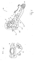
- Fig. 1 shows a heat exchanger system 100 with a heat exchanger 10 and a multi-part line 20.
- the heat exchanger 10 has a heat exchanger block 11 with a housing 12 and a heat exchanger core not shown for separate and heat exchanging guidance of a working fluid AF and a cooling fluid KF.
- the working fluid AF is supplied via the line 20 flow channels of the heat exchanger core, which are flowed around by the cooling fluid KF in a chamber of the housing 12.
- the multi-part line 20 has a diffuser 21, an expansion element 22 in the form of a bellows and a connecting piece 23, which in detail A of Fig. 1 is shown enlarged.
- the expansion element 22 and the Anschtussstutzen 23 are presently connected via a clamp 24 together.
- Other parts of the line 20, which are part of an exhaust gas recirculation system, can be connected via a flange plate 25 attached to the nozzle.
- a flange plate is also used in the prior art to connect a direct connection line or other parts of the conduit 20, such as a diffuser 21, to the heat exchanger 10.
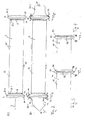
- FIG. 2 a first embodiment with reference to a schematically illustrated housing 32 of a heat exchanger block 31 shown.
- the schematically illustrated housing 32 of Fig. 2 as well as the others as part of the Fig. 3 to Fig. 7 explained housing 42, 52, 62, 72 and 82 as part of the further explained heat exchanger blocks 41, 51, 61, 71 and 81 can in the in Fig. 1 explained heat exchanger system 100 and heat exchanger 10 instead of the housing 12 shown there or heat exchanger block 11 are used.
- the heat exchanger block 31 of the Fig. 2A indicates connection to an in Fig. 2B illustrated connection line 33.1, 33.2 a arranged on the terminal side I, II end-side section with a bar, which in the embodiment of the Fig. 2 in the form of an outwardly directed V-shaped connecting bead 34.1, 34.2 is formed.
- both an input-side connecting bead 34.1 is provided for connecting a feeding connecting line 33.1 and also an output-side connecting bead 34.2 for connecting a discharging connecting line 33.2.
- Next is the case 32 are provided in an area of the heat exchanger core with outwardly directed expansion beads 35, two of which are shown here by way of example.
- the heat exchanger core not shown in detail has a number of flow channels, which are held in an inlet-side tube plate 36.1 and an outlet-side tube plate 36.2.
- a tube plate 36.1, 36.2 has for this purpose a number of flow channels corresponding number of openings 37, which in the present case as a draft, possibly with collar for improved maintenance of the flow channels, in the tube plate 36.1, 36.2 are formed.
- a connection bead 34.1, 24.2 is in accordance with the in Fig. 2 illustrated embodiment behind a tube sheet 36.1, 36.2 arranged a heat exchanger core, that is, in other words, the end-side section I, II is present outside the region of the heat exchanger core.
- a connecting bead 34.1, 34.2 has to exert its connection function on a sealing surface 38 and a clamping surface 39 which are obliquely directed against an axis A of the housing 32 and to form a V-shape obliquely against each other.
- a connecting bead 34.1, 34 2 forms with its sealing surface 38 a distal end of the housing 32 and is in alignment with the outgoing clamping surface 39 substantially with a tube plate 36.1, 36.2.
- a supply line 33.1 and discharge line 33.2 can be provided with a funnel-shaped widening 91.
- the widening 91 is formed of a thinner material than the strip of the housing 32.
- An inner connection sealing surface 92 of the widening 91 can thus be closely fitted to the sealing face 38 of the connecting bead 34.1, 34.2 attach and nestle.
- a sealing element may be provided.
- the embodiment of the widening 91 with a material thickness lower than a material thickness of the connecting bead 34.1, 34.2 is also suitable. In this way, a comparatively good material shaping of the funnel-shaped widening to the connection bead 34.1, 34.2 in the region of the connection sealing surface 92 or the sealing surface 38 is achieved.
- FIG. 3 and FIG. 4 show variations of the housing 32 with respect to the axial positioning of a terminal bead 34.1, 34.2 with respect to a tube sheet 36.1, 36.2.
- Fig. 3 shows a housing 42 of a partially illustrated heat exchanger block 41, in which a as in Fig. 2 explained educated and functioning connection bead 44 at the distal end of the housing 42 is arranged so that it is aligned with its zenith 47 between clamping surface 49 and sealing surface 48 substantially with a tube plate 46 of the heat exchanger core.
- Fig. 4 shows a housing 52 of a heat exchanger block 51, in which the terminal bead 54 is arranged at the distal end of the housing 52 so that it is aligned at the distal end with its sealing surface 58 with the tube plate 56 of the heat exchanger core.
- the region of the zenith 57 and the clamping surface 59 of the connecting bead 54 thus overlaps with a tube plate and an immediately adjoining end-side flow channel section of the heat exchanger core.
- overlaps End-side section I, II in the embodiment of the Fig. 3 half and in the embodiment of the Fig. 4 complete with an end portion of the heat exchanger core.
- Fig. 5 shows a further embodiment of a housing 62 in a heat exchanger block 61, wherein the housing 62 is in turn provided with expansion beads 65 in the region of the heat exchanger core.
- a strip formed in the form of a two-legged connecting board 64.1, 64.2 is outwardly directed and performs a function, as described with reference to the connecting bead 34.1, 34.2 in FIG Fig. 2A and Fig. 2B was explained.
- the axial arrangement of the two-legged connecting board 64.1, 64.2 with respect to a tube plate 66 corresponds to the arrangement of a connecting bead 34.1, 34.2 of Fig. 2A, Fig.
- the two-legged terminal board 64.1, 64.2 forms the distal end of the housing 62 and is aligned with its clamping surface 69 with the tube sheet 66, a sealing surface 68 is aligned with the distal end.
- the sealing surface 68 results from a single bending of the housing edge.
- the clamping surface 69 is obtained by bending the edge of the housing twice to the outside.
- the outboard connection board is formed by bending the edge of the housing twice to the outside.
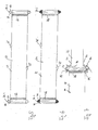
- Fig. 6 shows a further embodiment of a housing 72 in a heat exchanger block 71, which in turn has expansion elements 75 in the form of expansion beads.
- a bar in the form of a two-sided connecting bead 74.1, 74.2 is formed at the distal end, wherein the connecting bead 74.1, 74.2 has a sealing surface 78 and a clamping surface 79.
- the arrangement of the Ranwulstes 74.1, 74.2 with respect to the tube sheet 76 and the function of the clamping surface 79 and the sealing surface 78 corresponds to the function of the clamping surface 39 and the sealing surface 38, as based on Fig. 2A, Fig. 2B explained.
- Fig. 7 shows a further embodiment of a housing 82 with respect to a connecting line 33.
- a terminal block 99 in the form of a V-shaped connecting bead with a connection sealing surface 98 and a terminal clamping surface 97 is integrally formed on the connecting line 33.
- the housing 82 of the heat exchanger block 81 is provided at the distal end behind the tube sheet 86 with a funnel-shaped widening 84 and has a corresponding sealing surface 88 and clamping surface 89.
- a clamping element 90 engages the clamping surface 89 and the terminal clamping surface 97 and allows the sealing abutment of the sealing surface 88 and the connection sealing surface 98 by exerting a clamping force KK.
- the function of the connection is thus identical to that in FIG Fig. 2 explained function of the connection.
- the invention relates to a heat exchanger 10, in particular gas cooler, for heat exchange between a working fluid AF on the one hand, in particular an exhaust gas and / or a charge air, and a cooling fluid KF on the other hand, in particular a coolant, with a heat exchanger block for implementing the heat exchange.
- the heat exchanger block 11, 31, 41, 51, 61, 71, 81 for connection to a connecting line 33, 33.1, 33.2 has an end-side section arranged on the connection side with a strip, which has a sealing surface 38, 48, 58, 68, 78, 88 and a clamping surface has 39, 49, 59, 69, 79, 89, wherein the rake face 39, 49, 59, 69, 79, 89 as a contact surface for a clamping element 90, and the sealing surface 38, 48 , 58, 68, 78, 88 as a contact surface for the connecting line 33, 33.1, 33.2 is formed.
- the invention also leads to a heat exchanger system 100th
Landscapes
- Engineering & Computer Science (AREA)
- Physics & Mathematics (AREA)
- Thermal Sciences (AREA)
- Mechanical Engineering (AREA)
- General Engineering & Computer Science (AREA)
- Heat-Exchange Devices With Radiators And Conduit Assemblies (AREA)
Abstract
Description
- Die Erfindung betrifft einen Wärmetauscher, zum Wärmetausch zwischen einem Arbeitsfluid einerseits und einem Kühlfluid andererseits, mit einem Wärmetauscherkern zur Umsetzung des Wärmetausches. Die Erfindung betrifft auch ein Wärmetauschersystem.
- Wärmetauscher der eingangs genannten Art werden insbesondere als Gaskühler im Rahmen eines Aufladesystems für eine Brennkraftmaschine eingesetzt. Arbeitsfluid in Form von Gas kann als Abgas und/oder eine Ladeluft der Brennkraftmaschine, komprimiert und gekühlt, eingangsseitig der Brennkraftmaschine wieder zugeführt werden. Aufladesysteme, insbesondere Abgasruckführsysteme solcher Art, dienen neben einer Leistungssteigerung der Brennkraftmaschine auch der Schadstoffreduktion, insbesondere der Stickoxidreduktion, in den an die Umgebung abgegebenen Abgasen.
- Ein Wärmetauscherblock weist zur Umsetzung des Wärmetausches regelmäßig einen Kern zur voneinander getrennten und wärmetauschenden Führung des Arbeitsfluid und des Kühlfluids auf sowie ein den Kern aufnehmendes, von dem Kühlfluid durchströmbare Gehäuse auf. Zum Anschluss des Wärmetauscherblocks an eine Anschlussleitung ist es bislang üblich das Gehäuse desselben, mit einer Flanschplatte zu versehen. Eine solche Flanschplatte wird üblicherweise an das Gehäuse angeschweißt und ist regelmäßig aus einem hochwertigen Material, wie beispielsweise Edelstahl, gefertigt. Ein Anschlussflansch der Anschlussleitung dient zur Anbindung an die Flanschplatte, ggf. mit einem Dichtelement. Der Anschlussflansch wird regelmäßig an die Flanschplatte geschraubt.
- Diese Art der Anbindung eines Wärmetauscherblocks an die Anschlussleitung hat sich bewährt, ist gleichwohl vergleichsweise aufwendig. Zum einen ist der Schweißprozess aufwändig und kann thermische Spannungen im Material induzieren, sodass regelmäßig eine Dimensionskontrolle erforderlich ist. Zum anderen sind Anschlußteile der Anschlussleitung, wie beispielsweise ein Diffusor oder ein Stutzen der Anschlussleitung, separat zu fertigen. Dazu müssen entsprechende separate Werkzeuge zur Verfügung stehen. Die Montage der Anschlussleitung sowie etwaiger Anschlussteile der Anschlussleitung hat, wie erläutert, in einem separaten Prozessschritt zu erfolgen.
- Wünschenswert wäre, bei weiterhin qualitativ guter Anbindung von Wärmetauscher und Anschlussleitung, die Prozessschritte bei der Fertigung zu vereinfachen, insbesondere kostengünstiger zu realisieren.
- An dieser Stelle setzt die Erfindung an, deren Aufgabe es ist, einen Wärmetauscher anzugeben, welcher sich vergleichsweise einfach und dennoch verlässlich an eine Anschlussleitung anbinden lässt. Insbesondere soll ein Wärmetauscher einfacher und, soweit möglich, kostengünstiger aufgebaut bzw. herstellbar sein.
- Die Aufgabe wird durch die Erfindung mittels einem Wärmetauscher der eingangs genannten Art gelöst, bei dem erfindungsgemäß der Wärmetauscherblock zum Anschluss an eine Anschlussleitung einen an der Anschlussseite angeordneten endseitigen Abschnitt mit einer Leiste aufweist, welche eine Dichtfläche und eine Spannfläche aufweist, wobei die Spannfläche als Angriffsfläche für ein Spannelement und die Dichtfläche als Anlagefläche für die Anschlussleitung ausgebildet ist.
- Ein Wärmetauscher gemäß der Erfindung findet insbesondere Verwerdung als Abgaskühler zur Abgaskühlung in einem Abgasrückführsystem und/oder als Ladeluftkühler in einem Ladeluftzuführsystem, In beiden Fällen ist ein Wärmetauscher gemäß der Erfindung vorzugsweise als ein Gaskühler ausgebildet.
- Vorzugsweise weist der Wärmetauscherblock einen Kern zur voneinander getrennten und wärmetauschenden Führung des Arbeitsfluids und des Kühlfluids sowie ein den Kern aufnehmendes, von dem Kühlfluid durchströmbares Gehäuse auf. Gemäß dem Konzept der Erfindung ist das Gehäuse und/oder der Kern zum Anschluss an die Anschlussleitung ausgebildet. Mit anderen Worten weist das Gehäuse und/oder der Kern - z.B. ein Boden des Kerns - einen an der Anschlussseite angeordneten endseitigen Abschnitt mit einer Leiste auf, welche eine Dichtfläche und eine Spanfläche aufweist, wobei die Spannfläche als Angriffsfläche für ein Spannelement und die Dichtfläche als Anlagefläche für die Anschlussleitung ausgebildet ist.
- Insbesondere eignet sich ein die Strömungskanäle aufnehmender Boden des Kerns zur Anbringung der Leiste. Ein Boden ist mit einer Anzahl von Öffnungen versehen, in denen endseitige Abschnitte der Strömungskanäle aufgenommen sind. Eine Öffnung kann beispielsweise in Form eines Durchzugs für einen Strömungskanal gebildet sein.
- Die Erfindung geht von der Überlegung aus, dass die Anbindung einer Anschlussleitung über einen Flansch, wie es bisher im Stand der Technik üblich ist - insbesondere für bestimmte Belastungen in der Anschlussleitung - durch eine einfachere Lösung ersetzt werden kann. Die Erfindung hat erkannt, dass ein an der Anschlussseite angeordneter endseitiger Abschnitt mit einer Leiste, die eine Dichtfläche und eine Spannfläche aufweist, einfach zu realisieren ist und gleichwohl eine sichere Anbindung der Anschlussleitung erlaubt. Dies gilt insbesondere für eine, vorzugsweise V-förmige, Anordnung der Spannfläche und Dichtfläche. Dies ermöglicht es, einem gleichzeitig an der Spannfläche und einer Anschlussspannfläche der Anschlussleitung angreifenden Spannelement eine Anschlussdtchtfläche der Anschlussleitung auf die Dichtfläche der Leiste zu pressen. Dadurch wird die Anschlussleitung sicher und dennoch einfach an den Wärmetauscherblock angeschlossen.
- Dementsprechend führt das Konzept der Erfindung zur Lösung der Aufgabe auch auf ein Wärmetauschersystem mit einem vorgenannten Wärmetauscher und einer Anschlussleitung, wobei die Anschlussleitung einen an der Anschlussseite angeordneten endseitigen Anschnitt mit einer Anschlussleiste aufweist, welche eine Anschlussdichtfläche und eine Anschlussspannfläche aufweist. Erfindurigsgemäß ist dabei vorgesehen, dass die Anschlussspannfläche als Angriffsfläche für das Spannelement und die Anschlussdichtfläche als Anlagefläche für den Wärmetauscherblock ausgebildet ist.
- Das Spannelement kann beispielsweise als Schelle, Klemme oder sonstiges geeignetes Mittel zum dichtenden aneinanderhalten - also unter Spannung - des Wärmetauscherstocks und der Anschlussleitung ausgebildet sein. Dadurch wird ein Aneinanderpressen der Dichtfläche und der Anschlussdichtfläche über die Spannfläche und die Anschlussspannfläche ermöglicht. Die Dichtfläche des Wärmetauscherblocks und die Ansclussdichtfläche der Anschlussleitung können, soweit technisch realisierbar, ohne ein separates Dichtelement gasdicht aneinander gepresst werden. In dieser Ausführung eignet sich ein Wärmetauscher, insbesondere Gaskühler, vorzugsweise als ein Niederdruckwärmetauscher Ein Niederdruckwärmetauscher kann in einem Niederdruckbereich eines Aufladesystems verwendet werden. Insbesondere bei Einsatz eines Dichtelements zwischen der Dichtfläche und der Anschlussdichtfläche kann ein Wärmetauscher bzw ein Wärmelauschersystem gemäß dem Konzept der Erfindung auch in einem Hochdruckteil eines Aufladesystems eingesetzt werden.
- Unter einer Anschlussleitung kann, im vorliegenden Fall, jedes Anschlussteil verstanden werden, das im Rahmen eines Aufladesystems zum Anschluss an einen Wärmetauscher nützlich ist. Insbesondere kann eine Anschlussleitung in Form eines Anschlussstutzens gebildet sein, insbesondere in Form eines Anschlussstutzens mit Diffusor Ein Diffusor dient insbesondere dazu, eine gleichmäßige Anströmung der Strömungskanäle im Kern des Wärmetauscherblocks zu gewährleisten. Dies wird insbesondere relevant, wenn die Anschlussleitung im übrigen Bereich einen kleineren Querschnitt aufweist als die Anstromfläche der Anordnung der Strömungskanäle im Kern des Wärmetauscherblocks.
- Es hat sich mit Vorteil herausgestellt, dass, insbesondere in einer Niederdruckanwendung des Wärmetauschers, bereits Anschlussleitungen mit vergleichsweise großem Querschnitt eingesetzt werden, sodass ggf. ein Diffusor zum Anschluss an den Wärmetauscherblock entfallen kann. Somit kann das vorliegende Konzept der Erfindung vorteilhaft genutzt werden, um eine weiterführende Anschlussleitung eines Aufladesystems ohne Diffusor direkt an einen Wärmetauscherblock anzuschließen. Die Anschlussleitung kann eine Zuführleitung oder eine Abführleitung sein,
- Weitere vorteilhafte Weiterbildungen der Erfindung sind den Unteransprüchen zu entnehmen und geben im Einzelnen vorteilhafte Möglichkeiten an, das oben erläuterte Konzept im Rahmen der Aufgabenstellung sowie hinsichtlich weiterer Vorteile zu realisieren.
- Vorzugsweise ist die Leiste an einem an der Anschlußseite angeordneten endseitigen Abschnitt des Gehäuses angeordnet. Von der Weiterbildung wurde erkannt, dass das Gehäuse bereits einen vorteilhaft stabilen Aufbau und eine ausreichende Materialstärke hat, was sich zum Anschluss einer Anschlussleitung eignet. In Bezug auf einen Boden des Wärmetauscherkerns kann die Leiste in axialer Ausrichtung des Gehäuses vorteilhaft hinter einem Boden des Wärmetauscherkerns angeordnet sein. Insbesondere kann die Leiste an einem der Anschlussleiste zugewandten, distalen Ende des Gehäuses angeordnet sein. Anders ausgedrückt wird auf einer Eingangsseite des Wärmetauschers zunächst der Querschnitt der Anschlussleiste durchströmt, und anschließend tritt die Strömung des Arbeitsfluids in die im Boden gehaltenen Strömungskanäle ein. Somit wird eine vorteilhafte Strömungscharakteristik im Bereich der Anbindung der Anschlussleitung an den Wärmetauscher erreicht.
- Grundsätzlich kann in anderen Weiterbildungen, je nach Bedarf, die Leiste auch vor oder fluchtend zu einem Boden des Wärmetauscherkerns angeordnet sein.
- In besonders bevorzugter Weise ist die Leiste außenliegend am Wärmetauscherkern, insbesondere am Gehäuse, angeordnet. Durch die außenliegende Anordnung wird vermieden, dass ein Anströmquerschnitt der Strömungskanäle durch die Leiste unnötig verringert wird. Je nach Ausführung der Leiste kann diese auch eine Diffusorwirkung bei der Anströmung der Strömungskanäle unterstützen oder ausüben. Dieser Vorteil eignet sich insbesondere für eine Niederdruckanwendung des Wärmetauschers, um einen Diffusor als separates Bauteil entbehrlich zu machen.
- Die Ausführung einer Spannfläche und/oder Dichtfläche kann grundsätzlich je nach Bedarf erfolgen, soweit die Funktionalität eines Spannelements und eine Dichtigkeit der Anschlussstelle gewährleistet sind. Als besonders vorteilhaft hat sich erwiesen, dass die Spannfläche und/oder Dichtfläche schräg gegen eine Achse des Wärmetauscherblocks gestellt ist. In besonders vorteilhafter Weise sind die Spannfläche und die Dichtfläche gegeneinander gerichtet. Beispielsweise können die Spannfläche und die Dichtfläche etwa in der Form eines umgekehrten "V" gegeneinander gerichtet und außenliegend am Wärmetauscherblock angeordnet bzw. mit dem Block gebildet sein. Beispielsweise kann die Leiste einstückig oder integral mit dem Gehäuse oder einem Boden des Kerns ausgebildet werden. Hier hat sich insbesondere eine Leiste in Form einer Anschlusssicke als vorteilhaft erwiesen. Insbesondere eine nach außen gerichtete Anschlusssicke kann vergleichsweise einfach als Ausstülpung, beispielsweise des Gehäuses des Wärmetauscherblocks, hergestellt werden.
- In einer anderen Variante kann die Leiste in Form eines zweischenkligen Anschlussbords gebildet sein. Insbesondere ein nach außen gerichtetes Anschlussbord lässt sich leicht durch ein nach außen gerichtetes, zweimaliges Umbiegen des distalen Endes des Gehäuses erreichen. Das zweischenkliges Anschlussboard bildet dadurch einen in etwa V-förmigen Kragen am distalen Ende des Gehäuses oder Wärmetauscherkerns.
- In einer weiteren Variante kann die Leiste in Form eines zweiseitigen Anschlusswulstes gebildet sein. Ein solcher zweiseitiger Anschlusswulst ist vorteilhaft in Vollmaterialausfünrung außenseitig am Gehäuse oder Wärmetauscherkern angebracht. Dadurch wird dem Gehäuse bzw. dem Wärmetauscherkern aufgrund der höheren Materialansammlung zusätzlich Stabilität verliehen.
- In einer von den vorgenannten Weiterbildungen abweichenden Variante kann die Spannfläche und die Dichtfläche gleichgerichtet sein. Insbesondere ist dies der Fall, wenn die Spannfläche und die Dichtfläche zwei Seiten einer Wand, beispielsweise einer Gehäusewand, bilden. Die Leiste ist gemäß dieser Weiterbildung vorteihaft in Form einer trichterförmigen Ausweitung des Wärmetauscherkerns gebildet.
- Hinsichtlich des Wärmetauschersystems kann, im Rahmen einer besonders bevorzugten Weiterbildung einer Leiste, die Spannfläche und die Dichtfläche gegeneinander gerichtet sein und - anschlussgerecht - bei der Anschlussleiste die Anschlussspannfläche und die Anschlussdichtfläche gleichgerichtet sein. Mit anderen Worten wird eine auf der Innenseite einer trichterförmigen Aufweitung der Anschlussleitung liegende Anschlussdichtfläche auf eine außenliegende Dichtfläche gepresst und stellt so die Anbindung der Anschlussleistung zur Verfügung.
- In einer dazu alternativen Ausführungsform sind die Rollen beim Anschluss der Anschlussleitung und des Wärmetauschers vertauscht. Bei der Leiste des Wärmetauscherblocks ist die Spannfläche und die Dichtfläche gleichgerichtet, während bei der Anschlussleiste die Anschlussspannfläche und die Anschlussdichtfläche gegeneinander gerichtet sind.
- Um eine vergleichsweise dichte Anbindung der Anschlussleitung auch bei fehlender Dichtung zu gewährleisten, hat es sich als vorteilhaft erwiesen, dass eine Materialstärke der Anschlussleiste dünner als die der Leiste ist.
- Ausführungsbeispiele der Erfindung werden nun nachfolgend anhand der Zeichnung beschrieben. Diese soll die Ausführungsbeispiele nicht notwendigerweise maßstäblich darstellen, vielmehr ist die Zeichnung, wo zur Erläuterung dienlich, in schematisierter und/oder leicht verzerrter Form ausgeführt. Im Hinblick auf Ergänzungen der aus der Zeichnung unmittelbar erkennbaren Lehren wird auf den einschlägigen Stand der Technik verwiesen. Dabei ist zu berücksichtigen, dass vielfältige Modifikationen und Änderungen betreffend die Form und das Detail einer Ausführungsform vorgenommen werden können, ohne von der allgemeinen Idee der Erfindung abzuweichen. Die in der Beschreibung, in der Zeichnung sowie in den Ansprüchen offenbarten Merkmale der Erfindung können sowohl einzeln als auch in beliebiger Kombination für die Weiterbildung der Erfindung wesentlich sein. Zudem fallen in den Rahmen der Erfindung alle Kombinationen aus zumindest zwei der in der Beschreibung, der Zeichnung und/oder den Ansprüchen offenbarten Merkmale. Die allgemeine Idee der Erfindung ist nicht beschränkt auf die exakte Form oder das Detail der im folgenden gezeigten und beschriebenen bevorzugten Ausführungsform oder beschränkt auf einen Gegenstand, der eingeschränkt wäre im Vergleich zu dem in den Ansprüchen beanspruchten Gegenstand. Bei angegebenen Bemessungsbereichen sollen auch innerhalb der genannten Grenzen liegende Werte als Grenzwerte offenbart und beliebig einsetzbar und beanspruchbar sein. Der Einfachheit halber sind nachfolgend für identische oder ähnliche Teile oder Teile mit identischer oder ähnlicher Funktion gleiche Bezugszeichen verwendet.
- Weitere Vorteile, Merkmale und Einzelheiten der Erfindung ergeben sich aus der nachfolgenden Beschreibung der bevorzugten Ausführungsbeispiele sowie anhand der Zeichnung; diese zeigt in:
- Fig. 1:
- eine bevorzugte Ausführungsform eines Wärmetauschersystems mit einem Wärmetauscher und einer Leitung sowie den weiteren Ver- lauf der Leitung in einem vergrößerten Detail A;
- Fig. 2:
- in Ansicht (A) eine schematische Teilschnittdarstellung eines Ge- häuses eines Wärmetauschers gemäß einer bevorzugten Ausfüh- rungsform und in Ansicht (B) eine schematische Teilschnittdarstel- lung eines Wärmetauschersystems mit dem Wärmetauscher, einer Anschlussleitung und einem Spannelement gemäß einer weiteren ersten bevorzugten Ausführungsform;
- Fig. 3, Fig. 4:
- abgewandelte Anordnungen einer Leiste - hier in Form einer außen- liegenden, V-förmigen Anschlusssicke am distalen Ende eines Ge- häuses eines Wärmetauscherblocks - in Bezug auf einen Boden des Wärmetauscherkerns für eine weitere zweite und dritte Ausfüh- rungsform eines Wärmetauschers;
- Fig. 5. Fig. 6:
- Varianten einer Ausführung einer Leiste am distalen Ende eines Ge- häuses eines Wärmetauscherblocks für eine weitere vierte und fünf- te Ausführungsform eines Wärmetauschers und
- Fig. 7:
- eine zu
Fig. 2B umgekehrte Anbindung einer Anschlussleitung an ein Gehäuse für eine weitere sechste bevorzugte Ausführungsform eines Wärmetauschers. -
Fig. 1 zeigt ein Wärmetauschersystem 100 mit einem Wärmetauscher 10 und einer mehrteiligen Leitung 20. Der Wärmetauscher 10 weist einen Wärmetauscherblock 11 mit einem Gehäuse 12 sowie einem nicht näher dargestellten Wärmetauscherkern zur voneinander getrennten und wärmetauschenden Führung eines Arbeitsfluids AF und eines Kühlfluids KF auf. Das Arbeitsfluid AF wird über die Leitung 20 Strömungskanälen des Wärmetauscherkerns zugeführt, welche vom Kühlfluid KF in einer Kammer des Gehäuses 12 umströmt werden. - Die mehrteilige Leitung 20 weist einen Diffusor 21, ein Dehnungselement 22 in Form eines Faltenbalgs sowie einen Anschlussstutzen 23 auf, welcher im Detail A der
Fig. 1 vergrößert dargestellt ist. Das Dehnungselement 22 und der Anschtussstutzen 23 sind vorliegend über eine Klemmschelle 24 miteinander verbunden. Weitere Teile der Leitung 20, die Teil eines Abgasrückführungssystems sind, können über eine am Stutzen angebrachte Flanschplatte 25 angebunden werden. - Eine Flanschplatte wird im Stand der Technik auch verwendet, um eine direkte Anschlussleitung oder andere Teile der Leitung 20, wie beispielsweise einen Diffusor 21, am Wärmetauscher 10 anzubinden.
- Eine vereinfachte und insbesondere in der Herstellung leichter realisierbare Anbindung einer direkten Anschlussleitung an einen Wärmetauscher 10 ist im Rahmen der im Folgenden beschriebenen Ausführungsformen gemäß dem Konzept der Erfindung möglich.
- Dazu ist in
Fig. 2 eine erste Ausführungsform anhand eines schematisch dargestellten Gehäuses 32 eines Wäanetauscherblocks 31 gezeigt. Das schematisch dargestellte Gehäuse 32 derFig. 2 sowie die weiteren im Rahmen derFig. 3 bis Fig. 7 erläuterten Gehäuse 42, 52, 62, 72 und 82 als Teil der weiter erläuterten Wärmelauscherblöcke 41, 51, 61, 71 und 81 können bei dem inFig. 1 erläuterten Wärmetauschersystem 100 bzw. Wärmetauscher 10 anstatt des dort gezeigten Gehäuses 12 bzw. Wärmetauscherblocks 11 eingesetzt werden. - Der Wärmetauscherblock 31 der
Fig. 2A weist zum Anschluss an eine inFig. 2B dargestellte Anschlussleitung 33.1, 33.2 einen an der Anschlußseite I, II angeordneten endseitigen Abschnitt mit einer Leiste auf, die bei der Ausführungsform derFig. 2 in Form einer nach außen gerichteten V-förmigen Anschlusssicke 34.1, 34.2 gebildet ist. Vorliegend ist sowohl eine eingangsseitige Anschlusssicke 34.1 zum Anschluss einer zuführenden Anschlussleitung 33.1 als auch eine ausgangsseitige Anschlusssicke 34.2 zum Anschluss einer abführenden Anschlussleitung 33.2 vorgesehen. Weiter ist das Gehäuse 32 in einem Bereich des Wärmetauscherkerns mit nach außen gerichteten Dehnungssicken 35 versehen, von denen vorliegend zwei beispielhaft dargetellt sind. Der nicht im Einzelnen gezeichnete Wärmetauscherkern weist eine Reihe von Strömungskanälen auf, die in einem eingangsseitigen Rohrboden 36.1 und einem ausgangsseitigen Rohrboden 36.2 gehalten sind. Ein Rohrboden 36.1, 36.2 weist dazu eine der Anzahl von Strömungskanälen entsprechende Anzahl von Öffnungen 37 auf, die vorliegend als Durchzug, ggf. mit Kragen zur verbesserten Haltung der Strömungskanäle, im Rohrboden 36.1, 36.2 ausgebildet sind. Eine Anschlusssicke 34.1, 24.2 ist gemäß der inFig. 2 dargestellten Ausführungsform hinter einem Rohrboden 36.1, 36.2 eines Wärmetauscherkerns angeordnet, d.h. mit anderen Worten, der endseitige Abschnitt I, II ist vorliegend außerhalb des Bereichs des Wärmetauscherkerns angeordnet. - Eine Anschlusssicke 34.1, 34.2 weist zur Ausübung ihrer Anschlussfunktion eine Dichtfläche 38 und eine Spannfläche 39 auf, die schräg gegen eine Achse A des Gehäuses 32 und zur Bildung einer V-Form schräg gegeneinander gerichtet sind. Eine Anschlusssicke 34.1, 34 2 bildet mit ihrer Dichtfläche 38 ein distales Ende des Gehäuses 32 und fluchtet mit der auslaufenden Spannfläche 39 im Wesentlichen mit einem Rohrboden 36.1, 36.2.
- Es hat sich gezeigt, dass durch diese Anordnung einer Anschlusssicke 34.1, 34.2 hinsichtlich ihrer axialen Position zu einem Rohrboden 36.1, 36.2 eine besonders vorteilhafte Einströmcharakteristik des Arbeitsfluids AF von einer Anschlussleitung 33.1, 33.2 in das Gehäuse 32 erreichbar ist.
- Wie aus
Fig. 2B ersichtlich ist, lässt sich eine Zuführleitung 33.1 bzw. Abführleitung 33.2 mit einer trichterförmigen Aufweitung 91 versehen. Vorwiegend ist die Aufweitung 91 aus dünnerem Material gebildet als die Leiste des Gehäuses 32. Eine innenliegende Anschlussdichtfläche 92 der Aufweitung 91 lässt sich somit eng an die Dichtfläche 38 der Anschlusssicke 34.1, 34.2 anbringen und anschmiegen. Um die dichtende Wirkung zu erhöhen, kann ggfs - in einer hier nicht gezeigten Ausführungsform - zwischen der Dichtfläche 38 und der Anschlussdichtfläche 92 ein Dichtelement vorgesehen sein. Insbesondere für Niederdruckanwendungen eignet sich jedoch auch die Ausführung der Aufweitung 91 mit einer Materialstärke geringer als eine Materialstärke der Anschlusssicke 34.1, 34.2. Auf diese Weise wird eine vergleichsweise gute Materialanformung der trichterförmigen Aufweitung an die Anschlusssicke 34.1, 34.2 im Bereich der Anschlussdichtfläche 92 bzw. der Dichtfläche 38 erreicht. - Ein an der Anschlussspannfläche 93 der trichterförmigen Aufweitung 91 angreifendes Spannelement 90 übt eine Klemmkraft KK auf die Spannfläche 39 und die Anschlussspannfläche 93 aus, sodass die Anschlussleitung 33.1, 33.2 dichtend an das Gehäuse 32 angeschlossen wird.
-
Fig. 3 und Fig. 4 zeigen Variationen des Gehäuses 32 hinsichtlich der axialen Positionierung einer Anschlusssicke 34.1, 34.2 in Bezug auf einen Rohrboden 36.1, 36.2.Fig. 3 zeigt dazu ein Gehäuse 42 eines teilweise dargestellten Wärmetauscherblocks 41, bei welchem eine wie inFig. 2 erläutert ausgebildete und funktionierende Anschlusssicke 44 am distalen Ende des Gehäuses 42 so angeordnet ist, dass diese mit ihrem Zenit 47 zwischen Spannfläche 49 und Dichtfläche 48 im Wesentlichen mit einem Rohrboden 46 des Wärmetauscherkerns fluchtet. -
Fig. 4 zeigt ein Gehäuse 52 eines Wärmetauscherblocks 51, bei dem die Anschlusssicke 54 am distalen Ende des Gehäuses 52 so angeordnet ist, dass diese am distalen Ende mit ihrer Dichtfläche 58 mit dem Rohrboden 56 des Warmetauscherkerns fluchtet. Der Bereich des Zenits 57 und der Spannfläche 59 der Anschlusssicke 54 überlappt somit mit einem Rohrboden und einem unmittelbar daran anschließenden endseitigen Strömungskanalabschnitt des Wärmetauscherkerns. Anders ausgedrückt überlappt ein endseitiger Abschnitt I, II bei der Ausführungsform derFig. 3 hälftig und bei der Ausführungsform derFig. 4 vollständig mit einem endseitigen Bereich des Warmetauscherkerns. -
Fig. 5 zeigt eine weitere Ausführungsform eines Gehäuses 62 bei einem Wärmetauscherblock 61, wobei das Gehäuse 62 wiederum mit Dehnungssicken 65 im Bereich des Wärmetauscherkerns versehen ist. Eine in Form eines zweischenkligen Anschlussbords 64.1, 64.2 gebildete Leiste ist vorliegend nach außen gerichtet und übt eine Funktion aus, wie diese anhand der Anschlusssicke 34.1, 34.2 inFig. 2A und Fig. 2B erläutert wurde. Die axiale Anordnung des zweischenkeligen Anschlussbords 64.1, 64.2 in Bezug auf einen Rohrboden 66 entspricht dabei der Anordnung einer Anschlusssicke 34.1, 34.2 derFig. 2A, Fig. 2B , d.h. das zweischenkelige Anschlussbord 64.1, 64.2 bildet das distale Ende des Gehäuses 62 und fluchtet mit seiner Spannfläche 69 mit dem Rohrboden 66, Eine Dichtfläche 68 fluchtet mit dem distalen Ende. Die Dichtfläche 68 ergibt sich durch einmaliges Aufbiegen des Gehäuserandes. Die Spannfläche 69 ergibt sich durch zweimaliges Umbiegen des Gehäuserandes nach außen, Insgesamt entsteht das nach außen gerichtete Anschlussbord durch zweimaliges Umbiegen des Gehäuserandes nach außen. -
Fig. 6 zeigt eine weitere Ausführungsform eines Gehäuses 72 bei einem Wärmetauscherblock 71, welches wiederum Dehnungselemente 75 in Form von Dehnungssicken aufweist. Bei der inFig 6 gezeigten Ausführungsform ist am distalen Ende eine Leiste in Form eines zweiseitigen Anschlusswulstes 74.1, 74.2 gebildet, wobei der Anschlusswulst 74.1, 74.2 eine Dichtfläche 78 und eine Spannfläche 79 aufweist. Die Anordnung des Anschlusswulstes 74.1, 74.2 in Bezug auf den Rohrboden 76 als auch die Funktion der Spannfläche 79 und der Dichtfläche 78 entspricht der Funktion der Spannfläche 39 und der Dichtfläche 38, wie anhand vonFig. 2A, Fig. 2B erläutert. -
Fig. 7 zeigt eine weitere Ausführungsform eines Gehäuses 82 in Bezug auf eine Anschlussleitung 33. Dabei sind die Elemente der Anbindung bezüglich des Gehäuses 82 und der Anschlussleitung 33 in Vergleich zuFig. 2B vertauscht. Mit anderen Worten ist an der Anschlussleitung 33 eine Anschlussleiste 99 in Form einer V-förmigen Anschlusssicke mit einer Anschlussdichtfläche 98 und einer Anschlussspannfläche 97 angeformt. Das Gehäuse 82 des Wärmetauscherblocks 81 ist am distalen Ende hinter dem Rohrboden 86 mit einer trichterförmigen Aufweitung 84 versehen und weist eine entsprechende Dichtfläche 88 und Spannfläche 89 auf. Wiederum greift vorliegend ein Spannelement 90 an die Spannfläche 89 und die Anschlussspannfläche 97 an und ermöglicht durch Ausübung einer Klemmkraft KK das dichtende Aneinanderliegen der Dichtfläche 88 und der Anschlussdichtfläche 98. Die Funktion der Anbindung ist somit identisch zu der inFig. 2 erläuterten Funktion der Anbindung. - Zusammenfassend betrifft die Erfindung einen Wärmetauscher 10, insbesondere Gaskühler, zum Wärmetausch zwischen einem Arbeitsfluid AF einerseits, insbesondere einem Abgas und/oder einer Ladeluft, und einem Kühlfluid KF andererseits, insbesondere einem Kühlmittel, mit einem Wärmetauscherblock zur Umsetzung des Wärmetausches. Erfindungsgemäß ist dabei vorgesehen, dass der Wärmetauscherblock 11, 31, 41, 51, 61, 71, 81 zum Anschluss an eine Anschlussleitung 33, 33.1, 33.2 einen an der Anschlussseite angeordneten endseitigen Abschnitt mit einer Leiste aufweist, welche eine Dichtfläche 38, 48, 58, 68, 78, 88 und eine Spannfläche aufweist 39, 49, 59, 69, 79, 89, wobei die Spanfläche 39, 49, 59, 69, 79, 89 als Angriffsfläche für ein Spannelement 90, und die Dichtfläche 38, 48, 58, 68, 78, 88 als Anlagefläche für die Anschlussleitung 33, 33.1, 33.2 ausgebildet ist Die Erfindung führt auch auf ein Wärmetauschersystem 100.
-
- 10
- Wärmetauscher
- 11
- Wärmetauscherblock
- 12
- Gehäuse
- 20
- Leitung
- 21
- Diffusor
- 22
- Dehnungselement
- 23
- Anschlussstutzen
- 24
- Klemmschelle
- 25
- Flanschplatte
- 31
- Wärmetauscherblock
- 32
- Gehäuse
- 33
- Anschlussleitung
- 33.1
- Anschlussleitung, Zuführleitung
- 33.2
- Anschlussleitung, Abführfeitung
- 34.1
- eingangsseitige Anschlusssicke
- 34.2
- ausgangsseitige Anschlusssicke
- 35
- Dehnungssicken
- 36.1
- eingangsseitiger Rohrboden
- 36.2
- ausgangsseitiger Rohrboden
- 37
- Öffnungen
- 38
- Dichtfläche
- 39
- Spannfläche
- 41
- Wärmetauscherblock
- 42
- Gehäuse
- 44
- Anschlusssicke
- 46
- Rohrboden
- 47
- Zenit
- 48
- Dichtfläche
- 49
- Spannfläche
- 51
- Wärmetauscherblock
- 52
- Wärmetauschergehäuse, Gehäuse
- 54
- Anschlusssicke
- 56
- Rohrboden
- 57
- Zenit
- 58
- Dichtfläche
- 59
- Spannfläche
- 61
- Wärmetauscherblock
- 62
- Gehäuse
- 64.1
- Anschlussbord
- 64.2
- Anschlussbord
- 65
- Dehnungssicken
- 66
- Rohrboden
- 68
- Dichtfläche
- 69
- Spannfläche
- 71
- Wärmetauscherblock
- 72
- Gehäuse
- 74.1
- Anschlusswulst
- 74.2
- Anschlusswulst
- 75
- Dehnungselemente
- 76
- Rohrboden
- 78
- Dichtfläche
- 79
- Spannfläche
- 81
- Wärmetauscherblock
- 82
- Gehäuse
- 84
- trichterförmige Aufweitung
- 86
- Rohrboden
- 88
- Dichtfläche
- 89
- Spannfläche
- 90
- Spannelement
- 91
- trichterförmige Aufweitung
- 92
- Anschlussdichtfläche
- 93
- Anschlussspannfläche
- 97
- Anschlussspannfläche
- 98
- Anschlussdichtfläche
- 99
- Anschlussleiste
- 100
- Wärmetauschersystem
- A
- Achse
- AF
- Arbeitsfluid
- KF
- Kühlfluid
- KK
- Klemmkraft
Claims (15)
- Wärmetauscher (10), insbesondere Gaskühler, zum Wärmetausch zwischen einem Arbeitsfluid (AF) einerseits, insbesondere einem Abgas und/oder einer Ladeluft, und einem Kühlfluid (KF) andererseits, insbesondere einem Kühlmittel, mit einem Wärmetauscherblock zur Umsetzung des Wärmetausches, dadurch gekennzeichnet, dass der Wärmetauscherblock (11, 31, 41, 51, 61, 71, 81) zum Anschluss an eine Anschlussleitung (33, 33.1, 33.2) einen an der Anschlussseite angeordneten endseitigen Abschnitt mit einer Leiste aufweist, welche eine Dichtfläche (38, 48, 58, 68, 78, 88) und eine Spannfläche aufweist (39, 49, 59, 69, 79, 89), wobei die Spannfläche (39, 49, 59, 69, 79, 89) als Angriffsfläche für ein Spannelement (90), und die Dichtfläche (38, 48, 58, 68, 78, 88) als Anlagefläche für die Anschlussleitung (33, 33.1, 33.2) ausgebildet ist.
- Wärmetauscher (10) nach Anspruch 1, dadurch gekennzeichnet, dass der Wärmetauscherblock (11, 31, 41, 51, 61, 71, 81) aufweist.- einen Wärmetauscherkern zur voneinander getrennten und wärmetauschenden Führung des Arbeitsfluids (AF) und des Kühlfluids (KF);- ein den Wärmetauscherkern aufnehmendes, von dem Kühlfluid (KF) durchströmbares Gehäuse (12, 32, 42, 52, 62, 72, 82); wobei das Gehäuse (12, 32, 42, 52, 62, 72, 82) und/oder der Wärmetauscherkern zum Anschluss an die Anschlussleitung (33, 33.1, 33.2) ausgebildet ist.
- Wärmetauscher (10) nach Anspruch 1 oder 2, dadurch gekennzeichnet, dass die Leiste an einem an der Anschlussseite angeordneten endseitigen Abschnitt des Gehäuses (12, 32, 42, 52, 62, 72, 82) angeordnet ist, insbesondere die Leiste vor, hinter oder fluchtend zu einem Boden (37, 47, 57, 67, 77, 87) des Wärmetauscherkerns angeordnet ist.
- Wärmetauscher (10) nach einem der Ansprüche 1 bis 3, dadurch gekennzeichnet, dass die Leiste außenliegend und/oder an einem der Anschlussseite zugewandten distalen Ende des Gehäuses (12, 32, 42, 52, 62, 72, 82) angeordnet ist.
- Wärmetauscher (10) nach einem der Ansprüche 1 bis 4, dadurch gekennzeichnet, dass die Spannfläche (39, 49, 59, 69, 79, 89) und/oder die Dichtfläche (38, 48, 58, 68, 78, 88) schräg gegen eine Achse (A), insbesondere Durchströmungsrichtung, des Warmetauscherblocks (11, 31, 41, 51, 61, 71, 81) gestellt ist.
- Wärmetauscher (10) nach einem der Ansprüche 1 bis 5, dadurch gekennzeichnet, dass die Spannfläche (39, 49, 59, 69, 79, 89) und die Dichtfläche (38, 48, 58, 68, 78, 88) gegeneinander gerichtet sind.
- Wärmetauscher (10) nach einem der Ansprüche 1 bis 6, dadurch gekennzeichnet, dass die Leiste in Form einer, vorzugsweise V-förmigen, Anschlusssicke (34.1, 34.2, 44, 54), insbesondere einer nach außen gerichteten Anschlusssicke, gebildet ist.
- Wärmetauscher (10) nach einem der Ansprüche 1 bis 7, dadurch gekennzeichnet, dass die Leiste in Form eines, vorzugsweise V-förmigen, zweischenkeligen Anschlussbords (64.1, 64.2), insbesondere nach außen gerichteten Anschlussbords, gebildet ist.
- Wärmetauscher (10) nach einem der Ansprüche 1 bis 8, dadurch gekennzeichnet, dass die Leiste in Form eines, vorzugsweise V-förmigen, zweiseitigen Anschlusswulstes (74.1, 74.2), insbesondere nach außen gerichteten Anschlusswulstes, gebildet ist.
- Wärmetauscher (10) nach einem der Ansprüche 1 bis 9, dadurch gekennzeichnet, dass die Spannfläche (39, 49, 59, 69, 79, 89) und die Dichtfläche (38, 48, 58, 68, 78, 88) gleichgerichtet sind.
- Wärmetauscher (10) nach einem der Ansprüche 1 bis 10, dadurch gekennzeichnet, dass die Leiste in Form einer trichterförmigen Aufweitung (84) des Wärmetauscherblocks gebildet ist.
- Wärmetauschersystem (100) mit einem Wärmetauscher (10) nach einem der Ansprüche 1 bis 11 und einer Anschlussleitung (33, 33.1, 33.2), wobei die Anschlussleitung (33, 33.1, 33.2) einen an der Anschlussseite angeordneten endseitigen Abschnitt mit einer Anschlussleiste (99) aufweist, welche eine Anschlussdichtfläche (92, 98) und eine Anschlussspannfläche (93, 97) aufweist, wobei die Anschlussspannfläche (93, 97) als Angriffsfläche für ein Spannelement (90), und die Anschlussdichtfläche (92, 98) als Anlagefläche für den Wärmetauscherblock (11, 31, 41, 51, 61, 71, 81) ausgebildet ist.
- Wärmetauschersystem (100) nach Anspruch 12, dadurch gekennzeichnet, dass bei der Anschlussleiste die Anschlussspannfläche (93) und die Anschlussdichtfläche (92) gleichgerichtet und bei der Leiste des Wärmetauschers (10) die Spannfläche (39, 49, 59, 69, 79, 89) und die Dichtfläche (38, 48, 58, 68, 78, 88) gegeneinander gerichtet sind.
- Wärmetauschersystem (100) nach Anspruch 12 oder 13, dadurch gekennzeichnet, dass bei der Anschlussleiste (99) die Anschlussspannfläche (97) und die Anschlussdichtfläche (98) gegeneinander gerichtet und bei der Leiste des Wärmetauschers (10) die Spannfläche (39, 49, 59, 69, 79, 89) und die Dichtfläche (38, 48, 58, 68, 78, 88) gleichgerichtet sind.
- Wärmetauschersystem (100) nach einem der Ansprüche 12 bis 14, dadurch gekennzeichnet, dass eine Materialstärke der Anschlussleiste dünner als die der Leiste ist.
Applications Claiming Priority (1)
| Application Number | Priority Date | Filing Date | Title |
|---|---|---|---|
| DE102009035674A DE102009035674A1 (de) | 2009-07-30 | 2009-07-30 | Wärmetauscher, Wärmetauschersystem |
Publications (4)
| Publication Number | Publication Date |
|---|---|
| EP2295921A2 true EP2295921A2 (de) | 2011-03-16 |
| EP2295921A3 EP2295921A3 (de) | 2015-02-25 |
| EP2295921B1 EP2295921B1 (de) | 2019-01-16 |
| EP2295921B2 EP2295921B2 (de) | 2022-01-19 |
Family
ID=43037678
Family Applications (1)
| Application Number | Title | Priority Date | Filing Date |
|---|---|---|---|
| EP10170777.6A Active EP2295921B2 (de) | 2009-07-30 | 2010-07-26 | Wärmetauscher mit Dichtfläche und Spannfläche aufweisenden Anschlussabschnitt |
Country Status (2)
| Country | Link |
|---|---|
| EP (1) | EP2295921B2 (de) |
| DE (1) | DE102009035674A1 (de) |
Families Citing this family (2)
| Publication number | Priority date | Publication date | Assignee | Title |
|---|---|---|---|---|
| DE102010025031A1 (de) * | 2010-06-24 | 2011-12-29 | Benteler Automobiltechnik Gmbh | Wärmetauscher |
| DE102012211311A1 (de) * | 2012-06-29 | 2014-01-02 | Behr Gmbh & Co. Kg | Abgaswärmeübertrager |
Family Cites Families (17)
| Publication number | Priority date | Publication date | Assignee | Title |
|---|---|---|---|---|
| DE3435093A1 (de) | 1984-09-25 | 1986-04-03 | Süddeutsche Kühlerfabrik Julius Fr. Behr GmbH & Co KG, 7000 Stuttgart | Waermetauscher mit einem in einem gehaeuse angeordneten rohrbuendel |
| US4993485A (en) | 1989-09-18 | 1991-02-19 | Gorman Jeremy W | Easily disassembled heat exchanger of high efficiency |
| DE9315921U1 (de) * | 1993-10-19 | 1995-02-16 | Gustav Wahler Gmbh U. Co, 73730 Esslingen | Einrichtung zur Abgasrückführung |
| DE9416421U1 (de) * | 1994-10-12 | 1995-07-27 | Gustav Wahler Gmbh U. Co, 73730 Esslingen | Leitungsverbindung einer Einrichtung zur Abgasrückführung |
| DE19631574C1 (de) * | 1996-07-26 | 1997-11-13 | Mannesmann Ag | Rohrverbindung |
| DE59810513D1 (de) * | 1997-01-29 | 2004-02-05 | Contitech Schlauch Gmbh | Schlauchanschluss für Ladeluftkühler |
| DE19717751C2 (de) * | 1997-04-21 | 2000-04-06 | Combas Rohrsanierungs Vertrieb | Muffenaußendichtung für Glockenmuffen |
| DE19833302A1 (de) * | 1998-07-24 | 2000-01-27 | Wahler Gmbh & Co Gustav | Leitungsverbindung bei einer Einrichtung zur Abgasrückführung |
| US20030070793A1 (en) * | 2001-10-15 | 2003-04-17 | Dierbeck Robert F. | Heat exchanger assembly with dissimilar metal connection capability |
| FR2833065B1 (fr) | 2001-12-05 | 2004-09-03 | Caillau Ets | Systeme de serrage pour le raccordement etanche de deux tubes ayant des surfaces d'appui |
| ES2209618B1 (es) * | 2002-05-28 | 2005-08-16 | Estampaciones Noroeste, S.A. | Intercambiador de calor para un sistema "egr" con un conducto de derivacion integrado. |
| DE10303910A1 (de) * | 2003-01-31 | 2004-08-12 | Arvin Technologies Inc., Columbus | Baugruppe bestehend aus Abgas-Wärmetauscher und Bypass |
| FR2856747B1 (fr) * | 2003-06-25 | 2005-09-23 | Valeo Thermique Moteur Sa | Module de refroidissement de l'air de suralimentation et des gaz d'echappement recircules d'un moteur a combustion interne de vehicule automobile. |
| US7213639B2 (en) * | 2005-03-16 | 2007-05-08 | Detroit Diesel Coporation | Heat exchanger exhaust gas recirculation cooler |
| DE102007031419A1 (de) * | 2006-07-06 | 2008-01-10 | Behr Gmbh & Co. Kg | Abgaskühler, insbesondere für ein Kraftfahrzeug |
| DE102007062826A1 (de) * | 2007-01-17 | 2008-09-25 | Behr Gmbh & Co. Kg | Wärmetauscher für ein Kraftfahrzeug |
| DE102007010474A1 (de) * | 2007-01-23 | 2008-07-24 | Behr Gmbh & Co. Kg | Wärmetauscher |
-
2009
- 2009-07-30 DE DE102009035674A patent/DE102009035674A1/de not_active Withdrawn
-
2010
- 2010-07-26 EP EP10170777.6A patent/EP2295921B2/de active Active
Also Published As
| Publication number | Publication date |
|---|---|
| DE102009035674A1 (de) | 2011-02-03 |
| EP2295921B1 (de) | 2019-01-16 |
| EP2295921A3 (de) | 2015-02-25 |
| EP2295921B2 (de) | 2022-01-19 |
Similar Documents
| Publication | Publication Date | Title |
|---|---|---|
| EP1979699B1 (de) | Rohrbündel-wärmetauscher | |
| EP2129988B1 (de) | Wärmetauscher, abgasrückführsystem, ladeluftzuführsystem und verwendung des wärmetauschers | |
| EP2667007B1 (de) | Wärmetauscher, Abgasrückführsystem und Brennkraftmaschine | |
| EP2066992A2 (de) | Wärmetauscher für einen verbrennungsmotor | |
| EP1204816A1 (de) | Mischelement für ein in einem rohr geführtes fluid | |
| EP2705319B1 (de) | Wärmetauscher, insbesondere ladeluftkühler | |
| EP3108194B1 (de) | Abgaswärmeübertrager | |
| EP1816425A2 (de) | Abgaswärmetauscher in einer Abgasrückführungsanordnung | |
| WO2007062939A1 (de) | Kühlvorrichtung für eine verbrennungskraftmaschine | |
| EP1518043A2 (de) | Abgasw rme bertrager und verfahren zu seiner herstellun g | |
| EP1690056B1 (de) | Wärmeübertrager, insbesondere für kraftfahrzeuge | |
| EP2037201A2 (de) | Ladeluftmodul für eine Verbrennungskraftmaschine | |
| DE2413165C3 (de) | Plattengegenstrom-Wärmeaustauscher und Verfahren zu seiner Herstellung | |
| EP2295921B1 (de) | Wärmetauscher mit Dichtfläche und Spannfläche aufweisenden Anschlussabschnitt | |
| EP1454109B1 (de) | Abgaswärmeübertrager | |
| EP3232149B1 (de) | Wärmeübertrager | |
| WO2007028465A1 (de) | Wärmetauscher | |
| EP3070426B1 (de) | Abgaswärmeübertrager | |
| EP2915989B1 (de) | Ladeluftkühler für eine Brennkraftmaschine | |
| DE10228485B4 (de) | Rohranordnung | |
| DE102004051680C5 (de) | Anordnung zur Befestigung eines Abgaskrümmers | |
| DE102021131552B3 (de) | Verfahren zur Herstellung eines Flachrohrs | |
| DE102022101656B4 (de) | Abgasrückführkühler, insbesondere für ein Kraftfahrzeug, sowie Kraftfahrzeug | |
| DE102017208210A1 (de) | Wärmetauscher | |
| EP2192288A2 (de) | Auflademodul, Aufladesystem und Brennkraftmaschine |
Legal Events
| Date | Code | Title | Description |
|---|---|---|---|
| PUAI | Public reference made under article 153(3) epc to a published international application that has entered the european phase |
Free format text: ORIGINAL CODE: 0009012 |
|
| AK | Designated contracting states |
Kind code of ref document: A2 Designated state(s): AL AT BE BG CH CY CZ DE DK EE ES FI FR GB GR HR HU IE IS IT LI LT LU LV MC MK MT NL NO PL PT RO SE SI SK SM TR |
|
| AX | Request for extension of the european patent |
Extension state: BA ME RS |
|
| PUAL | Search report despatched |
Free format text: ORIGINAL CODE: 0009013 |
|
| AK | Designated contracting states |
Kind code of ref document: A3 Designated state(s): AL AT BE BG CH CY CZ DE DK EE ES FI FR GB GR HR HU IE IS IT LI LT LU LV MC MK MT NL NO PL PT RO SE SI SK SM TR |
|
| AX | Request for extension of the european patent |
Extension state: BA ME RS |
|
| RIC1 | Information provided on ipc code assigned before grant |
Ipc: F02B 29/04 20060101ALI20150116BHEP Ipc: F16L 23/04 20060101ALI20150116BHEP Ipc: F02M 25/07 20060101ALI20150116BHEP Ipc: F28F 9/02 20060101AFI20150116BHEP |
|
| RAP1 | Party data changed (applicant data changed or rights of an application transferred) |
Owner name: MAHLE BEHR GMBH & CO. KG |
|
| 17P | Request for examination filed |
Effective date: 20150825 |
|
| RBV | Designated contracting states (corrected) |
Designated state(s): AL AT BE BG CH CY CZ DE DK EE ES FI FR GB GR HR HU IE IS IT LI LT LU LV MC MK MT NL NO PL PT RO SE SI SK SM TR |
|
| STAA | Information on the status of an ep patent application or granted ep patent |
Free format text: STATUS: EXAMINATION IS IN PROGRESS |
|
| 17Q | First examination report despatched |
Effective date: 20171120 |
|
| RIC1 | Information provided on ipc code assigned before grant |
Ipc: F28F 9/02 20060101AFI20180614BHEP Ipc: F16L 23/04 20060101ALI20180614BHEP Ipc: F02B 29/04 20060101ALI20180614BHEP |
|
| GRAP | Despatch of communication of intention to grant a patent |
Free format text: ORIGINAL CODE: EPIDOSNIGR1 |
|
| STAA | Information on the status of an ep patent application or granted ep patent |
Free format text: STATUS: GRANT OF PATENT IS INTENDED |
|
| INTG | Intention to grant announced |
Effective date: 20180808 |
|
| GRAJ | Information related to disapproval of communication of intention to grant by the applicant or resumption of examination proceedings by the epo deleted |
Free format text: ORIGINAL CODE: EPIDOSDIGR1 |
|
| STAA | Information on the status of an ep patent application or granted ep patent |
Free format text: STATUS: EXAMINATION IS IN PROGRESS |
|
| REG | Reference to a national code |
Ref country code: DE Ref legal event code: R079 Ref document number: 502010015733 Country of ref document: DE Free format text: PREVIOUS MAIN CLASS: F28F0009020000 Ipc: F28D0021000000 |
|
| GRAR | Information related to intention to grant a patent recorded |
Free format text: ORIGINAL CODE: EPIDOSNIGR71 |
|
| GRAS | Grant fee paid |
Free format text: ORIGINAL CODE: EPIDOSNIGR3 |
|
| STAA | Information on the status of an ep patent application or granted ep patent |
Free format text: STATUS: GRANT OF PATENT IS INTENDED |
|
| INTC | Intention to grant announced (deleted) | ||
| RIN1 | Information on inventor provided before grant (corrected) |
Inventor name: HERBER, ACHIM |
|
| GRAA | (expected) grant |
Free format text: ORIGINAL CODE: 0009210 |
|
| STAA | Information on the status of an ep patent application or granted ep patent |
Free format text: STATUS: THE PATENT HAS BEEN GRANTED |
|
| RIC1 | Information provided on ipc code assigned before grant |
Ipc: F02B 29/04 20060101ALI20181119BHEP Ipc: F28D 21/00 20060101AFI20181119BHEP Ipc: F16L 23/04 20060101ALI20181119BHEP Ipc: F28F 9/02 20060101ALI20181119BHEP |
|
| AK | Designated contracting states |
Kind code of ref document: B1 Designated state(s): AL AT BE BG CH CY CZ DE DK EE ES FI FR GB GR HR HU IE IS IT LI LT LU LV MC MK MT NL NO PL PT RO SE SI SK SM TR |
|
| INTG | Intention to grant announced |
Effective date: 20181211 |
|
| REG | Reference to a national code |
Ref country code: GB Ref legal event code: FG4D Free format text: NOT ENGLISH |
|
| REG | Reference to a national code |
Ref country code: CH Ref legal event code: EP |
|
| REG | Reference to a national code |
Ref country code: IE Ref legal event code: FG4D Free format text: LANGUAGE OF EP DOCUMENT: GERMAN |
|
| REG | Reference to a national code |
Ref country code: DE Ref legal event code: R096 Ref document number: 502010015733 Country of ref document: DE |
|
| REG | Reference to a national code |
Ref country code: AT Ref legal event code: REF Ref document number: 1090000 Country of ref document: AT Kind code of ref document: T Effective date: 20190215 |
|
| REG | Reference to a national code |
Ref country code: NL Ref legal event code: MP Effective date: 20190116 |
|
| REG | Reference to a national code |
Ref country code: LT Ref legal event code: MG4D |
|
| PG25 | Lapsed in a contracting state [announced via postgrant information from national office to epo] |
Ref country code: NL Free format text: LAPSE BECAUSE OF FAILURE TO SUBMIT A TRANSLATION OF THE DESCRIPTION OR TO PAY THE FEE WITHIN THE PRESCRIBED TIME-LIMIT Effective date: 20190116 |
|
| PG25 | Lapsed in a contracting state [announced via postgrant information from national office to epo] |
Ref country code: NO Free format text: LAPSE BECAUSE OF FAILURE TO SUBMIT A TRANSLATION OF THE DESCRIPTION OR TO PAY THE FEE WITHIN THE PRESCRIBED TIME-LIMIT Effective date: 20190416 Ref country code: PL Free format text: LAPSE BECAUSE OF FAILURE TO SUBMIT A TRANSLATION OF THE DESCRIPTION OR TO PAY THE FEE WITHIN THE PRESCRIBED TIME-LIMIT Effective date: 20190116 Ref country code: ES Free format text: LAPSE BECAUSE OF FAILURE TO SUBMIT A TRANSLATION OF THE DESCRIPTION OR TO PAY THE FEE WITHIN THE PRESCRIBED TIME-LIMIT Effective date: 20190116 Ref country code: LT Free format text: LAPSE BECAUSE OF FAILURE TO SUBMIT A TRANSLATION OF THE DESCRIPTION OR TO PAY THE FEE WITHIN THE PRESCRIBED TIME-LIMIT Effective date: 20190116 Ref country code: PT Free format text: LAPSE BECAUSE OF FAILURE TO SUBMIT A TRANSLATION OF THE DESCRIPTION OR TO PAY THE FEE WITHIN THE PRESCRIBED TIME-LIMIT Effective date: 20190516 Ref country code: SE Free format text: LAPSE BECAUSE OF FAILURE TO SUBMIT A TRANSLATION OF THE DESCRIPTION OR TO PAY THE FEE WITHIN THE PRESCRIBED TIME-LIMIT Effective date: 20190116 Ref country code: FI Free format text: LAPSE BECAUSE OF FAILURE TO SUBMIT A TRANSLATION OF THE DESCRIPTION OR TO PAY THE FEE WITHIN THE PRESCRIBED TIME-LIMIT Effective date: 20190116 |
|
| PG25 | Lapsed in a contracting state [announced via postgrant information from national office to epo] |
Ref country code: LV Free format text: LAPSE BECAUSE OF FAILURE TO SUBMIT A TRANSLATION OF THE DESCRIPTION OR TO PAY THE FEE WITHIN THE PRESCRIBED TIME-LIMIT Effective date: 20190116 Ref country code: BG Free format text: LAPSE BECAUSE OF FAILURE TO SUBMIT A TRANSLATION OF THE DESCRIPTION OR TO PAY THE FEE WITHIN THE PRESCRIBED TIME-LIMIT Effective date: 20190416 Ref country code: IS Free format text: LAPSE BECAUSE OF FAILURE TO SUBMIT A TRANSLATION OF THE DESCRIPTION OR TO PAY THE FEE WITHIN THE PRESCRIBED TIME-LIMIT Effective date: 20190516 Ref country code: GR Free format text: LAPSE BECAUSE OF FAILURE TO SUBMIT A TRANSLATION OF THE DESCRIPTION OR TO PAY THE FEE WITHIN THE PRESCRIBED TIME-LIMIT Effective date: 20190417 Ref country code: HR Free format text: LAPSE BECAUSE OF FAILURE TO SUBMIT A TRANSLATION OF THE DESCRIPTION OR TO PAY THE FEE WITHIN THE PRESCRIBED TIME-LIMIT Effective date: 20190116 |
|
| REG | Reference to a national code |
Ref country code: DE Ref legal event code: R026 Ref document number: 502010015733 Country of ref document: DE |
|
| PLBI | Opposition filed |
Free format text: ORIGINAL CODE: 0009260 |
|
| PG25 | Lapsed in a contracting state [announced via postgrant information from national office to epo] |
Ref country code: DK Free format text: LAPSE BECAUSE OF FAILURE TO SUBMIT A TRANSLATION OF THE DESCRIPTION OR TO PAY THE FEE WITHIN THE PRESCRIBED TIME-LIMIT Effective date: 20190116 Ref country code: AL Free format text: LAPSE BECAUSE OF FAILURE TO SUBMIT A TRANSLATION OF THE DESCRIPTION OR TO PAY THE FEE WITHIN THE PRESCRIBED TIME-LIMIT Effective date: 20190116 Ref country code: SK Free format text: LAPSE BECAUSE OF FAILURE TO SUBMIT A TRANSLATION OF THE DESCRIPTION OR TO PAY THE FEE WITHIN THE PRESCRIBED TIME-LIMIT Effective date: 20190116 Ref country code: CZ Free format text: LAPSE BECAUSE OF FAILURE TO SUBMIT A TRANSLATION OF THE DESCRIPTION OR TO PAY THE FEE WITHIN THE PRESCRIBED TIME-LIMIT Effective date: 20190116 Ref country code: RO Free format text: LAPSE BECAUSE OF FAILURE TO SUBMIT A TRANSLATION OF THE DESCRIPTION OR TO PAY THE FEE WITHIN THE PRESCRIBED TIME-LIMIT Effective date: 20190116 Ref country code: IT Free format text: LAPSE BECAUSE OF FAILURE TO SUBMIT A TRANSLATION OF THE DESCRIPTION OR TO PAY THE FEE WITHIN THE PRESCRIBED TIME-LIMIT Effective date: 20190116 Ref country code: EE Free format text: LAPSE BECAUSE OF FAILURE TO SUBMIT A TRANSLATION OF THE DESCRIPTION OR TO PAY THE FEE WITHIN THE PRESCRIBED TIME-LIMIT Effective date: 20190116 |
|
| PLAX | Notice of opposition and request to file observation + time limit sent |
Free format text: ORIGINAL CODE: EPIDOSNOBS2 |
|
| PLAF | Information modified related to communication of a notice of opposition and request to file observations + time limit |
Free format text: ORIGINAL CODE: EPIDOSCOBS2 |
|
| 26 | Opposition filed |
Opponent name: BENTELER AUTOMOBILTECHNIK GMBH Effective date: 20191015 |
|
| PG25 | Lapsed in a contracting state [announced via postgrant information from national office to epo] |
Ref country code: SM Free format text: LAPSE BECAUSE OF FAILURE TO SUBMIT A TRANSLATION OF THE DESCRIPTION OR TO PAY THE FEE WITHIN THE PRESCRIBED TIME-LIMIT Effective date: 20190116 |
|
| PG25 | Lapsed in a contracting state [announced via postgrant information from national office to epo] |
Ref country code: MC Free format text: LAPSE BECAUSE OF FAILURE TO SUBMIT A TRANSLATION OF THE DESCRIPTION OR TO PAY THE FEE WITHIN THE PRESCRIBED TIME-LIMIT Effective date: 20190116 Ref country code: SI Free format text: LAPSE BECAUSE OF FAILURE TO SUBMIT A TRANSLATION OF THE DESCRIPTION OR TO PAY THE FEE WITHIN THE PRESCRIBED TIME-LIMIT Effective date: 20190116 |
|
| REG | Reference to a national code |
Ref country code: CH Ref legal event code: PL |
|
| PLBB | Reply of patent proprietor to notice(s) of opposition received |
Free format text: ORIGINAL CODE: EPIDOSNOBS3 |
|
| GBPC | Gb: european patent ceased through non-payment of renewal fee |
Effective date: 20190726 |
|
| PG25 | Lapsed in a contracting state [announced via postgrant information from national office to epo] |
Ref country code: TR Free format text: LAPSE BECAUSE OF FAILURE TO SUBMIT A TRANSLATION OF THE DESCRIPTION OR TO PAY THE FEE WITHIN THE PRESCRIBED TIME-LIMIT Effective date: 20190116 |
|
| REG | Reference to a national code |
Ref country code: BE Ref legal event code: MM Effective date: 20190731 |
|
| PG25 | Lapsed in a contracting state [announced via postgrant information from national office to epo] |
Ref country code: GB Free format text: LAPSE BECAUSE OF NON-PAYMENT OF DUE FEES Effective date: 20190726 |
|
| PG25 | Lapsed in a contracting state [announced via postgrant information from national office to epo] |
Ref country code: LU Free format text: LAPSE BECAUSE OF NON-PAYMENT OF DUE FEES Effective date: 20190726 Ref country code: BE Free format text: LAPSE BECAUSE OF NON-PAYMENT OF DUE FEES Effective date: 20190731 Ref country code: LI Free format text: LAPSE BECAUSE OF NON-PAYMENT OF DUE FEES Effective date: 20190731 Ref country code: CH Free format text: LAPSE BECAUSE OF NON-PAYMENT OF DUE FEES Effective date: 20190731 |
|
| PG25 | Lapsed in a contracting state [announced via postgrant information from national office to epo] |
Ref country code: FR Free format text: LAPSE BECAUSE OF NON-PAYMENT OF DUE FEES Effective date: 20190731 |
|
| PG25 | Lapsed in a contracting state [announced via postgrant information from national office to epo] |
Ref country code: IE Free format text: LAPSE BECAUSE OF NON-PAYMENT OF DUE FEES Effective date: 20190726 |
|
| REG | Reference to a national code |
Ref country code: AT Ref legal event code: MM01 Ref document number: 1090000 Country of ref document: AT Kind code of ref document: T Effective date: 20190726 |
|
| PG25 | Lapsed in a contracting state [announced via postgrant information from national office to epo] |
Ref country code: AT Free format text: LAPSE BECAUSE OF NON-PAYMENT OF DUE FEES Effective date: 20190726 |
|
| PG25 | Lapsed in a contracting state [announced via postgrant information from national office to epo] |
Ref country code: CY Free format text: LAPSE BECAUSE OF FAILURE TO SUBMIT A TRANSLATION OF THE DESCRIPTION OR TO PAY THE FEE WITHIN THE PRESCRIBED TIME-LIMIT Effective date: 20190116 |
|
| PG25 | Lapsed in a contracting state [announced via postgrant information from national office to epo] |
Ref country code: MT Free format text: LAPSE BECAUSE OF FAILURE TO SUBMIT A TRANSLATION OF THE DESCRIPTION OR TO PAY THE FEE WITHIN THE PRESCRIBED TIME-LIMIT Effective date: 20190116 Ref country code: HU Free format text: LAPSE BECAUSE OF FAILURE TO SUBMIT A TRANSLATION OF THE DESCRIPTION OR TO PAY THE FEE WITHIN THE PRESCRIBED TIME-LIMIT; INVALID AB INITIO Effective date: 20100726 |
|
| PUAH | Patent maintained in amended form |
Free format text: ORIGINAL CODE: 0009272 |
|
| STAA | Information on the status of an ep patent application or granted ep patent |
Free format text: STATUS: PATENT MAINTAINED AS AMENDED |
|
| 27A | Patent maintained in amended form |
Effective date: 20220119 |
|
| AK | Designated contracting states |
Kind code of ref document: B2 Designated state(s): AL AT BE BG CH CY CZ DE DK EE ES FI FR GB GR HR HU IE IS IT LI LT LU LV MC MK MT NL NO PL PT RO SE SI SK SM TR |
|
| REG | Reference to a national code |
Ref country code: DE Ref legal event code: R102 Ref document number: 502010015733 Country of ref document: DE |
|
| PG25 | Lapsed in a contracting state [announced via postgrant information from national office to epo] |
Ref country code: MK Free format text: LAPSE BECAUSE OF FAILURE TO SUBMIT A TRANSLATION OF THE DESCRIPTION OR TO PAY THE FEE WITHIN THE PRESCRIBED TIME-LIMIT Effective date: 20190116 |
|
| P01 | Opt-out of the competence of the unified patent court (upc) registered |
Effective date: 20240521 |
|
| PGFP | Annual fee paid to national office [announced via postgrant information from national office to epo] |
Ref country code: DE Payment date: 20250722 Year of fee payment: 16 |