EP2295928A1 - Vorrichtung zum Öffnen und Verriegeln eines Canard-Flügels - Google Patents
Vorrichtung zum Öffnen und Verriegeln eines Canard-Flügels Download PDFInfo
- Publication number
- EP2295928A1 EP2295928A1 EP10290479A EP10290479A EP2295928A1 EP 2295928 A1 EP2295928 A1 EP 2295928A1 EP 10290479 A EP10290479 A EP 10290479A EP 10290479 A EP10290479 A EP 10290479A EP 2295928 A1 EP2295928 A1 EP 2295928A1
- Authority
- EP
- European Patent Office
- Prior art keywords
- axis
- fin
- deployment
- arm
- projectile
- Prior art date
- Legal status (The legal status is an assumption and is not a legal conclusion. Google has not performed a legal analysis and makes no representation as to the accuracy of the status listed.)
- Granted
Links
Images




Classifications
-
- F—MECHANICAL ENGINEERING; LIGHTING; HEATING; WEAPONS; BLASTING
- F42—AMMUNITION; BLASTING
- F42B—EXPLOSIVE CHARGES, e.g. FOR BLASTING, FIREWORKS, AMMUNITION
- F42B10/00—Means for influencing, e.g. improving, the aerodynamic properties of projectiles or missiles; Arrangements on projectiles or missiles for stabilising, steering, range-reducing, range-increasing or fall-retarding
- F42B10/02—Stabilising arrangements
- F42B10/14—Stabilising arrangements using fins spread or deployed after launch, e.g. after leaving the barrel
Definitions
- the technical field of the invention is that of devices for opening and locking duck wings for projectiles.
- the guided projectiles are frequently equipped with duck wings which are housed in radial grooves of the projectile body.
- the duck wings are deployed after deployment driven by geared motors to control the projectile.
- Licences FR-2846079 , FR-2846080 , EP-1550837 and EP1772698 thus describe examples of duck wing deployment devices.
- the deployment of the fin is generally provided by means of a spiral torsion spring surrounded around the axis of pivoting of the fin.
- This conventional solution however, has disadvantages.
- the locking means of the ducks in the deployed position most often include a pin which cooperates with an impression when the duck is deployed.
- a pin which cooperates with an impression when the duck is deployed.
- locking is not ensured and the duck can remain in the partially deployed position.
- the invention aims to provide a device for opening and locking duck fin to make both the opening and the locking of the fin reliable.
- the subject of the invention is a device for opening and locking a duck wing for a projectile, a wing comprising a bearing surface secured to an arm articulated with respect to a deployment axis perpendicular to the axis of the projectile, axis deployment of solidarity of a drive yoke which is itself pivotable along an axis called steering axis which is both perpendicular to the axis of the projectile and the axis of deployment, device comprising at least one motor means pivoting the fin from a carrying position within the projectile body to a substantially radially deployed position to the projectile body, characterized in that the driving means comprises a fulcrum engaging a pivoting torque directly on the arm and away from the deployment axis, the support finger also constituting a locking stop for the arm when the fin is in the deployed position, the finger support on the arm being oriented such that the deployment is irreversible.
- the support finger is constituted by a loop of a spiral spring disposed about an axis parallel to the axis of deployment of the fin and disposed at a distance from the latter.
- the loop of the spiral spring in the deployed position, is substantially perpendicular to the axis of the deployed fin.
- the spring will comprise two spirally wound parts connected by a loop comprising an end strand, each part being arranged around an axis disposed in a housing of the projectile body, the two axes being aligned along a geometric axis which is parallel to the axis of deployment of the fin and disposed at a distance from the latter.
- the axes receiving the spiral parts may include a threaded portion cooperating with a tapping of the body and an eccentric portion relative to the threaded portion and which is housed within the spiral portion considered.
- the support finger is constituted by the end of a lever pivotally mounted relative to an axis parallel to the axis of deployment of the fin.
- the end of the lever in the deployed position, forms with the outer surface of the arm an obtuse angle.
- the lever will switch as a result of the action of at least one compression spring and may exert on the fin a pivoting torque.
- a position sensor may be disposed near the support finger and will detect the passage of the latter to its locking position of the fin.
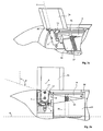
- FIGS. 1a to 3b thus show a first embodiment of a duck deployment device according to the invention.
- the outer shell of the projectile 1 was removed and partial cuts were made to allow visualization of the device.
- the projectile 1 carries four duck wings 2, only one of which is shown in the figures.
- Each fin has a bearing surface 2a which is integral with an arm 2b articulated with respect to a deployment axis 3 which is perpendicular to the axis 4 of the projectile.
- the deployment axis 3 is integral with a drive yoke 5 which is itself pivotally mounted relative to the body 7 of the projectile 1, and along an axis 6, called the control axis, which is one axis at a time. perpendicular to the axis 4 of the projectile and to the axis of deployment 3.
- the fin 2 may pivot about this axis 6, driven by the yoke 5, itself driven by a motor (not shown).
- the drive means of the yoke 5 and the fin 2 are not the subject of the present invention and they will not be described in detail. We can refer to the patent EP1772698 which describes the drive means which is implemented here.
- the deployment device here comprises a first motor means pivoting the duck fin 2 relative to its yoke 5.
- This means is constituted by a spiral spring coaxial with the axis 3 and which has the effect of exerting on the fin 2 a pivoting torque which brings it from its folded position ( Figure la) to its deployed position ( figure 3a ).
- the motor means also comprises another means exerting a pivoting torque on the fin 2.
- This other motor means is constituted by a lever 9 which is pivotally mounted relative to an axis 10 parallel to the axis 3 of deployment of the fin.
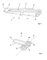
- the figure 4 shows in isolation and in perspective the lever 9.
- the lever comprises two branches 9a, 9b separated by a slot 11 which allows the passage of the bearing surface 2a of the fin 2.
- the branches meet at the end of the lever 9 to form a support finger 12.
- the support finger 12 is in the folded position of the device ( Figures 1a, 1b ), directly in contact with the outer surface of the arm 2b and away from the deployment axis 3.
- two compression springs 13 exert a thrust at a bulge 14 of each leg of the lever 9.
- These springs 13 are just positioned in the figures to locate their location. They are arranged in holes integral with a part of the projectile body. We have shown on figures 2b and 3b the holes by dotted line 15 as well as the part 16 of the projectile body receiving these bores.
- the holes guide the springs 13 during their compression and the bottom of each hole forms a bearing surface for the spring.
- the lever thus completes the torsion spring surrounding the axis 3 and thus provides assistance with the deployment of the fin 2.
- the Figures 2a and 2b show an intermediate step of the deployment of the fin 2.
- the bearing finger 12 follows the outer surface of the wing arm 2b and continues to exert a pair helping to pivot the fin 2 relative to the axis 3.
- the fin 2 comprises a locking means consisting of a slide pin 17 pushed by a spring (not visible in the figures) and which cooperates (in the deployed position of the fin) with a notch 18 ( Figures 1a, 1b and 3a ) carried by the yoke 5.
- the pin 17 is disposed in a housing of the arm 2b of the fin. It is kept erased inside its housing by bearing surfaces integral with the projectile body (and not visible in the figures which include partial sections of the projectile body to see the different organs). The pin 17 enters the notch 18 only when the fin is in the deployed position.
- An obtuse angle ⁇ finally makes it possible to increase the distance between the support zone of the end 12 on the arm 2b and the deployment axis 3. An increase in this distance makes it possible to reduce the angular clearance of the deployed winglet relative to its deployment axis 3.
- the end 12 of the lever 9 secures the lock. Indeed, it prevents any rebound of the fin 2 when it arrives in the deployed position.
- the end 12 of the lever comprises a cylindrical profile 12a which is intended to cooperate with a complementary profile of the arm 2b.
- the arm 2b can rotate freely about the axis 6 once the wing deployed to allow the steering of the projectile.
- the locking abutment formed by the end 12 of the lever 9 does not interfere with the operation of the pilot blade duck 2.
- This detection means is more reliable than the one known hitherto. Indeed it was known to detect the deployment of the fin by a detection of the absence of the fin (exit of the fin outside the projectile body).
- the fin may actually be out of the projectile body without being properly locked in the deployed position.
- the device according to the invention detects, not the exit of the fin from the projectile body, but the locking of this fin.
- the detection is also by locating the position of a metal element (the support finger 12) of relatively small thickness which improves the accuracy of the detection.
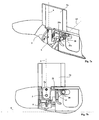
- FIGS. 5a to 7b show a second embodiment of a duck fin deployment device according to the invention.
- This mode differs from the previous one only in the structure of the motor medium.
- This means comprises here (in addition to the spiral carried by the axis 3) a double spiral spring 20.
- This spring is represented alone and in perspective on the figure 8 .
- the spiral portions 20a and 20b are each disposed about an axis 22a, 22b which is disposed in a housing of a portion (not shown) of the projectile body.
- the two axes 22a and 22b are aligned along a geometric axis 23 which is parallel to the axis 3 of deployment of the fin and disposed at a distance from the latter.
- the axes 22a, 22b advantageously comprise a threaded portion cooperating with a tapping of the body and an eccentric portion relative to the threaded portion and which is housed within the spiral portion 20a or 20b considered.
- each axis can move slightly longitudinally each spiral portion.
- Such an arrangement facilitates assembly by allowing a final adjustment of the position of the loop 21 relative to the arm 2b of the fin.
- the free ends 24a, 24b of the spiral portions 20a, 20b are integral with the projectile body.
- the bearing surface 2a of the fin 2 passes between the two spiral portions 20a and 20b.
- the end portion 21a of the loop 21 of the spiral spring 20 is in abutment against the outer surface of the arm 2b of the fin.
- This strand 21a forms the bearing finger which exerts a pivoting torque on the arm 2b of the fin.
- the strand 21a constitutes a locking abutment for the arm 2b of the fin. It can be seen in these figures that the spring 20 in its rest position has its loop 21 substantially parallel to the axis 4 of the projectile. The end portion 21a of the loop 21 is then in contact with the arm 2b.
- End strand 21a is tangent to the outer surface of arm 2b.
- the latter can rotate freely around the axis 6 once the wing deployed to allow the steering of the projectile.
- the locking abutment formed by the end strand 21a of the loop 21 of the spring 20 does not interfere with the operation of the piloting duck fin 2.
- Such an arrangement secures the locking by preventing any bounce of the fin when it arrives in the deployed position.
- the geometric axis 23 of the spring 20 around which are positioned the spiral portions 20a and 20b is located behind the deployment axis 3 of the fin 2 and at a distance from the latter ( figure 7a ). Furthermore, the bearing surface 2a of the fin 2 is housed between the two spiral parts 20a and 20b in the closed position ( Figures 5a and 5b ) and stays between these two spiral parts during deployment ( Figures 6a, 6b ). There is therefore no interference between the spring 20 and the fin during the deployment of the vane and the pivoting thereof around its axis 6 in the deployed position. The only relative contact spring 20 / fin 2 is at the arm 2a by the support of the strand 21a which helps the deployment and ensures a rebound lock.
- an inductive position sensor 19 has been put in place.
- This sensor 19 detects the passage of the loop 21 of the spring 20 to its locking position ( figure 7b ). This accurately and reliably detects the locking of the fin in the deployed position.
- the motor means ensuring deployment without rebound are constituted solely by the lever 9 or by the double hairspring 20.
Landscapes
- Physics & Mathematics (AREA)
- Fluid Mechanics (AREA)
- Engineering & Computer Science (AREA)
- General Engineering & Computer Science (AREA)
- Toys (AREA)
Priority Applications (1)
| Application Number | Priority Date | Filing Date | Title |
|---|---|---|---|
| PL10290479T PL2295928T3 (pl) | 2009-09-10 | 2010-09-08 | Urządzenie do rozkładania i blokowania steru kanardowego |
Applications Claiming Priority (1)
| Application Number | Priority Date | Filing Date | Title |
|---|---|---|---|
| FR0904373A FR2949848B1 (fr) | 2009-09-10 | 2009-09-10 | Dispositif d'ouverture et verrouillage d'une ailette canard. |
Publications (2)
| Publication Number | Publication Date |
|---|---|
| EP2295928A1 true EP2295928A1 (de) | 2011-03-16 |
| EP2295928B1 EP2295928B1 (de) | 2013-03-13 |
Family
ID=42084475
Family Applications (1)
| Application Number | Title | Priority Date | Filing Date |
|---|---|---|---|
| EP10290479A Active EP2295928B1 (de) | 2009-09-10 | 2010-09-08 | Vorrichtung zum Öffnen und Verriegeln eines Canard-Flügels |
Country Status (4)
| Country | Link |
|---|---|
| EP (1) | EP2295928B1 (de) |
| ES (1) | ES2407862T3 (de) |
| FR (1) | FR2949848B1 (de) |
| PL (1) | PL2295928T3 (de) |
Cited By (3)
| Publication number | Priority date | Publication date | Assignee | Title |
|---|---|---|---|---|
| EP2759799A3 (de) * | 2013-01-23 | 2017-07-19 | Simmonds Precision Products, Inc. | System und Vorrichtung zum Halten und ausfahren von Steuerflächen |
| EP3543640A2 (de) | 2018-03-21 | 2019-09-25 | Diehl Defence GmbH & Co. KG | Geschoss mit ausschwenkbaren flügeln und einem gemeinsamen, um die längsachse verdrehbaren arretierbauteil zum lösbaren arretieren der flügel in der eingeschwenkten position |
| WO2022055766A1 (en) * | 2020-09-10 | 2022-03-17 | Bae Systems Information And Electronic Systems Integration Inc. | Additively manufactured elliptical bifurcating torsion spring |
Families Citing this family (1)
| Publication number | Priority date | Publication date | Assignee | Title |
|---|---|---|---|---|
| FR3080912B1 (fr) | 2018-05-02 | 2020-04-03 | Nexter Munitions | Projectile propulse par statoreacteur |
Citations (9)
| Publication number | Priority date | Publication date | Assignee | Title |
|---|---|---|---|---|
| US1330079A (en) * | 1919-08-21 | 1920-02-10 | Kobuchi Luis | Projectile |
| FR2241761A1 (de) | 1973-08-24 | 1975-03-21 | Rheinmetall Gmbh | |
| FR2846080A1 (fr) | 2002-10-17 | 2004-04-23 | Giat Ind Sa | Dispositif de deploiement et d'entrainement de gouvernes de projectile |
| FR2846079A1 (fr) | 2002-10-17 | 2004-04-23 | Giat Ind Sa | Dispositif de verrouillage/deverrouillage et d'entrainement de gouvernes de projectile |
| US6880780B1 (en) * | 2003-03-17 | 2005-04-19 | General Dynamics Ordnance And Tactical Systems, Inc. | Cover ejection and fin deployment system for a gun-launched projectile |
| EP1524488A1 (de) * | 2003-10-06 | 2005-04-20 | Giat Industries | Vorrichtung zum Aufspreizen der Flossen eines Geschosses oder Flugkörpers |
| EP1550837A1 (de) | 2003-12-31 | 2005-07-06 | Giat Industries | Vorrichtung zur Entfaltung und Steuerung der Steuerflächen eines Projektils |
| EP1772698A1 (de) | 2005-10-05 | 2007-04-11 | NEXTER Munitions | Antreibvorrichtung für die Ruder eines Geschosses |
| WO2007133247A2 (en) * | 2005-10-05 | 2007-11-22 | General Dynamics Ordnance And Tactical Systems, Inc. | Fin retention and deployment mechanism |
-
2009
- 2009-09-10 FR FR0904373A patent/FR2949848B1/fr not_active Expired - Fee Related
-
2010
- 2010-09-08 ES ES10290479T patent/ES2407862T3/es active Active
- 2010-09-08 PL PL10290479T patent/PL2295928T3/pl unknown
- 2010-09-08 EP EP10290479A patent/EP2295928B1/de active Active
Patent Citations (9)
| Publication number | Priority date | Publication date | Assignee | Title |
|---|---|---|---|---|
| US1330079A (en) * | 1919-08-21 | 1920-02-10 | Kobuchi Luis | Projectile |
| FR2241761A1 (de) | 1973-08-24 | 1975-03-21 | Rheinmetall Gmbh | |
| FR2846080A1 (fr) | 2002-10-17 | 2004-04-23 | Giat Ind Sa | Dispositif de deploiement et d'entrainement de gouvernes de projectile |
| FR2846079A1 (fr) | 2002-10-17 | 2004-04-23 | Giat Ind Sa | Dispositif de verrouillage/deverrouillage et d'entrainement de gouvernes de projectile |
| US6880780B1 (en) * | 2003-03-17 | 2005-04-19 | General Dynamics Ordnance And Tactical Systems, Inc. | Cover ejection and fin deployment system for a gun-launched projectile |
| EP1524488A1 (de) * | 2003-10-06 | 2005-04-20 | Giat Industries | Vorrichtung zum Aufspreizen der Flossen eines Geschosses oder Flugkörpers |
| EP1550837A1 (de) | 2003-12-31 | 2005-07-06 | Giat Industries | Vorrichtung zur Entfaltung und Steuerung der Steuerflächen eines Projektils |
| EP1772698A1 (de) | 2005-10-05 | 2007-04-11 | NEXTER Munitions | Antreibvorrichtung für die Ruder eines Geschosses |
| WO2007133247A2 (en) * | 2005-10-05 | 2007-11-22 | General Dynamics Ordnance And Tactical Systems, Inc. | Fin retention and deployment mechanism |
Cited By (4)
| Publication number | Priority date | Publication date | Assignee | Title |
|---|---|---|---|---|
| EP2759799A3 (de) * | 2013-01-23 | 2017-07-19 | Simmonds Precision Products, Inc. | System und Vorrichtung zum Halten und ausfahren von Steuerflächen |
| EP3543640A2 (de) | 2018-03-21 | 2019-09-25 | Diehl Defence GmbH & Co. KG | Geschoss mit ausschwenkbaren flügeln und einem gemeinsamen, um die längsachse verdrehbaren arretierbauteil zum lösbaren arretieren der flügel in der eingeschwenkten position |
| WO2022055766A1 (en) * | 2020-09-10 | 2022-03-17 | Bae Systems Information And Electronic Systems Integration Inc. | Additively manufactured elliptical bifurcating torsion spring |
| US11852211B2 (en) | 2020-09-10 | 2023-12-26 | Bae Systems Information And Electronic Systems Integration Inc. | Additively manufactured elliptical bifurcating torsion spring |
Also Published As
| Publication number | Publication date |
|---|---|
| ES2407862T3 (es) | 2013-06-14 |
| FR2949848A1 (fr) | 2011-03-11 |
| PL2295928T3 (pl) | 2013-08-30 |
| FR2949848B1 (fr) | 2012-09-28 |
| EP2295928B1 (de) | 2013-03-13 |
Similar Documents
| Publication | Publication Date | Title |
|---|---|---|
| EP3581742A1 (de) | Motorbetriebene türgriffsteuerung und arbeitsweise | |
| EP2295928B1 (de) | Vorrichtung zum Öffnen und Verriegeln eines Canard-Flügels | |
| EP3561608A1 (de) | Befestigungsleiste eines armbands an einer armbanduhr, die mit zwei einziehbaren drehzapfen ausgestattet ist | |
| EP3980327B1 (de) | Flugzeugtür mit einem hebel zur notöffnung von aussen | |
| EP1738043B1 (de) | Schlüssel mit einklappbarem schaft mit mitteln zum bewegen des schafts in eine ausgeklappte position | |
| FR2958962A1 (fr) | Commande d'ouverture interieure d'un ouvrant de vehicule automobile et vehicule automobile equipee d'une telle commande. | |
| EP1524488B1 (de) | Vorrichtung zum Ausklappen des Leitwerks eines Projektils | |
| EP3030477B1 (de) | Teleskopische federungsvorrichtung mit einem vorspannungsidentifikationssystem | |
| WO2018015367A1 (fr) | Projectile comprenant un dispositif de déploiement d`une voilure ou ailette | |
| EP1745186B1 (de) | Zurückziehbarer einsatzschlüssel mit einsatztreibmitteln | |
| EP2369186B1 (de) | Vierteldrehungs-Befestigungsvorrichtung | |
| EP2522547B1 (de) | Kabelgeführte Leuchtweitenregelungseinrichtung für Scheinwerfer eines Kraftfahrzeugs | |
| EP2104622B1 (de) | Diebstahlsicherungsvorrichtung für ein fahrzeug mit einem eine elastische nase aufweisenden schieber | |
| EP3693593B1 (de) | Turbotriebwerk, das einen antriebsmechanismus eines schubumkehrsystems umfasst | |
| FR3067515A1 (fr) | Interrupteur, en particulier pour le levier de la pedale de frein d'un vehicule | |
| EP2640915B1 (de) | Handgriff für ein fahrzeug mit blockierendem trägheitskörper mit einem gegengewicht | |
| EP0769598A1 (de) | Schloss vom Typ eines entkuppelbaren Rotors | |
| EP3182433B1 (de) | Federführungsvorrichtung in einem betätigungsmechanismus und damit versehenes elektrisches schutzgerät | |
| FR2874251A1 (fr) | Systeme de deploiement de plan aerodynamique | |
| FR3014937B1 (fr) | Fin de course d'enroulement ou de deroulement de tablier de systeme d'occultation | |
| EP0775605B1 (de) | Sonnenschutzrolle mit Entfaltungsmechanismus durch Schwungstangen | |
| EP3269917A1 (de) | Automatische verriegelungsvorrichtung einer rollladenbahn eines verdunkelungssystems | |
| EP0731006B1 (de) | Lenkradschloss für Kraftfahrzeug | |
| EP0769597A1 (de) | Schloss vom Typ eines entkuppelbaren Rotors | |
| EP2174813A1 (de) | Seitliche Fahrzeugschiebetür mit einer einziehbaren Armlehne |
Legal Events
| Date | Code | Title | Description |
|---|---|---|---|
| PUAI | Public reference made under article 153(3) epc to a published international application that has entered the european phase |
Free format text: ORIGINAL CODE: 0009012 |
|
| AK | Designated contracting states |
Kind code of ref document: A1 Designated state(s): AL AT BE BG CH CY CZ DE DK EE ES FI FR GB GR HR HU IE IS IT LI LT LU LV MC MK MT NL NO PL PT RO SE SI SK SM TR |
|
| AX | Request for extension of the european patent |
Extension state: BA ME RS |
|
| 17P | Request for examination filed |
Effective date: 20110916 |
|
| GRAP | Despatch of communication of intention to grant a patent |
Free format text: ORIGINAL CODE: EPIDOSNIGR1 |
|
| GRAS | Grant fee paid |
Free format text: ORIGINAL CODE: EPIDOSNIGR3 |
|
| GRAA | (expected) grant |
Free format text: ORIGINAL CODE: 0009210 |
|
| AK | Designated contracting states |
Kind code of ref document: B1 Designated state(s): AL AT BE BG CH CY CZ DE DK EE ES FI FR GB GR HR HU IE IS IT LI LT LU LV MC MK MT NL NO PL PT RO SE SI SK SM TR |
|
| REG | Reference to a national code |
Ref country code: GB Ref legal event code: FG4D Free format text: NOT ENGLISH |
|
| REG | Reference to a national code |
Ref country code: CH Ref legal event code: EP Ref country code: AT Ref legal event code: REF Ref document number: 601059 Country of ref document: AT Kind code of ref document: T Effective date: 20130315 |
|
| REG | Reference to a national code |
Ref country code: IE Ref legal event code: FG4D Free format text: LANGUAGE OF EP DOCUMENT: FRENCH |
|
| REG | Reference to a national code |
Ref country code: DE Ref legal event code: R096 Ref document number: 602010005433 Country of ref document: DE Effective date: 20130508 |
|
| REG | Reference to a national code |
Ref country code: ES Ref legal event code: FG2A Ref document number: 2407862 Country of ref document: ES Kind code of ref document: T3 Effective date: 20130614 |
|
| REG | Reference to a national code |
Ref country code: SE Ref legal event code: TRGR |
|
| REG | Reference to a national code |
Ref country code: NO Ref legal event code: T2 Effective date: 20130313 |
|
| PG25 | Lapsed in a contracting state [announced via postgrant information from national office to epo] |
Ref country code: LT Free format text: LAPSE BECAUSE OF FAILURE TO SUBMIT A TRANSLATION OF THE DESCRIPTION OR TO PAY THE FEE WITHIN THE PRESCRIBED TIME-LIMIT Effective date: 20130313 Ref country code: BG Free format text: LAPSE BECAUSE OF FAILURE TO SUBMIT A TRANSLATION OF THE DESCRIPTION OR TO PAY THE FEE WITHIN THE PRESCRIBED TIME-LIMIT Effective date: 20130613 |
|
| REG | Reference to a national code |
Ref country code: AT Ref legal event code: MK05 Ref document number: 601059 Country of ref document: AT Kind code of ref document: T Effective date: 20130313 |
|
| REG | Reference to a national code |
Ref country code: NL Ref legal event code: VDEP Effective date: 20130313 |
|
| REG | Reference to a national code |
Ref country code: LT Ref legal event code: MG4D |
|
| PG25 | Lapsed in a contracting state [announced via postgrant information from national office to epo] |
Ref country code: LV Free format text: LAPSE BECAUSE OF FAILURE TO SUBMIT A TRANSLATION OF THE DESCRIPTION OR TO PAY THE FEE WITHIN THE PRESCRIBED TIME-LIMIT Effective date: 20130313 Ref country code: FI Free format text: LAPSE BECAUSE OF FAILURE TO SUBMIT A TRANSLATION OF THE DESCRIPTION OR TO PAY THE FEE WITHIN THE PRESCRIBED TIME-LIMIT Effective date: 20130313 Ref country code: SI Free format text: LAPSE BECAUSE OF FAILURE TO SUBMIT A TRANSLATION OF THE DESCRIPTION OR TO PAY THE FEE WITHIN THE PRESCRIBED TIME-LIMIT Effective date: 20130313 Ref country code: GR Free format text: LAPSE BECAUSE OF FAILURE TO SUBMIT A TRANSLATION OF THE DESCRIPTION OR TO PAY THE FEE WITHIN THE PRESCRIBED TIME-LIMIT Effective date: 20130614 |
|
| REG | Reference to a national code |
Ref country code: PL Ref legal event code: T3 |
|
| PG25 | Lapsed in a contracting state [announced via postgrant information from national office to epo] |
Ref country code: HR Free format text: LAPSE BECAUSE OF FAILURE TO SUBMIT A TRANSLATION OF THE DESCRIPTION OR TO PAY THE FEE WITHIN THE PRESCRIBED TIME-LIMIT Effective date: 20130313 |
|
| PG25 | Lapsed in a contracting state [announced via postgrant information from national office to epo] |
Ref country code: CZ Free format text: LAPSE BECAUSE OF FAILURE TO SUBMIT A TRANSLATION OF THE DESCRIPTION OR TO PAY THE FEE WITHIN THE PRESCRIBED TIME-LIMIT Effective date: 20130313 Ref country code: IS Free format text: LAPSE BECAUSE OF FAILURE TO SUBMIT A TRANSLATION OF THE DESCRIPTION OR TO PAY THE FEE WITHIN THE PRESCRIBED TIME-LIMIT Effective date: 20130713 Ref country code: NL Free format text: LAPSE BECAUSE OF FAILURE TO SUBMIT A TRANSLATION OF THE DESCRIPTION OR TO PAY THE FEE WITHIN THE PRESCRIBED TIME-LIMIT Effective date: 20130313 Ref country code: EE Free format text: LAPSE BECAUSE OF FAILURE TO SUBMIT A TRANSLATION OF THE DESCRIPTION OR TO PAY THE FEE WITHIN THE PRESCRIBED TIME-LIMIT Effective date: 20130313 Ref country code: AT Free format text: LAPSE BECAUSE OF FAILURE TO SUBMIT A TRANSLATION OF THE DESCRIPTION OR TO PAY THE FEE WITHIN THE PRESCRIBED TIME-LIMIT Effective date: 20130313 Ref country code: RO Free format text: LAPSE BECAUSE OF FAILURE TO SUBMIT A TRANSLATION OF THE DESCRIPTION OR TO PAY THE FEE WITHIN THE PRESCRIBED TIME-LIMIT Effective date: 20130313 Ref country code: PT Free format text: LAPSE BECAUSE OF FAILURE TO SUBMIT A TRANSLATION OF THE DESCRIPTION OR TO PAY THE FEE WITHIN THE PRESCRIBED TIME-LIMIT Effective date: 20130715 Ref country code: SK Free format text: LAPSE BECAUSE OF FAILURE TO SUBMIT A TRANSLATION OF THE DESCRIPTION OR TO PAY THE FEE WITHIN THE PRESCRIBED TIME-LIMIT Effective date: 20130313 |
|
| PLBE | No opposition filed within time limit |
Free format text: ORIGINAL CODE: 0009261 |
|
| STAA | Information on the status of an ep patent application or granted ep patent |
Free format text: STATUS: NO OPPOSITION FILED WITHIN TIME LIMIT |
|
| PG25 | Lapsed in a contracting state [announced via postgrant information from national office to epo] |
Ref country code: DK Free format text: LAPSE BECAUSE OF FAILURE TO SUBMIT A TRANSLATION OF THE DESCRIPTION OR TO PAY THE FEE WITHIN THE PRESCRIBED TIME-LIMIT Effective date: 20130313 |
|
| 26N | No opposition filed |
Effective date: 20131216 |
|
| REG | Reference to a national code |
Ref country code: DE Ref legal event code: R097 Ref document number: 602010005433 Country of ref document: DE Effective date: 20131216 |
|
| PG25 | Lapsed in a contracting state [announced via postgrant information from national office to epo] |
Ref country code: MC Free format text: LAPSE BECAUSE OF FAILURE TO SUBMIT A TRANSLATION OF THE DESCRIPTION OR TO PAY THE FEE WITHIN THE PRESCRIBED TIME-LIMIT Effective date: 20130313 |
|
| REG | Reference to a national code |
Ref country code: IE Ref legal event code: MM4A |
|
| PG25 | Lapsed in a contracting state [announced via postgrant information from national office to epo] |
Ref country code: IE Free format text: LAPSE BECAUSE OF NON-PAYMENT OF DUE FEES Effective date: 20130908 |
|
| REG | Reference to a national code |
Ref country code: CH Ref legal event code: PL |
|
| PG25 | Lapsed in a contracting state [announced via postgrant information from national office to epo] |
Ref country code: SM Free format text: LAPSE BECAUSE OF FAILURE TO SUBMIT A TRANSLATION OF THE DESCRIPTION OR TO PAY THE FEE WITHIN THE PRESCRIBED TIME-LIMIT Effective date: 20130313 |
|
| PG25 | Lapsed in a contracting state [announced via postgrant information from national office to epo] |
Ref country code: MT Free format text: LAPSE BECAUSE OF FAILURE TO SUBMIT A TRANSLATION OF THE DESCRIPTION OR TO PAY THE FEE WITHIN THE PRESCRIBED TIME-LIMIT Effective date: 20130313 Ref country code: CY Free format text: LAPSE BECAUSE OF FAILURE TO SUBMIT A TRANSLATION OF THE DESCRIPTION OR TO PAY THE FEE WITHIN THE PRESCRIBED TIME-LIMIT Effective date: 20130313 Ref country code: TR Free format text: LAPSE BECAUSE OF FAILURE TO SUBMIT A TRANSLATION OF THE DESCRIPTION OR TO PAY THE FEE WITHIN THE PRESCRIBED TIME-LIMIT Effective date: 20130313 |
|
| PG25 | Lapsed in a contracting state [announced via postgrant information from national office to epo] |
Ref country code: LI Free format text: LAPSE BECAUSE OF NON-PAYMENT OF DUE FEES Effective date: 20140930 Ref country code: MK Free format text: LAPSE BECAUSE OF FAILURE TO SUBMIT A TRANSLATION OF THE DESCRIPTION OR TO PAY THE FEE WITHIN THE PRESCRIBED TIME-LIMIT Effective date: 20130313 Ref country code: CH Free format text: LAPSE BECAUSE OF NON-PAYMENT OF DUE FEES Effective date: 20140930 Ref country code: LU Free format text: LAPSE BECAUSE OF NON-PAYMENT OF DUE FEES Effective date: 20130908 Ref country code: HU Free format text: LAPSE BECAUSE OF FAILURE TO SUBMIT A TRANSLATION OF THE DESCRIPTION OR TO PAY THE FEE WITHIN THE PRESCRIBED TIME-LIMIT; INVALID AB INITIO Effective date: 20100908 |
|
| REG | Reference to a national code |
Ref country code: FR Ref legal event code: PLFP Year of fee payment: 7 |
|
| REG | Reference to a national code |
Ref country code: FR Ref legal event code: PLFP Year of fee payment: 8 |
|
| REG | Reference to a national code |
Ref country code: FR Ref legal event code: PLFP Year of fee payment: 9 |
|
| PG25 | Lapsed in a contracting state [announced via postgrant information from national office to epo] |
Ref country code: AL Free format text: LAPSE BECAUSE OF FAILURE TO SUBMIT A TRANSLATION OF THE DESCRIPTION OR TO PAY THE FEE WITHIN THE PRESCRIBED TIME-LIMIT Effective date: 20130313 |
|
| PGFP | Annual fee paid to national office [announced via postgrant information from national office to epo] |
Ref country code: DE Payment date: 20250820 Year of fee payment: 16 |
|
| PGFP | Annual fee paid to national office [announced via postgrant information from national office to epo] |
Ref country code: NO Payment date: 20250825 Year of fee payment: 16 |
|
| PGFP | Annual fee paid to national office [announced via postgrant information from national office to epo] |
Ref country code: IT Payment date: 20250820 Year of fee payment: 16 Ref country code: PL Payment date: 20250825 Year of fee payment: 16 |
|
| PGFP | Annual fee paid to national office [announced via postgrant information from national office to epo] |
Ref country code: BE Payment date: 20250820 Year of fee payment: 16 Ref country code: GB Payment date: 20250822 Year of fee payment: 16 |
|
| PGFP | Annual fee paid to national office [announced via postgrant information from national office to epo] |
Ref country code: FR Payment date: 20250820 Year of fee payment: 16 |
|
| PGFP | Annual fee paid to national office [announced via postgrant information from national office to epo] |
Ref country code: SE Payment date: 20250820 Year of fee payment: 16 |
|
| PGFP | Annual fee paid to national office [announced via postgrant information from national office to epo] |
Ref country code: ES Payment date: 20251001 Year of fee payment: 16 |