EP2296019A1 - Commutateur électrique optique - Google Patents
Commutateur électrique optique Download PDFInfo
- Publication number
- EP2296019A1 EP2296019A1 EP09170178A EP09170178A EP2296019A1 EP 2296019 A1 EP2296019 A1 EP 2296019A1 EP 09170178 A EP09170178 A EP 09170178A EP 09170178 A EP09170178 A EP 09170178A EP 2296019 A1 EP2296019 A1 EP 2296019A1
- Authority
- EP
- European Patent Office
- Prior art keywords
- optical
- ops
- soft material
- optical element
- ops device
- Prior art date
- Legal status (The legal status is an assumption and is not a legal conclusion. Google has not performed a legal analysis and makes no representation as to the accuracy of the status listed.)
- Withdrawn
Links
- 230000003287 optical effect Effects 0.000 title claims abstract description 156
- 239000007779 soft material Substances 0.000 claims abstract description 46
- 239000000463 material Substances 0.000 claims description 13
- 239000011521 glass Substances 0.000 abstract description 11
- 239000012780 transparent material Substances 0.000 abstract description 11
- 230000001419 dependent effect Effects 0.000 description 7
- 230000003213 activating effect Effects 0.000 description 5
- 238000006073 displacement reaction Methods 0.000 description 4
- 230000005540 biological transmission Effects 0.000 description 3
- 230000004075 alteration Effects 0.000 description 2
- 230000001788 irregular Effects 0.000 description 2
- 230000004913 activation Effects 0.000 description 1
- 230000000712 assembly Effects 0.000 description 1
- 238000000429 assembly Methods 0.000 description 1
- 230000001276 controlling effect Effects 0.000 description 1
- 239000004973 liquid crystal related substance Substances 0.000 description 1
- VZUGBLTVBZJZOE-KRWDZBQOSA-N n-[3-[(4s)-2-amino-1,4-dimethyl-6-oxo-5h-pyrimidin-4-yl]phenyl]-5-chloropyrimidine-2-carboxamide Chemical compound N1=C(N)N(C)C(=O)C[C@@]1(C)C1=CC=CC(NC(=O)C=2N=CC(Cl)=CN=2)=C1 VZUGBLTVBZJZOE-KRWDZBQOSA-N 0.000 description 1
- 239000013307 optical fiber Substances 0.000 description 1
- 230000001105 regulatory effect Effects 0.000 description 1
- 238000009736 wetting Methods 0.000 description 1
Images




Classifications
-
- G—PHYSICS
- G02—OPTICS
- G02B—OPTICAL ELEMENTS, SYSTEMS OR APPARATUS
- G02B26/00—Optical devices or arrangements for the control of light using movable or deformable optical elements
- G02B26/02—Optical devices or arrangements for the control of light using movable or deformable optical elements for controlling the intensity of light
-
- G—PHYSICS
- G02—OPTICS
- G02B—OPTICAL ELEMENTS, SYSTEMS OR APPARATUS
- G02B26/00—Optical devices or arrangements for the control of light using movable or deformable optical elements
- G02B26/06—Optical devices or arrangements for the control of light using movable or deformable optical elements for controlling the phase of light
-
- G—PHYSICS
- G02—OPTICS
- G02B—OPTICAL ELEMENTS, SYSTEMS OR APPARATUS
- G02B3/00—Simple or compound lenses
-
- G—PHYSICS
- G02—OPTICS
- G02B—OPTICAL ELEMENTS, SYSTEMS OR APPARATUS
- G02B3/00—Simple or compound lenses
- G02B3/12—Fluid-filled or evacuated lenses
- G02B3/14—Fluid-filled or evacuated lenses of variable focal length
-
- G—PHYSICS
- G02—OPTICS
- G02B—OPTICAL ELEMENTS, SYSTEMS OR APPARATUS
- G02B7/00—Mountings, adjusting means, or light-tight connections, for optical elements
- G02B7/02—Mountings, adjusting means, or light-tight connections, for optical elements for lenses
- G02B7/028—Mountings, adjusting means, or light-tight connections, for optical elements for lenses with means for compensating for changes in temperature or for controlling the temperature; thermal stabilisation
Definitions
- the present invention is generally related to the field of optical systems and/or lens attachments, and more specific to an optical system and/or lens attachment providing an Optical Power Switch (OPS) controllably switchable by controllably adapting a soft transparent material element as part of a lens or lens attachment or another type of optical element in an optical system.
- OPS Optical Power Switch
- TDG Tuneable Diffraction Grating
- an improved OPS device would be advantageous, and in particular a more efficient and/or reliable OPS device would be advantageous.
- OPS device comprising optical components providing switching of relatively high optical power, > 20 dpt, with small mechanical movements.
- lens profiles will be substantially preserved during operation of OPS devices according to the present invention.
- an OPS device comprising functionality for deactivating and/or activating or changing parameter values for optical features of an optical element surface (for example a lens surface) intersecting an optical axis in the optical system by pushing and/or withdrawing a soft optical material element like e.g. silicone-gel respectively to and from the surface of the optical element (lens).
- an optical element surface for example a lens surface
- a soft optical material element like e.g. silicone-gel respectively to and from the surface of the optical element (lens).
- an optical element can be switched between an "on” state and an "off” state for light passing through the optical element.
- the optical element can switch a focal distance between a first defined value and a second defined value for the focal length.
- the switching of the OPS according to the present invention provides an optical zoom system.
- the switching of the OPS according to the present invention provides an optical macro system.
- the soft material element for example the silicone-gel
- the soft material element material for example a lens material
- the optical power can be switched and reduced substantially towards zero.
- the soft material element for example the silicone-gel
- the soft material element material for example a lens material
- the optical power can be switched between a first defined level and a second defined value dependent on which state of contact there is between the optical element and the transparent soft material element, for example full contacting or no contact at all, or the amount of areal overlap there is in the contact area between the optical element surface and the transparent soft material element surface.
- a lens body is made of a soft transparent material, for example silicone-gel, and is controllably pushed respectively withdrawn from a glass plate. Further, in a variant, the glass plate is pushed respectively withdrawn from the lens body.
- the lens body can be any type of optical element.
- a lens body is a scattering surface. When the scattering surface is pushed into contact with a soft transparent material element surface, the optical element in contact with the soft material element becomes a light transmitting element.
- the lens body is an optical element comprising an irregular surface, for example a saw-tooth shaped surface, a rugged surface etc. that is respectively pushed into or withdrawn from contact with the soft transparent material element, thereby providing a different transmission of light through the optical system dependent on which state of contact there is between the optical element and the transparent soft material element, for example full contact or no contact at all, or the amount of areal overlap there is in the contacting area between the optical element surface and the transparent soft material element surface.
- an irregular surface for example a saw-tooth shaped surface, a rugged surface etc.
- the optical element is a Fresnel lens.
- the optical element and the soft material element has parallel surfaces.
- the optical element is a prism with a non-parallel surface relative to a contact surface of the soft material element. This provides a change of direction of light passing through the optical system dependent on which state of contact there is between the optical element and the transparent soft material element, for example full contact or no contact at all, or the amount of areal overlap there is in the contact area between the optical element surface and the transparent soft material element surface.
- the optical element and the soft material element has parallel surface, but are not oriented perpendicular to the optical axis through the optical system. This provides a parallel shift of light passing through the optical system dependent on which state of contact there is between the optical element and the transparent soft material element, for example full contact or no contact at all, or the amount of areal overlap there is in the contact area between the optical element surface and the transparent soft material element surface.
- the individual elements of an embodiment according to the present invention may be physically, functionally and logically implemented in any suitable way such as in a single unit, in a plurality of units or as part of separate functional units.
- the present invention may be implemented in a single unit, or be both physically and functionally distributed between different units.
- An aspect of the present invent is to provide an OPS device comprising functionality for deactivating and/or activating or changing parameter values for optical features of an optical element surface (for example a lens surface) intersecting an optical axis in the optical system by pushing and/or withdrawing a soft optical material element like e.g. silicone-gel respectively to and from the surface of the optical element (lens).
- an optical element surface for example a lens surface
- a soft optical material element like e.g. silicone-gel respectively to and from the surface of the optical element (lens).
- an OPS device for by changing a surface shape of a lens, for example by levelling out a curved shape of a lens surface with for example a soft transparent material element, for example a transparent silicone-gel element, for example a cubic formed slice of a piece of a soft but cured silicone-gel element.
- This slice of soft silicone-gel can be deposited onto an optical transparent glass plate and be cured and remain soft after curing as known to a person skilled in the art.
- a lens body 10 is located in front of an element of silicone-gel (or soft material element) 12 deposited onto a glass plate 11.
- the operation of the Optical Power Switch (OPS) according to the present invention is to move the glass plate 11 towards the lens body 10, for example by activating actuators with respective control signals, wherein the soft silicone-gel 12 is facing towards a curved surface of the lens body 10, wherein the surface of the lens body 10 intersects an optical axis of the lens body 10.
- OPS Optical Power Switch
- optical effect of this condition is that the optical power of light passing through the lens assembly in figure 1 is substantially zero.
- the optical power of light passing through the lens assembly in figure 1 is defined by the optical properties of the total lens assembly the light is passing through and which the OPS system is part of.
- the amount of overlapping of the surface contact areas between the lens body surface 10 and the surface of the soft silicone-gel element 12 has an optical effect on the optical power of the light passing through the lens assembly.
- the value of the optical power of the light that passes is proportional to the amount of areal overlapping in the contact surface between the respective surfaces of the lens body 10 and the surface of the silicone-gel 12. Therefore, it is possible to tune the amount of optical power of the light passing through the lens assembly between a respective first level and a second level.
- the first optical power level and the second optical power level as described above is equivalent to turning the OPS "on” or "off", respectively.
- the OPS will switch between a respective first defined optical power level and a second defined optical power level. This is also equivalent to switch the lens assembly between a defined respective first focal length and a second focal length, respectively. It is also obvious from the description above that it is possible to control the focal length between the first defined value and the second value just by controlling the amount of areal overlapping there is in the contact surface between the surfaces of the optical lens body 10 and the soft material element or silicone-gel element 12.
- a macro optical system is a term used when an optical system should be able to focus on objects very close to the optical system.
- D lens 2mm
- H lens R lens - SQRT ( R lens 2 - D lens / 2 2
- H lens is the height of the lens
- R lens is the radius of the lens body element
- D lens is the diameter of the OPS element.
- R lens 1 / 1 / ⁇ - 1 • 1 / f ⁇ is the refractive index of the lens body material.
- the soft material element 12 for example a silicone-gel element
- the soft material element 12 will have a thermal expansion. Therefore it is necessary to compensate for the coefficient of thermal expansion for the material in use, for example the coefficient for the silicone-gel material at room temperature that is used and the temperature range that is expected to be present when using the optical element.
- an operational environment with a Room Temperature RT +/-40 C° makes it necessary to add a certain additional value to the H lens parameter.
- the additional space necessary to provide compensation for the thermal expansion of a 100 ⁇ m gel layer at these operational conditions is 0,006mm. Therefore a movement of only 26 ⁇ m is necessary to provide a switching of states for the OPS between "on" or "off” respectively for a 50 mm macro lens assembly within a temperature range of for example -20 C° to + 60 C°.
- MEMS Micro Electrical Mechanical System
- Piezo electric actuator systems Piezo electric actuator systems
- FIG. 3 An example of use of an OPS macro according to the present invention is depicted in figure 3 .
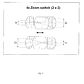
- FIG 4 Another example of use of an OPS device according to the present invention is illustrated in figure 4 .
- This example illustrates how an OPS device according to the present invention can be used to control zooming operations in a lens assembly.
- the optical feature of the prism lens used in between the two OPS elements according to the present invention is known to a person skilled in the art.
- the function of the OPS is to switch "on” or “off” the zooming quantity given by the lens assembly.
- the controllable areal overlapping in the contacting surface between the OPS and the optical prism element in the middle makes it possible to adjust the amount of zooming, and not only switch “on” or “off” the zooming property.
- Figure 6 illustrates that it is also possible to use concave shaped lens surfaces (contrary to the convex example in figure 1 ) in the lens body in an OPS according to the present invention.
- concave shaped lens surfaces (contrary to the convex example in figure 1 ) in the lens body in an OPS according to the present invention.
- this example of embodiment depicted in figure 6 there is also arranged a micro hole in the centre of the concave shaped lens body element.
- any air or gas trapped in between the soft material element and the concave shaped surface of the lens body will escape through this arranged micro hole.
- Figure 7 illustrates an example of embodiment of a stacked OPS device according to the present invention.
- OPS element can be used in the optical system, for example stacked as illustrated in figure 7 .
- Figure 8 illustrates how MEMS actuators can be used in an OPS device according to the present invention.
- the illustration to the left depicts the arrangement of the actuators and the moving parts of the OPS. The movement is perpendicular to the paper surface.
- the illustration to the right is a cross section view of the OPS.
- a lens body is made of a soft transparent material, for example silicone-gel, and is controllably pushed respectively withdrawn form a glass plate, for example by activating actuators. Further, in a variant, the glass plate is pushed respectively withdrawn from the soft lens body.
- the lens body can be any type of optical element.
- a lens body is a scattering surface. When the scattering surface is pushed into contact with a soft transparent material element the optical element in contact with the soft material element becomes in a light transmitting element.
- the lens body is an optical element comprising an irregular surface, for example a saw-tooth shaped surface, a rugged surface etc. that is respectively pushed into or withdrawn from contact with the soft transparent material element, thereby providing a different transmission of light through the optical system dependent on which state of contact there is between the optical element and the transparent soft material element, for example full contact or no contact at all, or the amount of areal overlap there is in the contacting area between the optical element surface and the transparent soft material element surface.
- an irregular surface for example a saw-tooth shaped surface, a rugged surface etc.
- the optical element is a Fresnel lens.
- the optical element and the soft material element has parallel surfaces.
- the optical element is a prism with a non-parallel surface relative to a contact surface of the soft material element. This provides a change of direction of light passing through the optical system dependent on which state of contact there is between the optical element and the transparent soft material element, for example full contact or no contact at all, or the amount of areal overlap there is in the contacting area between the optical element surface and the transparent soft material element surface.
- the optical element and the soft material element has parallel surfaces, but are not oriented perpendicular onto the optical axis of the light transmission through the optical system.
- This provides a parallel shift of light passing through the optical system dependent on which state of contact there is between the optical element and the transparent soft material element, for example full contact or no contact at all, or the amount of areal overlap there is in the contacting area between the optical element surface and the transparent soft material element surface.
- a micro controller or micro processor system For example, a mobile phone, a digital camera etc. has computing resources that can be programmed to provide a correct voltage level for activating a specific actuator type or design.
- a simple geometrical model of the surface of the optical element and the surface of the transparent material element may be used to identify the amount of movement that is necessary to provide in the system to achieve a certain level of areal overlapping.
- the type of actuator that is actually in use will then have a known relationship between applied voltage and displacement provided for by the actuator, and hence the necessary specific voltage that has to be applied on the actuator for a certain movement is identified correctly. This relationship can for example be stored in a look up table the computing element or processor can read from.
- the table can be indexed by numerical values indicating respective displacements, and in each indexed storage location a numerical value corresponding to the necessary voltage value to achieve the displacement is stored.
- the computing element or processing element can transfer this value via signals directly to actuators if they are digitally controllable, or transfer the value to a digital-to-analogue converter if the actuators are of analogue type.
- the numerical span of the displacement values can correspond to the numerical span defining an "off" state to an "on” state as described above. When moving between these two states the computing element or processor element can move through all the indexes of the table in a successive manner. This will accomplish a switching of the state of the OPS controlled in this manner in this example of embodiment. If a smooth movement is necessary, electronic filters used to filter the control signals, the speed the computing element or processor use when reading from the table can be used to control any aspect of the movements in an OPS system according to this example of embodiment of the present invention.
- the computing element or processor receives information, for example a message or signal, instructing the computing element or processor to put the OPS device according to the present invention in a certain state, wherein the state is as described above.
- information for example a message or signal
- the computing element or processor receives information, for example a message or signal, instructing the computing element or processor to put the OPS device according to the present invention in a certain state, wherein the state is as described above.
- signals generated elsewhere in the optical system can control the OPS device, for example as direct control signals or as a result of feedback conditions in a regulating loop feedback system.
- the OPS device according to the present invention is a versatile, simple and robust optical device that can be used alone or in combination with any type of optical components used in an optical system assembly.
- Such optical systems or assemblies may comprise only one OPS device according to the present invention, a plurality of such OPS devices that are stacked or are individually positioned inside the optical system or optical assembly, intersecting for example one or a plurality of optical axis in the optical system or assembly.
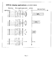
- some examples of applications of the OPS device is described. However, these examples do not limit the scope of application of the OPS according to the present invention.
- an OPS device can be used as a Variable Optical attenuator, for example in an optical fibre communication system.
Landscapes
- Physics & Mathematics (AREA)
- General Physics & Mathematics (AREA)
- Optics & Photonics (AREA)
- Mechanical Light Control Or Optical Switches (AREA)
- Lens Barrels (AREA)
- Micromachines (AREA)
Priority Applications (7)
| Application Number | Priority Date | Filing Date | Title |
|---|---|---|---|
| EP09170178A EP2296019A1 (fr) | 2009-09-14 | 2009-09-14 | Commutateur électrique optique |
| KR1020127009547A KR101705395B1 (ko) | 2009-09-14 | 2010-09-13 | 광학 배율 스위치(ops) |
| JP2012528381A JP5756464B2 (ja) | 2009-09-14 | 2010-09-13 | 光学パワースイッチ |
| EP10751695A EP2478392A1 (fr) | 2009-09-14 | 2010-09-13 | Commutateur de puissance optique (ops) |
| PCT/EP2010/063391 WO2011029932A1 (fr) | 2009-09-14 | 2010-09-13 | Commutateur de puissance optique (ops) |
| CN201080041095.1A CN102597816B (zh) | 2009-09-14 | 2010-09-13 | 光功率开关(ops) |
| US13/496,178 US8724198B2 (en) | 2009-09-14 | 2010-09-13 | Optical power switch (OPS) |
Applications Claiming Priority (1)
| Application Number | Priority Date | Filing Date | Title |
|---|---|---|---|
| EP09170178A EP2296019A1 (fr) | 2009-09-14 | 2009-09-14 | Commutateur électrique optique |
Publications (1)
| Publication Number | Publication Date |
|---|---|
| EP2296019A1 true EP2296019A1 (fr) | 2011-03-16 |
Family
ID=41571879
Family Applications (2)
| Application Number | Title | Priority Date | Filing Date |
|---|---|---|---|
| EP09170178A Withdrawn EP2296019A1 (fr) | 2009-09-14 | 2009-09-14 | Commutateur électrique optique |
| EP10751695A Withdrawn EP2478392A1 (fr) | 2009-09-14 | 2010-09-13 | Commutateur de puissance optique (ops) |
Family Applications After (1)
| Application Number | Title | Priority Date | Filing Date |
|---|---|---|---|
| EP10751695A Withdrawn EP2478392A1 (fr) | 2009-09-14 | 2010-09-13 | Commutateur de puissance optique (ops) |
Country Status (6)
| Country | Link |
|---|---|
| US (1) | US8724198B2 (fr) |
| EP (2) | EP2296019A1 (fr) |
| JP (1) | JP5756464B2 (fr) |
| KR (1) | KR101705395B1 (fr) |
| CN (1) | CN102597816B (fr) |
| WO (1) | WO2011029932A1 (fr) |
Cited By (2)
| Publication number | Priority date | Publication date | Assignee | Title |
|---|---|---|---|---|
| KR20170042659A (ko) * | 2014-08-08 | 2017-04-19 | 탠텀 옵틱스 엘엘씨 | 매크로 렌즈 |
| WO2018197556A1 (fr) * | 2017-04-26 | 2018-11-01 | Carl Zeiss Microscopy Gmbh | Procédé et dispositif servant à réguler des intensités incidentes dans un diaphragme perforé et/ou des fractions spectrales d'un rayonnement |
Families Citing this family (3)
| Publication number | Priority date | Publication date | Assignee | Title |
|---|---|---|---|---|
| US8651916B2 (en) * | 2010-01-18 | 2014-02-18 | Disney Enterprises, Inc. | System and method for generating realistic eyes |
| EP3908864A1 (fr) * | 2019-01-08 | 2021-11-17 | Optotune AG | Dispositif optique comprenant une compensation passive de température |
| CA3191076A1 (fr) * | 2021-01-21 | 2022-01-20 | Conexus Lens, Inc. | Reduction des effets provoques par la formation de multiples foyers dans une lentille deformable pendant des changements d'aplanation de surfaces de celle-ci |
Citations (4)
| Publication number | Priority date | Publication date | Assignee | Title |
|---|---|---|---|---|
| US6288846B1 (en) * | 1999-09-24 | 2001-09-11 | Arizona Carbon Foil Co., Inc. | Variable focal-length lens assembly |
| US20040179259A1 (en) * | 2003-03-11 | 2004-09-16 | Fuji Photo Film Co., Ltd. | Display device |
| US6897995B2 (en) | 2002-09-06 | 2005-05-24 | Photonyx As | Method and device for variable optical attenuator |
| US20060152646A1 (en) | 2002-08-21 | 2006-07-13 | Martin Schrader | Switchable lens display |
Family Cites Families (4)
| Publication number | Priority date | Publication date | Assignee | Title |
|---|---|---|---|---|
| JPH11142608A (ja) * | 1997-11-12 | 1999-05-28 | Canon Inc | 光学素子とその製造方法 |
| JP4345123B2 (ja) * | 1999-02-24 | 2009-10-14 | 株式会社ニコン | 樹脂接合型光学素子とその製造方法 |
| JP2004295087A (ja) * | 2003-03-11 | 2004-10-21 | Fuji Photo Film Co Ltd | 表示装置 |
| JP2005099154A (ja) * | 2003-09-22 | 2005-04-14 | Toshiba Corp | 光スイッチ |
-
2009
- 2009-09-14 EP EP09170178A patent/EP2296019A1/fr not_active Withdrawn
-
2010
- 2010-09-13 US US13/496,178 patent/US8724198B2/en not_active Expired - Fee Related
- 2010-09-13 JP JP2012528381A patent/JP5756464B2/ja not_active Expired - Fee Related
- 2010-09-13 EP EP10751695A patent/EP2478392A1/fr not_active Withdrawn
- 2010-09-13 WO PCT/EP2010/063391 patent/WO2011029932A1/fr not_active Ceased
- 2010-09-13 CN CN201080041095.1A patent/CN102597816B/zh not_active Expired - Fee Related
- 2010-09-13 KR KR1020127009547A patent/KR101705395B1/ko not_active Expired - Fee Related
Patent Citations (4)
| Publication number | Priority date | Publication date | Assignee | Title |
|---|---|---|---|---|
| US6288846B1 (en) * | 1999-09-24 | 2001-09-11 | Arizona Carbon Foil Co., Inc. | Variable focal-length lens assembly |
| US20060152646A1 (en) | 2002-08-21 | 2006-07-13 | Martin Schrader | Switchable lens display |
| US6897995B2 (en) | 2002-09-06 | 2005-05-24 | Photonyx As | Method and device for variable optical attenuator |
| US20040179259A1 (en) * | 2003-03-11 | 2004-09-16 | Fuji Photo Film Co., Ltd. | Display device |
Cited By (4)
| Publication number | Priority date | Publication date | Assignee | Title |
|---|---|---|---|---|
| KR20170042659A (ko) * | 2014-08-08 | 2017-04-19 | 탠텀 옵틱스 엘엘씨 | 매크로 렌즈 |
| EP3177956A4 (fr) * | 2014-08-08 | 2018-04-18 | Tantum Optics, LLC | Objectif macro |
| US10191261B2 (en) | 2014-08-08 | 2019-01-29 | Tantum Optics, Llc | Macro lens |
| WO2018197556A1 (fr) * | 2017-04-26 | 2018-11-01 | Carl Zeiss Microscopy Gmbh | Procédé et dispositif servant à réguler des intensités incidentes dans un diaphragme perforé et/ou des fractions spectrales d'un rayonnement |
Also Published As
| Publication number | Publication date |
|---|---|
| KR20120060232A (ko) | 2012-06-11 |
| WO2011029932A1 (fr) | 2011-03-17 |
| US20120229877A1 (en) | 2012-09-13 |
| EP2478392A1 (fr) | 2012-07-25 |
| KR101705395B1 (ko) | 2017-02-22 |
| CN102597816A (zh) | 2012-07-18 |
| JP2013504777A (ja) | 2013-02-07 |
| CN102597816B (zh) | 2015-04-22 |
| US8724198B2 (en) | 2014-05-13 |
| JP5756464B2 (ja) | 2015-07-29 |
Similar Documents
| Publication | Publication Date | Title |
|---|---|---|
| KR102692744B1 (ko) | 광학적 이미지 안정화 및 포커스 조정을 위한 렌즈 어셈블리 | |
| KR101468270B1 (ko) | 전기-활성 초점 및 줌 시스템 | |
| CN101715561B (zh) | 具有可变焦距的柔性透镜组件 | |
| US7733575B2 (en) | Optical systems employing compliant electroactive materials | |
| US8724198B2 (en) | Optical power switch (OPS) | |
| EP2439563B1 (fr) | Lentille fluidique | |
| KR100750965B1 (ko) | 이미지 줌 방법 및 장치 | |
| CN108603951B (zh) | 包括弯曲的图像传感器的光学系统 | |
| CN210246879U (zh) | 摄像模组及电子设备 | |
| KR100714583B1 (ko) | 카메라 모듈의 자동 초점조절 광학계 | |
| KR102824232B1 (ko) | 응력 분산 지지 구조체를 가지는 광학 요소 | |
| EP2153252A1 (fr) | Lentille fluidique à actionnement électrostatique | |
| GB2422441A (en) | Zoom lens with liquid crystal or liquid lens and actuator | |
| CN117178207A (zh) | 可调谐透镜中的热膨胀补偿 | |
| US8587874B2 (en) | Fluid Pressure Liquid Lens | |
| US20200249466A1 (en) | Low wavefront error piezoelectrically actuated optical element | |
| CN102576145A (zh) | 变焦透镜和包括该变焦透镜的图像拾取设备 | |
| US10795136B2 (en) | Wafer level lens stack, optical system, electronic device and method | |
| CN108604000B (zh) | 透镜模块和包括透镜模块的相机模块 | |
| EP3100080B1 (fr) | Structure de lentille déformable pour des dispositifs d'optique adaptative | |
| KR102077853B1 (ko) | 카메라 모듈의 오토 포커싱 유닛 | |
| JP2006309000A (ja) | 撮像光学系及び撮像装置 | |
| JP2006292926A (ja) | レンズユニット |
Legal Events
| Date | Code | Title | Description |
|---|---|---|---|
| PUAI | Public reference made under article 153(3) epc to a published international application that has entered the european phase |
Free format text: ORIGINAL CODE: 0009012 |
|
| AK | Designated contracting states |
Kind code of ref document: A1 Designated state(s): AT BE BG CH CY CZ DE DK EE ES FI FR GB GR HR HU IE IS IT LI LT LU LV MC MK MT NL NO PL PT RO SE SI SK SM TR |
|
| AX | Request for extension of the european patent |
Extension state: AL BA RS |
|
| STAA | Information on the status of an ep patent application or granted ep patent |
Free format text: STATUS: THE APPLICATION IS DEEMED TO BE WITHDRAWN |
|
| 18D | Application deemed to be withdrawn |
Effective date: 20110917 |