EP2296025A2 - Vorrichtung zur Kopplung zwischen einer lichtemittierenden Diode und einem Lichtleiter - Google Patents
Vorrichtung zur Kopplung zwischen einer lichtemittierenden Diode und einem Lichtleiter Download PDFInfo
- Publication number
- EP2296025A2 EP2296025A2 EP10173275A EP10173275A EP2296025A2 EP 2296025 A2 EP2296025 A2 EP 2296025A2 EP 10173275 A EP10173275 A EP 10173275A EP 10173275 A EP10173275 A EP 10173275A EP 2296025 A2 EP2296025 A2 EP 2296025A2
- Authority
- EP
- European Patent Office
- Prior art keywords
- light guide
- led
- light
- coupler
- coupling
- Prior art date
- Legal status (The legal status is an assumption and is not a legal conclusion. Google has not performed a legal analysis and makes no representation as to the accuracy of the status listed.)
- Withdrawn
Links
Images


Classifications
-
- F—MECHANICAL ENGINEERING; LIGHTING; HEATING; WEAPONS; BLASTING
- F21—LIGHTING
- F21K—NON-ELECTRIC LIGHT SOURCES USING LUMINESCENCE; LIGHT SOURCES USING ELECTROCHEMILUMINESCENCE; LIGHT SOURCES USING CHARGES OF COMBUSTIBLE MATERIAL; LIGHT SOURCES USING SEMICONDUCTOR DEVICES AS LIGHT-GENERATING ELEMENTS; LIGHT SOURCES NOT OTHERWISE PROVIDED FOR
- F21K9/00—Light sources using semiconductor devices as light-generating elements, e.g. using light-emitting diodes [LED] or lasers
- F21K9/60—Optical arrangements integrated in the light source, e.g. for improving the colour rendering index or the light extraction
-
- G—PHYSICS
- G02—OPTICS
- G02B—OPTICAL ELEMENTS, SYSTEMS OR APPARATUS
- G02B6/00—Light guides; Structural details of arrangements comprising light guides and other optical elements, e.g. couplings
- G02B6/0001—Light guides; Structural details of arrangements comprising light guides and other optical elements, e.g. couplings specially adapted for lighting devices or systems
- G02B6/0005—Light guides; Structural details of arrangements comprising light guides and other optical elements, e.g. couplings specially adapted for lighting devices or systems the light guides being of the fibre type
- G02B6/0006—Coupling light into the fibre
-
- F—MECHANICAL ENGINEERING; LIGHTING; HEATING; WEAPONS; BLASTING
- F21—LIGHTING
- F21V—FUNCTIONAL FEATURES OR DETAILS OF LIGHTING DEVICES OR SYSTEMS THEREOF; STRUCTURAL COMBINATIONS OF LIGHTING DEVICES WITH OTHER ARTICLES, NOT OTHERWISE PROVIDED FOR
- F21V13/00—Producing particular characteristics or distribution of the light emitted by means of a combination of elements specified in two or more of main groups F21V1/00 - F21V11/00
- F21V13/02—Combinations of only two kinds of elements
-
- G—PHYSICS
- G02—OPTICS
- G02B—OPTICAL ELEMENTS, SYSTEMS OR APPARATUS
- G02B6/00—Light guides; Structural details of arrangements comprising light guides and other optical elements, e.g. couplings
- G02B6/24—Coupling light guides
- G02B6/42—Coupling light guides with opto-electronic elements
- G02B6/4298—Coupling light guides with opto-electronic elements coupling with non-coherent light sources and/or radiation detectors, e.g. lamps, incandescent bulbs, scintillation chambers
-
- H—ELECTRICITY
- H10—SEMICONDUCTOR DEVICES; ELECTRIC SOLID-STATE DEVICES NOT OTHERWISE PROVIDED FOR
- H10H—INORGANIC LIGHT-EMITTING SEMICONDUCTOR DEVICES HAVING POTENTIAL BARRIERS
- H10H20/00—Individual inorganic light-emitting semiconductor devices having potential barriers, e.g. light-emitting diodes [LED]
- H10H20/80—Constructional details
- H10H20/85—Packages
- H10H20/855—Optical field-shaping means, e.g. lenses
-
- F—MECHANICAL ENGINEERING; LIGHTING; HEATING; WEAPONS; BLASTING
- F21—LIGHTING
- F21V—FUNCTIONAL FEATURES OR DETAILS OF LIGHTING DEVICES OR SYSTEMS THEREOF; STRUCTURAL COMBINATIONS OF LIGHTING DEVICES WITH OTHER ARTICLES, NOT OTHERWISE PROVIDED FOR
- F21V2200/00—Use of light guides, e.g. fibre optic devices, in lighting devices or systems
- F21V2200/10—Use of light guides, e.g. fibre optic devices, in lighting devices or systems of light guides of the optical fibres type
- F21V2200/13—Use of light guides, e.g. fibre optic devices, in lighting devices or systems of light guides of the optical fibres type the light being emitted at the end of the guide
-
- F—MECHANICAL ENGINEERING; LIGHTING; HEATING; WEAPONS; BLASTING
- F21—LIGHTING
- F21Y—INDEXING SCHEME ASSOCIATED WITH SUBCLASSES F21K, F21L, F21S and F21V, RELATING TO THE FORM OR THE KIND OF THE LIGHT SOURCES OR OF THE COLOUR OF THE LIGHT EMITTED
- F21Y2115/00—Light-generating elements of semiconductor light sources
- F21Y2115/10—Light-emitting diodes [LED]
-
- G—PHYSICS
- G02—OPTICS
- G02B—OPTICAL ELEMENTS, SYSTEMS OR APPARATUS
- G02B6/00—Light guides; Structural details of arrangements comprising light guides and other optical elements, e.g. couplings
- G02B6/0001—Light guides; Structural details of arrangements comprising light guides and other optical elements, e.g. couplings specially adapted for lighting devices or systems
- G02B6/0011—Light guides; Structural details of arrangements comprising light guides and other optical elements, e.g. couplings specially adapted for lighting devices or systems the light guides being planar or of plate-like form
- G02B6/0013—Means for improving the coupling-in of light from the light source into the light guide
- G02B6/0023—Means for improving the coupling-in of light from the light source into the light guide provided by one optical element, or plurality thereof, placed between the light guide and the light source, or around the light source
- G02B6/0031—Reflecting element, sheet or layer
-
- G—PHYSICS
- G02—OPTICS
- G02B—OPTICAL ELEMENTS, SYSTEMS OR APPARATUS
- G02B6/00—Light guides; Structural details of arrangements comprising light guides and other optical elements, e.g. couplings
- G02B6/0001—Light guides; Structural details of arrangements comprising light guides and other optical elements, e.g. couplings specially adapted for lighting devices or systems
- G02B6/0011—Light guides; Structural details of arrangements comprising light guides and other optical elements, e.g. couplings specially adapted for lighting devices or systems the light guides being planar or of plate-like form
- G02B6/0066—Light guides; Structural details of arrangements comprising light guides and other optical elements, e.g. couplings specially adapted for lighting devices or systems the light guides being planar or of plate-like form characterised by the light source being coupled to the light guide
- G02B6/0073—Light emitting diode [LED]
-
- G—PHYSICS
- G02—OPTICS
- G02B—OPTICAL ELEMENTS, SYSTEMS OR APPARATUS
- G02B6/00—Light guides; Structural details of arrangements comprising light guides and other optical elements, e.g. couplings
- G02B6/24—Coupling light guides
- G02B6/42—Coupling light guides with opto-electronic elements
- G02B6/4201—Packages, e.g. shape, construction, internal or external details
- G02B6/4204—Packages, e.g. shape, construction, internal or external details the coupling comprising intermediate optical elements, e.g. lenses, holograms
- G02B6/4214—Packages, e.g. shape, construction, internal or external details the coupling comprising intermediate optical elements, e.g. lenses, holograms the intermediate optical element having redirecting reflective means, e.g. mirrors, prisms for deflecting the radiation from horizontal to down- or upward direction toward a device
Definitions
- the present disclosure relates generally to a coupling arrangement or coupling apparatus between a light emitting diode (LED) and a light guide, and more particularly, to improving the coupling efficiency between the components.
- the coupling apparatus in this particular application is a compact fluorescent lamp (CFL), for example, where there is a desire to intermix red color light with white light emitted from the CFL, although the disclosure may find more general application in related environments where a high efficiency or coupling is desired.
- CFL compact fluorescent lamp
- Color rendering of saturated red color of a standard CFL can be enhanced by a combination with red light from an LED.
- U.S. Patent No. 7,543,957 is directed to such an arrangement, the disclosure of which is expressly incorporated herein by reference.
- High efficiency red LED's are temperature sensitive so there is a need to thermally insulate the LED from the CFL.
- the noted '957 patent mounts the LED in a base portion of the lamp assembly in order to segregate the thermally sensitive LED from the elevated temperature associated with the CFL.
- a light guide is employed to convey the red light from the LED in the base portion of the lamp assembly to a region adjacent the discharge tube(s) of the CFL where effective mixing with the white light emitted by the discharge tube(s) is attained.
- In-coupling efficiency is deemed to be the most critical junction in the light path.
- Geometric incompatibility of the radiation mode of the source (here, the LED) and the guided mode (here, the light guide) indicates that substantial areas for improvement are required.
- radiation mode is meant the angular and spatial distribution of light emitted from the LED.
- large light guides are used in conjunction with the light guide (that is where the diameter of a light guide is larger than the size of the LED source and its primary optics)
- the problem simplifies to matching LED radiation characteristics, usually lambertian, along with the limited acceptance angle or (NA of the light guide).
- Coupling efficiency is measured as a percentage of the light exiting the light guide relative to the intensity of the light emitted by the LED.
- Known coupling arrangements range exhibit an efficiency that ranges between 35% to approximately 50%.
- one prior art arrangement provides butt coupling or contact between a polished end of the light guide and an integrated optical arrangement associated with the LED.
- a cavity or recess is formed around the LED to collect the light into the light guide such as shown and described in US Patent No. 7,279,345 .
- Still another arrangement uses lens coupling where a special geometry lens, lens holder, etc. are interposed between the LED and the light guide (See, for example, US Patent No. 5,732,176 ). Higher coupling efficiencies are attained when compared to the butt coupling arrangement.
- Still another coupling arrangement is a reflector-type coupling and heretofore the designs are based on classic reflector designs used with incandescent light sources which are not easily incorporated into the LED-light guide environment.
- the reflector includes a metallic reflective layer and also uses air as a propagation medium within the reflector. Eliminating an air gap between the light source and the light guide is desirable because such a structure would reduce the Fresnel reflections on the LED-air and air-light guide interfaces, and also enhances the application of total internal reflection (TIR) on the reflecting surface.
- TIR total internal reflection
- a light guide has a proximal, substantially planar end positioned adjacent to the LED.
- a support receives the LED in a central recessed portion and the LED is disposed in facing relation to the planar end of the light guide.
- the support includes a reflector surface for transferring a high ratio of light from the LED to the light guide.
- a fixture includes a recess dimension for closely receiving a limited axial extent of a perimeter portion of the light guide.
- the fixture includes at least one opening for receiving a power supply lead wires therethrough.
- a coupler is interposed between the LED and the proximal end of the light guide.
- the coupler includes one of a parabolic or aspheric inner reflector surface having a narrow first end that at least partially encompasses the LED and a wide, second end that at least partially encompasses the proximal end of the light guide.
- the coupler encompasses a periphery of an optical dome (integrated optics) that overlies an LED chip, and preferably encompasses a portion of the substrate on which the LED chip is mounted.
- an optical dome integrated optics
- the first end of the coupler encompasses a bare LED chip and the inner reflector surface extends from a substrate surface in surrounding relation to a perimeter of the chip received on the substrate.
- a cavity formed by the inner reflector surface may be filled with air or a gel, where the gel has a refractive index that closely matches the refractive index of the light guide.
- the proximal end of the light guide includes a coupler having a parabolic or aspheric-shaped surface that at least partially encompasses the LED and directs collected light toward a wide, second end that merges into a remainder of the light guide.
- a primary benefit of the disclosure is the decreased light loss between the LED and associated light guide.
- Another benefit resides in the reduced cost of manufacture and assembly.
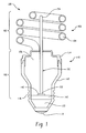
- an LED-integrated compact fluorescent lamp assembly includes a low pressure fluorescent discharge lamp 102, which has at least one low pressure discharge tube 104 is shown in FIGURE 1 .
- the CFL assembly has a helical discharge tube which has first and second end portions 106 (only one of which is shown).
- the discharge tube radiates white light by bringing a gas fill to a discharge state via an arc between electrodes, one end of each electrode extending at least partially inward into the discharge tube from each end portion 106.
- a phosphor is provided on the inner surface of the discharge tube to convert the discharge radiation into visible light.
- the end portions 106 extend into a lamp base 110 that includes a shell 112 closed off at an upper end by collar 114 and at the lower end includes an Edison type threaded portion 116 for threaded engagement with an associated socket (not shown).
- the threaded base is a conductive metal that forms one contact with the associated lamp fitting and a central metal eyelet 118 that forms the second contact.
- the shell 116 and eyelet 118 are separated by an insulating material 120.
- Lamp electronics such as a ballast (not shown) are preferably located within the shell of the embodiment of FIGURE 1 .
- the ballast supplies the necessary power electronics and circuit conditions such as voltage, current, and wave form to drive or power the compact fluorescent tubes.
- the ballast may be formed separately and not incorporated into the lamp base, although the integral ballast is preferred.
- Heat sensitive electronic components of the ballast may also require a heat reflector or shield to protect these components from the heat generated by the discharge lamp.
- At least one light emitting diode light source 140 is mounted to a heat sink or support 142 at a location in the base that maximizes the distance from the discharge tube.
- the support 142 is formed of a heat conducting material, such as metal, in order to efficiently and effectively transfer heat away from the LED light source.
- the LED is preferably a red light emitting LED for mixing with the white light emitted by the discharge lamp.
- a light guide 150 has a first or proximal end 152 adjacent the LED 140 and support 142, and a second or distal end 154 that preferably terminates adjacent the discharge tube.
- the light guide has a first or lower region disposed within the shell that preferably does not permit the light to escape through a sidewall of the light guide.
- the light is transmitted through total internal reflection (TIR) as it passes along an axial length of the light guide portion disposed within the shell and represented by reference numeral 160.
- TIR total internal reflection
- the second or upper section 162 of the light guide permits the light to be distributed along this longitudinal extent and results in good color mixing with the white light emitted from the discharge tube.
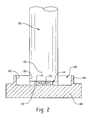
- the LED 140 is located in support 170 that preferably includes a central recess 172 so that a perimeter edge or wall 174 of the support extends axially outwardly a greater dimension than an axial dimension of the LED chip received in the central portion.
- the support is received in a heat sink 180 (which may be the same as support/heat sink 142) and that also includes a recess 182 having depth and width dimensions that easily accommodate the support 140 and fixture 190.
- Fixture 190 has an inner diameter that closely matches the outer diameter of the proximal end of 152 of the light guide and has an outer dimension 194 that closely fits within the recess 182.
- the height of the fixture 190 closely conforms to that of the recess 182 in the heat sink, and is dimensioned so that the cavity formed by inner opening 192 in the fixture accommodates the support 170 (with the LED chip therein) and also a limited axial length of the proximal end 152 of the light guide.
- the diameter of the light guide is substantially greater than that of the chip.
- the substantially planar terminal end of the light guide preferably engages an upper surface of the perimeter wall 174 of the support.
- an interior recess 172 of the support as a white surface or other similarly reflective surface, light emitted by the LED that does not proceed directly into the light guide, will be directed by the reflective surface toward the light guide and thereby enhance the coupling efficiency between the LED and the light guide.
- the limited axial receipt of the proximal end 152 of the light guide within the fixture 190 will further promote directing light emitted by the LED into the end of the light guide, i.e., enhancing optical efficiency.
- the remaining volume or cavity within recess 172 is preferably filled with air. It is also contemplated that a material, such as a gel, having a refractive index that closely matches that of the light guide could be used to fill the remainder of the recess.
- Power supply lead wires 200, 202 are shown in FIGURE 3 prior to insertion of the fixture 190 into the assembly. As evidenced in FIGURE 4 , openings 204, 206 are provided through the fixture to accommodate the power supply wires. In this manner, the light guide extends from a central portion of the fixture and the power supply wires are located at a spaced location from the light guide.
- FIGURES 2-4 The coupling arrangement of FIGURES 2-4 is desirable because of the reduced cost, and ease of manufacture and assembly.
- the white or reflective surface of the support 170 along with the relative dimensioning between the planar end of the light guide over the perimeter wall 174 of the support provides good coupling efficiency on the order of 80%.
- the enlarged mass or volume of the heat sink 180 also contributes to maintaining the operating temperature of the red LED at a reduced level.
- FIGURES 5 and 6 illustrate an alternative exemplary embodiment.
- the LED 140 is of the type that includes integrated optics; namely, an epoxy dome or lens 210, received over the LED that is mounted on substrate 212.
- the substantially planar or proximal end 152 of the light guide is interconnected with the LED assembly with a coupler 220.
- the coupler preferably has an inner reflective surface 222 that is in the shape or conformation of a paraboloid or aspheroid in which a narrow first end 224 of the reflector surface abuts along an interface between the outer perimeter 210 of the dome and an upper surface of substrate 212.
- the reflective surface then gradually widens along the parabolic or aspheric curve to second end 226 that has a stepped configuration dimensioned to receive a limited axial extent of the proximal end of the light guide.
- the coupler 220 is preferably formed of a metal or alternative materials may be used as long as the inner reflector surface 222 is such as to direct the light from the LED into the proximal end of the light guide.
- the preferred reflector surface conformations are such that the light rays are directed toward a more collimated arrangement so that total internal reflection (TIR) through the extended length of the light guide results in a higher coupling efficiency between the LED and the light guide.
- TIR total internal reflection
- the light ray trace is exhibited in FIGURE 6 where light rays exiting the dome portion 210 of the LED assembly that contact the coupler are then directed at angles contributing toward total internal reflection.
- the volume or cavity within the coupler and disposed between the dome of the LED assembly and the proximal end of the light guide is preferably air.
- the cavity could be filled with a material that has an index of refraction that closely matches the refractive index of the light guide.
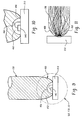
- FIGURES 7 and 8 illustrate an LED assembly that does not include the integrated optics of the type shown in FIGURE 5 .
- the bare LED chip 140 is shown on substrate 212 and coupler 320 is slightly modified in its dimensions but still serves to enhance the coupling efficiency between the LED and the light guide.
- an inner reflector surface 322 has a first or narrow end portion 324 that is dimensioned to be closely received around the bare chip 140 of the LED, and terminates or abuts against an upper surface of substrate 212.
- the inner reflector surface preferably has a paraboloid or aspheroid conformation in this embodiment so that light emitted from the LED assembly adjacent to end 324 of the reflecting surface is directed toward the wider, stepped end 326 that receives a limited axial portion of the proximal end of the light guide.
- the light ray trace shown in FIGURE 8 illustrates the advantages provided by the coupler 320 to enhance total internal reflection and encourage the light rays emitted from the LED assembly to enter into the light guide.
- FIGURES 9-11 A slightly different embodiment is shown in FIGURES 9-11 .
- a bare LED chip 140 is shown on substrate 212.
- a coupler is integrated into an end of the light guide 150.
- end 450 of the light guide has an inner reflective surface 452 also preferably of a paraboloid or aspheroid conformation.
- the reflecting surface 452 extends from first end 454 to a second end 456 where the surface transitions into an outer diameter of a remainder of the light guide.
- the terminal end of the light guide has a hemispherical or dome shaped recess 460 that is dimensioned to accommodate the bare chip 140 that is located on a surface or top of substrate 212 of the LED assembly.
- the recess 460 terminates on the end of the light guide where the reflector surface 452 begins.
- the reflector surface is brought into engagement with an upper surface of the substrate and circumferentially surrounds the LED to redirect light that extends out from 0-180 degrees from the LED chip and improve the coupling efficiency into the interior of the light guide.
- FIG. 11 A cavity 462 surrounding the LED chip assembly 140 has an air gap or a material such as a gel with a refractive index that closely matches the refractive index of the light guide.
- a paraboloid or aspheroid mirrored surface is capable of substantially collimating the rays leaving the LED source in practically any direction. Further, filling the cavity about the LED with a transparent material that has a refractive index that closely matches that of the light guide has two advantages. First, the transparent material reduces the Fresnel reflections on the LED-to-air and the air-to-light guide interfaces. Second, the transparent material also makes possible the application of total internal reflection on the reflecting surface.
- a well collimated beam of light is achieved if the exit aperture is considerably larger than the source diameter or if a length of the paraboloid allows multiple reflections.
- the desired effect of higher saturated red color rendering is achieved in the combination CFL while having the same energy consumption.
- the energy consumption of an LED can be lowered by keeping the same effect, and likewise increasing the efficiency of the combination lamp.
- a red LED consumes electrical power from 0.1 watts to 10 watts, and radiates 6-900 lumens of red light to a light guide having a diameter that ranges between 2 millimeters and 20 millimeters with an elongated shape.
- the preferred material of the light guide is a polymer or a glass, having a refractive index of 1.4 to 1.6 that effectively transfers light from the base of a CFL to the region of the discharge tube. Minimal loss of light is encountered in the region of the light guide below the plastic collar, i.e. within the shell of the base, and a maximum out-coupling is still required in the region of the discharge tubes.
- Present embodiments address the coupling-in efficiency for different types of LEDs, i.e. those equipped or not equipped with a primary or integrated optics or lens.
Landscapes
- Physics & Mathematics (AREA)
- Optics & Photonics (AREA)
- General Physics & Mathematics (AREA)
- Engineering & Computer Science (AREA)
- Microelectronics & Electronic Packaging (AREA)
- General Engineering & Computer Science (AREA)
- Non-Portable Lighting Devices Or Systems Thereof (AREA)
- Led Device Packages (AREA)
- Optical Couplings Of Light Guides (AREA)
- Planar Illumination Modules (AREA)
Applications Claiming Priority (1)
| Application Number | Priority Date | Filing Date | Title |
|---|---|---|---|
| US12/549,530 US8066417B2 (en) | 2009-08-28 | 2009-08-28 | Light emitting diode-light guide coupling apparatus |
Publications (2)
| Publication Number | Publication Date |
|---|---|
| EP2296025A2 true EP2296025A2 (de) | 2011-03-16 |
| EP2296025A3 EP2296025A3 (de) | 2011-09-21 |
Family
ID=43515220
Family Applications (1)
| Application Number | Title | Priority Date | Filing Date |
|---|---|---|---|
| EP10173275A Withdrawn EP2296025A3 (de) | 2009-08-28 | 2010-08-18 | Vorrichtung zur Kopplung zwischen einer lichtemittierenden Diode und einem Lichtleiter |
Country Status (5)
| Country | Link |
|---|---|
| US (1) | US8066417B2 (de) |
| EP (1) | EP2296025A3 (de) |
| JP (1) | JP5739629B2 (de) |
| KR (2) | KR20110023787A (de) |
| CN (1) | CN102003680B (de) |
Cited By (9)
| Publication number | Priority date | Publication date | Assignee | Title |
|---|---|---|---|---|
| WO2015104608A1 (en) * | 2014-01-08 | 2015-07-16 | Koninklijke Philips N.V. | Color mixing output for high brightness led sources |
| US9734365B2 (en) | 2012-09-10 | 2017-08-15 | Avery Dennison Retail Information Services, Llc | Method for preventing unauthorized diversion of NFC tags |
| US9767329B2 (en) | 2012-11-19 | 2017-09-19 | Avery Dennison Retail Information Services, Llc | NFC tags with proximity detection |
| US9810393B2 (en) | 2015-08-31 | 2017-11-07 | Varroc Lighting Systems, s.r.o. | Motor vehicle light device including light guide and flat electroluminsscence diode |
| US9858583B2 (en) | 2011-09-01 | 2018-01-02 | Avery Dennison Retail Information Services, Llc | Apparatus, system and method for tracking consumer product interest using mobile devices |
| US9892398B2 (en) | 2011-11-02 | 2018-02-13 | Avery Dennison Retail Information Services, Llc | Distributed point of sale, electronic article surveillance, and product information system, apparatus and method |
| US10540527B2 (en) | 2012-10-18 | 2020-01-21 | Avery Dennison Retail Information Services Llc | Method, system and apparatus for NFC security |
| US10977969B2 (en) | 2010-01-29 | 2021-04-13 | Avery Dennison Retail Information Services, Llc | RFID/NFC panel and/or array used in smart signage applications and method of using |
| US10977965B2 (en) | 2010-01-29 | 2021-04-13 | Avery Dennison Retail Information Services, Llc | Smart sign box using electronic interactions |
Families Citing this family (24)
| Publication number | Priority date | Publication date | Assignee | Title |
|---|---|---|---|---|
| JP4569683B2 (ja) | 2007-10-16 | 2010-10-27 | 東芝ライテック株式会社 | 発光素子ランプ及び照明器具 |
| JP5333758B2 (ja) * | 2009-02-27 | 2013-11-06 | 東芝ライテック株式会社 | 照明装置および照明器具 |
| US8888327B1 (en) * | 2009-06-17 | 2014-11-18 | Hubbell Incorporated | Halogen lampholder and halogen lampholder with heat shield |
| JP5348410B2 (ja) | 2009-06-30 | 2013-11-20 | 東芝ライテック株式会社 | 口金付ランプおよび照明器具 |
| JP2011049527A (ja) | 2009-07-29 | 2011-03-10 | Toshiba Lighting & Technology Corp | Led照明装置 |
| JP2011071242A (ja) * | 2009-09-24 | 2011-04-07 | Toshiba Lighting & Technology Corp | 発光装置及び照明装置 |
| JP2011091033A (ja) | 2009-09-25 | 2011-05-06 | Toshiba Lighting & Technology Corp | 発光モジュール、電球形ランプおよび照明器具 |
| US8678618B2 (en) | 2009-09-25 | 2014-03-25 | Toshiba Lighting & Technology Corporation | Self-ballasted lamp having a light-transmissive member in contact with light emitting elements and lighting equipment incorporating the same |
| US8324789B2 (en) * | 2009-09-25 | 2012-12-04 | Toshiba Lighting & Technology Corporation | Self-ballasted lamp and lighting equipment |
| CN102032481B (zh) * | 2009-09-25 | 2014-01-08 | 东芝照明技术株式会社 | 附带灯口的照明灯及照明器具 |
| JP5257622B2 (ja) | 2010-02-26 | 2013-08-07 | 東芝ライテック株式会社 | 電球形ランプおよび照明器具 |
| US8742655B2 (en) * | 2011-07-22 | 2014-06-03 | Guardian Industries Corp. | LED lighting systems with phosphor subassemblies, and/or methods of making the same |
| TW201309971A (zh) * | 2011-08-19 | 2013-03-01 | Wintek Corp | 照明裝置 |
| JP6250541B2 (ja) * | 2011-08-19 | 2017-12-20 | フィリップス ライティング ホールディング ビー ヴィ | キャンドルライトled電球 |
| WO2013097156A1 (zh) * | 2011-12-29 | 2013-07-04 | 胡斌 | 一种led导光透镜 |
| TWM439153U (en) * | 2011-12-29 | 2012-10-11 | Xu Xiu Yu | Lamp structure with switchable illumination modes |
| CN102798083A (zh) * | 2012-08-24 | 2012-11-28 | 四川省电力公司西昌电业局 | 一种导光装置 |
| US9097396B2 (en) * | 2012-09-04 | 2015-08-04 | Cree, Inc. | LED based lighting system |
| TWI578043B (zh) * | 2012-10-24 | 2017-04-11 | 鴻海精密工業股份有限公司 | 光電轉換模組 |
| CN103383078A (zh) * | 2013-07-08 | 2013-11-06 | 李忠凯 | 一种led灯具 |
| FR3023526B1 (fr) | 2014-07-10 | 2017-12-29 | Renault Sas | Procede de selection de la consigne d'etat d'une chaine cinematique |
| JP7236659B2 (ja) * | 2019-01-18 | 2023-03-10 | パナソニックIpマネジメント株式会社 | 照明装置及び照明装置の製造方法 |
| JP2022020174A (ja) * | 2020-07-20 | 2022-02-01 | コイト電工株式会社 | 照明装置 |
| CN113339747A (zh) * | 2021-07-08 | 2021-09-03 | 华域视觉科技(上海)有限公司 | 一种光导结构、车灯、车辆及其制造方法 |
Citations (6)
| Publication number | Priority date | Publication date | Assignee | Title |
|---|---|---|---|---|
| US5732176A (en) | 1993-06-29 | 1998-03-24 | Savage, Jr.; John M. | Light pipe optical coupling between LED and fiber optics cable |
| JP2005136349A (ja) * | 2003-10-31 | 2005-05-26 | Toyoda Gosei Co Ltd | 発光装置及びその反射ミラー |
| WO2005094378A2 (en) * | 2004-03-30 | 2005-10-13 | Illumination Management Solutions, Inc. | An apparatus and method for improved illumination area fill |
| US7279345B2 (en) | 2000-09-12 | 2007-10-09 | Philips Lumileds Lighting Company, Llc | Method of forming light emitting devices with improved light extraction efficiency |
| JP2008135210A (ja) * | 2006-11-27 | 2008-06-12 | Toshiba Lighting & Technology Corp | Led電球および照明器具 |
| US7543957B1 (en) | 2008-01-29 | 2009-06-09 | General Electric Company | Thermal management of LEDS integrated to compact fluorescent lamps |
Family Cites Families (23)
| Publication number | Priority date | Publication date | Assignee | Title |
|---|---|---|---|---|
| JPS5669607A (en) * | 1979-11-09 | 1981-06-11 | Mitsubishi Electric Corp | Photocoupler |
| US4767172A (en) | 1983-01-28 | 1988-08-30 | Xerox Corporation | Collector for an LED array |
| JPH02135307A (ja) * | 1988-11-16 | 1990-05-24 | Iwasaki Electric Co Ltd | 光伝送リンク |
| JP4325049B2 (ja) * | 1999-11-25 | 2009-09-02 | パナソニック電工株式会社 | ライトガイド型照明装置 |
| JP2002094129A (ja) * | 1999-11-30 | 2002-03-29 | Omron Corp | 光学装置及び当該光学装置を用いた機器 |
| JP3725406B2 (ja) * | 2000-07-21 | 2005-12-14 | サンクス株式会社 | 光結合装置 |
| US6526201B1 (en) * | 2000-10-12 | 2003-02-25 | Delphi Technologies, Inc. | Light transport coupler assembly |
| DE10065624C2 (de) * | 2000-12-29 | 2002-11-14 | Hans Kragl | Kopplungsanordnung zum optischen Koppeln eines Lichtwellenleiters mit einem elektro-optischen oder opto-elektrischen Halbleiterwandler |
| US6560038B1 (en) * | 2001-12-10 | 2003-05-06 | Teledyne Lighting And Display Products, Inc. | Light extraction from LEDs with light pipes |
| JP3996164B2 (ja) * | 2002-05-17 | 2007-10-24 | シーシーエス株式会社 | 発光ダイオード装置及び発光ダイオード装置の製造方法 |
| DE10250383B4 (de) * | 2002-10-29 | 2007-05-10 | Diemount Gmbh | Leuchtdiodenanordnung mit Reflektor |
| EP1567894A2 (de) * | 2002-12-02 | 2005-08-31 | 3M Innovative Properties Company | Beleuchtungssystem das eine mehrzahl von lichtquellen benutzt |
| DE10257128B3 (de) * | 2002-12-05 | 2004-05-27 | Schott Glas | Vorrichtung zur Einkopplung von Licht in einen Lichtleiter |
| DE10332393A1 (de) * | 2003-07-17 | 2005-02-03 | Schefenacker Vision Systems Germany Gmbh & Co. Kg | Leuchte für Fahrzeuge, vorzugsweise Kraftfahrzeuge |
| US7009213B2 (en) | 2003-07-31 | 2006-03-07 | Lumileds Lighting U.S., Llc | Light emitting devices with improved light extraction efficiency |
| JP2005136224A (ja) * | 2003-10-30 | 2005-05-26 | Asahi Kasei Electronics Co Ltd | 発光ダイオード照明モジュール |
| US20050116635A1 (en) * | 2003-12-02 | 2005-06-02 | Walson James E. | Multiple LED source and method for assembling same |
| FI117492B (fi) * | 2004-10-26 | 2006-10-31 | Jukka Vanhala | Valoa emittoiva laite ja menetelmä valon suuntaamiseksi |
| WO2006102846A1 (en) * | 2005-04-01 | 2006-10-05 | Yi Li | High efficient light coupling of solid-state light source into etendue maintained optical waveguide/fiber |
| CA2617314A1 (en) * | 2005-04-05 | 2006-10-12 | Tir Technology Lp | Mounting assembly for optoelectronic devices |
| JP2007265688A (ja) * | 2006-03-27 | 2007-10-11 | Harison Toshiba Lighting Corp | コリメーションレンズ及びこれを用いた照明装置 |
| US20090079316A1 (en) * | 2007-09-21 | 2009-03-26 | General Electric Company | Outer envelope and lamp with outer envelope |
| US7759880B2 (en) * | 2008-02-12 | 2010-07-20 | General Electric Company | Combined ballast for fluorescent lamp and light emitting diode and method of driving same |
-
2009
- 2009-08-28 US US12/549,530 patent/US8066417B2/en active Active
-
2010
- 2010-08-18 EP EP10173275A patent/EP2296025A3/de not_active Withdrawn
- 2010-08-26 JP JP2010188947A patent/JP5739629B2/ja active Active
- 2010-08-26 KR KR1020100082957A patent/KR20110023787A/ko not_active Ceased
- 2010-08-27 CN CN201010272829.9A patent/CN102003680B/zh active Active
-
2018
- 2018-07-18 KR KR1020180083632A patent/KR102025016B1/ko active Active
Patent Citations (6)
| Publication number | Priority date | Publication date | Assignee | Title |
|---|---|---|---|---|
| US5732176A (en) | 1993-06-29 | 1998-03-24 | Savage, Jr.; John M. | Light pipe optical coupling between LED and fiber optics cable |
| US7279345B2 (en) | 2000-09-12 | 2007-10-09 | Philips Lumileds Lighting Company, Llc | Method of forming light emitting devices with improved light extraction efficiency |
| JP2005136349A (ja) * | 2003-10-31 | 2005-05-26 | Toyoda Gosei Co Ltd | 発光装置及びその反射ミラー |
| WO2005094378A2 (en) * | 2004-03-30 | 2005-10-13 | Illumination Management Solutions, Inc. | An apparatus and method for improved illumination area fill |
| JP2008135210A (ja) * | 2006-11-27 | 2008-06-12 | Toshiba Lighting & Technology Corp | Led電球および照明器具 |
| US7543957B1 (en) | 2008-01-29 | 2009-06-09 | General Electric Company | Thermal management of LEDS integrated to compact fluorescent lamps |
Cited By (15)
| Publication number | Priority date | Publication date | Assignee | Title |
|---|---|---|---|---|
| US10977969B2 (en) | 2010-01-29 | 2021-04-13 | Avery Dennison Retail Information Services, Llc | RFID/NFC panel and/or array used in smart signage applications and method of using |
| US10977965B2 (en) | 2010-01-29 | 2021-04-13 | Avery Dennison Retail Information Services, Llc | Smart sign box using electronic interactions |
| US9858583B2 (en) | 2011-09-01 | 2018-01-02 | Avery Dennison Retail Information Services, Llc | Apparatus, system and method for tracking consumer product interest using mobile devices |
| US10607238B2 (en) | 2011-09-01 | 2020-03-31 | Avery Dennison Corporation | Apparatus, system and method for consumer tracking consumer product interest using mobile devices |
| US9892398B2 (en) | 2011-11-02 | 2018-02-13 | Avery Dennison Retail Information Services, Llc | Distributed point of sale, electronic article surveillance, and product information system, apparatus and method |
| US9734365B2 (en) | 2012-09-10 | 2017-08-15 | Avery Dennison Retail Information Services, Llc | Method for preventing unauthorized diversion of NFC tags |
| US10282572B2 (en) | 2012-09-10 | 2019-05-07 | Avery Dennison Retail Information Services, Llc | Method for preventing unauthorized diversion of NFC tags |
| US11126803B2 (en) | 2012-10-18 | 2021-09-21 | Avery Dennison Corporation | Method, system and apparatus for NFC security |
| US10540527B2 (en) | 2012-10-18 | 2020-01-21 | Avery Dennison Retail Information Services Llc | Method, system and apparatus for NFC security |
| US9767329B2 (en) | 2012-11-19 | 2017-09-19 | Avery Dennison Retail Information Services, Llc | NFC tags with proximity detection |
| US10402598B2 (en) | 2012-11-19 | 2019-09-03 | Avery Dennison Retail Information Services, Llc | NFC tags with proximity detection |
| US10970496B2 (en) | 2012-11-19 | 2021-04-06 | Avery Dennison Retail Information Services, Llc | NFC tags with proximity detection |
| US9976707B2 (en) | 2014-01-08 | 2018-05-22 | Philips Lighting Holding B.V. | Color mixing output for high brightness LED sources |
| WO2015104608A1 (en) * | 2014-01-08 | 2015-07-16 | Koninklijke Philips N.V. | Color mixing output for high brightness led sources |
| US9810393B2 (en) | 2015-08-31 | 2017-11-07 | Varroc Lighting Systems, s.r.o. | Motor vehicle light device including light guide and flat electroluminsscence diode |
Also Published As
| Publication number | Publication date |
|---|---|
| JP5739629B2 (ja) | 2015-06-24 |
| CN102003680A (zh) | 2011-04-06 |
| JP2011048371A (ja) | 2011-03-10 |
| US8066417B2 (en) | 2011-11-29 |
| KR20180085380A (ko) | 2018-07-26 |
| US20110051424A1 (en) | 2011-03-03 |
| KR102025016B1 (ko) | 2019-09-24 |
| KR20110023787A (ko) | 2011-03-08 |
| EP2296025A3 (de) | 2011-09-21 |
| CN102003680B (zh) | 2015-11-25 |
Similar Documents
| Publication | Publication Date | Title |
|---|---|---|
| US8066417B2 (en) | Light emitting diode-light guide coupling apparatus | |
| CN101933398B (zh) | 集成到紧凑型荧光灯中的led的热学管理 | |
| US8702292B2 (en) | Linear illumination devices having light guides and LED-based illumination modules | |
| CN100373638C (zh) | 发光二极管及其发光二极管灯 | |
| CA2490930C (en) | Led lamp with central optical light guide | |
| US8330342B2 (en) | Spherical light output LED lens and heat sink stem system | |
| US20130039072A1 (en) | Lighting device | |
| JP6321998B2 (ja) | 照明装置 | |
| JP2010198807A (ja) | 照明装置 | |
| WO2013086694A1 (en) | Side-emitting guidepipe technology on led lamp to make filament effect | |
| KR20020084089A (ko) | 형광 램프를 사용한 조명 장치 | |
| CN213452929U (zh) | 一种照明装置及一种灯具 | |
| KR102014173B1 (ko) | 조명 장치 | |
| CN101305445B (zh) | 紧凑型荧光灯 | |
| KR101160842B1 (ko) | 고출력 엘이디 패키지 모듈 | |
| KR101039653B1 (ko) | 조명 장치 | |
| KR102014174B1 (ko) | 조명 장치 | |
| KR101078540B1 (ko) | 고방사효율을 가지는 발광다이오드조명기기 | |
| KR101171811B1 (ko) | 조명 장치 | |
| KR20070032326A (ko) | 고 전력 발광 다이오드 전자 광학 조립체 | |
| CN107781711A (zh) | Led散热筒灯 | |
| KR20140120636A (ko) | 조명 장치 | |
| KR20140120634A (ko) | 조명 장치 | |
| KR20140120633A (ko) | 조명 장치 | |
| KR20140135348A (ko) | 조명 장치 |
Legal Events
| Date | Code | Title | Description |
|---|---|---|---|
| PUAI | Public reference made under article 153(3) epc to a published international application that has entered the european phase |
Free format text: ORIGINAL CODE: 0009012 |
|
| AK | Designated contracting states |
Kind code of ref document: A2 Designated state(s): AL AT BE BG CH CY CZ DE DK EE ES FI FR GB GR HR HU IE IS IT LI LT LU LV MC MK MT NL NO PL PT RO SE SI SK SM TR |
|
| AX | Request for extension of the european patent |
Extension state: BA ME RS |
|
| PUAL | Search report despatched |
Free format text: ORIGINAL CODE: 0009013 |
|
| AK | Designated contracting states |
Kind code of ref document: A3 Designated state(s): AL AT BE BG CH CY CZ DE DK EE ES FI FR GB GR HR HU IE IS IT LI LT LU LV MC MK MT NL NO PL PT RO SE SI SK SM TR |
|
| AX | Request for extension of the european patent |
Extension state: BA ME RS |
|
| RIC1 | Information provided on ipc code assigned before grant |
Ipc: G02B 6/42 20060101AFI20110812BHEP Ipc: F21V 8/00 20060101ALN20110812BHEP Ipc: G02B 6/00 20060101ALI20110812BHEP Ipc: H05B 35/00 20060101ALN20110812BHEP Ipc: H01L 33/60 20100101ALN20110812BHEP |
|
| 17P | Request for examination filed |
Effective date: 20120321 |
|
| STAA | Information on the status of an ep patent application or granted ep patent |
Free format text: STATUS: EXAMINATION IS IN PROGRESS |
|
| 17Q | First examination report despatched |
Effective date: 20180227 |
|
| RIC1 | Information provided on ipc code assigned before grant |
Ipc: G02B 6/42 20060101AFI20200825BHEP Ipc: F21V 8/00 20060101ALN20200825BHEP Ipc: H01L 33/58 20100101ALN20200825BHEP Ipc: H05B 35/00 20060101ALN20200825BHEP Ipc: G02B 6/00 20060101ALI20200825BHEP |
|
| RIC1 | Information provided on ipc code assigned before grant |
Ipc: G02B 6/00 20060101ALI20200904BHEP Ipc: F21V 8/00 20060101ALN20200904BHEP Ipc: H01L 33/58 20100101ALN20200904BHEP Ipc: G02B 6/42 20060101AFI20200904BHEP Ipc: H05B 35/00 20060101ALN20200904BHEP |
|
| GRAP | Despatch of communication of intention to grant a patent |
Free format text: ORIGINAL CODE: EPIDOSNIGR1 |
|
| STAA | Information on the status of an ep patent application or granted ep patent |
Free format text: STATUS: GRANT OF PATENT IS INTENDED |
|
| RIC1 | Information provided on ipc code assigned before grant |
Ipc: G02B 6/42 20060101AFI20200930BHEP Ipc: F21V 8/00 20060101ALN20200930BHEP Ipc: H05B 35/00 20060101ALN20200930BHEP Ipc: H01L 33/58 20100101ALN20200930BHEP Ipc: G02B 6/00 20060101ALI20200930BHEP |
|
| INTG | Intention to grant announced |
Effective date: 20201019 |
|
| STAA | Information on the status of an ep patent application or granted ep patent |
Free format text: STATUS: THE APPLICATION IS DEEMED TO BE WITHDRAWN |
|
| 18D | Application deemed to be withdrawn |
Effective date: 20210302 |