EP2296231A1 - Connecteur coaxial par moulage multi-injections et procédé de fabrication - Google Patents
Connecteur coaxial par moulage multi-injections et procédé de fabrication Download PDFInfo
- Publication number
- EP2296231A1 EP2296231A1 EP10008225A EP10008225A EP2296231A1 EP 2296231 A1 EP2296231 A1 EP 2296231A1 EP 10008225 A EP10008225 A EP 10008225A EP 10008225 A EP10008225 A EP 10008225A EP 2296231 A1 EP2296231 A1 EP 2296231A1
- Authority
- EP
- European Patent Office
- Prior art keywords
- connector
- inner body
- cable connector
- injection
- molded
- Prior art date
- Legal status (The legal status is an assumption and is not a legal conclusion. Google has not performed a legal analysis and makes no representation as to the accuracy of the status listed.)
- Withdrawn
Links
Images








Classifications
-
- H—ELECTRICITY
- H01—ELECTRIC ELEMENTS
- H01R—ELECTRICALLY-CONDUCTIVE CONNECTIONS; STRUCTURAL ASSOCIATIONS OF A PLURALITY OF MUTUALLY-INSULATED ELECTRICAL CONNECTING ELEMENTS; COUPLING DEVICES; CURRENT COLLECTORS
- H01R9/00—Structural associations of a plurality of mutually-insulated electrical connecting elements, e.g. terminal strips or terminal blocks; Terminals or binding posts mounted upon a base or in a case; Bases therefor
- H01R9/03—Connectors arranged to contact a plurality of the conductors of a multiconductor cable, e.g. tapping connections
- H01R9/05—Connectors arranged to contact a plurality of the conductors of a multiconductor cable, e.g. tapping connections for coaxial cables
- H01R9/0521—Connection to outer conductor by action of a nut
-
- B—PERFORMING OPERATIONS; TRANSPORTING
- B29—WORKING OF PLASTICS; WORKING OF SUBSTANCES IN A PLASTIC STATE IN GENERAL
- B29C—SHAPING OR JOINING OF PLASTICS; SHAPING OF MATERIAL IN A PLASTIC STATE, NOT OTHERWISE PROVIDED FOR; AFTER-TREATMENT OF THE SHAPED PRODUCTS, e.g. REPAIRING
- B29C45/00—Injection moulding, i.e. forcing the required volume of moulding material through a nozzle into a closed mould; Apparatus therefor
- B29C45/14—Injection moulding, i.e. forcing the required volume of moulding material through a nozzle into a closed mould; Apparatus therefor incorporating preformed parts or layers, e.g. injection moulding around inserts or for coating articles
- B29C45/14639—Injection moulding, i.e. forcing the required volume of moulding material through a nozzle into a closed mould; Apparatus therefor incorporating preformed parts or layers, e.g. injection moulding around inserts or for coating articles for obtaining an insulating effect, e.g. for electrical components
-
- B—PERFORMING OPERATIONS; TRANSPORTING
- B29—WORKING OF PLASTICS; WORKING OF SUBSTANCES IN A PLASTIC STATE IN GENERAL
- B29C—SHAPING OR JOINING OF PLASTICS; SHAPING OF MATERIAL IN A PLASTIC STATE, NOT OTHERWISE PROVIDED FOR; AFTER-TREATMENT OF THE SHAPED PRODUCTS, e.g. REPAIRING
- B29C45/00—Injection moulding, i.e. forcing the required volume of moulding material through a nozzle into a closed mould; Apparatus therefor
- B29C45/16—Making multilayered or multicoloured articles
-
- H—ELECTRICITY
- H01—ELECTRIC ELEMENTS
- H01R—ELECTRICALLY-CONDUCTIVE CONNECTIONS; STRUCTURAL ASSOCIATIONS OF A PLURALITY OF MUTUALLY-INSULATED ELECTRICAL CONNECTING ELEMENTS; COUPLING DEVICES; CURRENT COLLECTORS
- H01R13/00—Details of coupling devices of the kinds covered by groups H01R12/70 or H01R24/00 - H01R33/00
- H01R13/40—Securing contact members in or to a base or case; Insulating of contact members
- H01R13/405—Securing in non-demountable manner, e.g. moulding, riveting
-
- H—ELECTRICITY
- H01—ELECTRIC ELEMENTS
- H01R—ELECTRICALLY-CONDUCTIVE CONNECTIONS; STRUCTURAL ASSOCIATIONS OF A PLURALITY OF MUTUALLY-INSULATED ELECTRICAL CONNECTING ELEMENTS; COUPLING DEVICES; CURRENT COLLECTORS
- H01R13/00—Details of coupling devices of the kinds covered by groups H01R12/70 or H01R24/00 - H01R33/00
- H01R13/46—Bases; Cases
- H01R13/502—Bases; Cases composed of different pieces
- H01R13/504—Bases; Cases composed of different pieces different pieces being moulded, cemented, welded, e.g. ultrasonic welding, or swaged together
-
- H—ELECTRICITY
- H01—ELECTRIC ELEMENTS
- H01R—ELECTRICALLY-CONDUCTIVE CONNECTIONS; STRUCTURAL ASSOCIATIONS OF A PLURALITY OF MUTUALLY-INSULATED ELECTRICAL CONNECTING ELEMENTS; COUPLING DEVICES; CURRENT COLLECTORS
- H01R13/00—Details of coupling devices of the kinds covered by groups H01R12/70 or H01R24/00 - H01R33/00
- H01R13/46—Bases; Cases
- H01R13/502—Bases; Cases composed of different pieces
- H01R13/512—Bases; Cases composed of different pieces assembled by screw or screws
-
- H—ELECTRICITY
- H01—ELECTRIC ELEMENTS
- H01R—ELECTRICALLY-CONDUCTIVE CONNECTIONS; STRUCTURAL ASSOCIATIONS OF A PLURALITY OF MUTUALLY-INSULATED ELECTRICAL CONNECTING ELEMENTS; COUPLING DEVICES; CURRENT COLLECTORS
- H01R43/00—Apparatus or processes specially adapted for manufacturing, assembling, maintaining, or repairing of line connectors or current collectors or for joining electric conductors
- H01R43/18—Apparatus or processes specially adapted for manufacturing, assembling, maintaining, or repairing of line connectors or current collectors or for joining electric conductors for manufacturing bases or cases for contact members
-
- H—ELECTRICITY
- H01—ELECTRIC ELEMENTS
- H01R—ELECTRICALLY-CONDUCTIVE CONNECTIONS; STRUCTURAL ASSOCIATIONS OF A PLURALITY OF MUTUALLY-INSULATED ELECTRICAL CONNECTING ELEMENTS; COUPLING DEVICES; CURRENT COLLECTORS
- H01R43/00—Apparatus or processes specially adapted for manufacturing, assembling, maintaining, or repairing of line connectors or current collectors or for joining electric conductors
- H01R43/20—Apparatus or processes specially adapted for manufacturing, assembling, maintaining, or repairing of line connectors or current collectors or for joining electric conductors for assembling or disassembling contact members with insulating base, case or sleeve
- H01R43/24—Assembling by moulding on contact members
-
- B—PERFORMING OPERATIONS; TRANSPORTING
- B29—WORKING OF PLASTICS; WORKING OF SUBSTANCES IN A PLASTIC STATE IN GENERAL
- B29C—SHAPING OR JOINING OF PLASTICS; SHAPING OF MATERIAL IN A PLASTIC STATE, NOT OTHERWISE PROVIDED FOR; AFTER-TREATMENT OF THE SHAPED PRODUCTS, e.g. REPAIRING
- B29C45/00—Injection moulding, i.e. forcing the required volume of moulding material through a nozzle into a closed mould; Apparatus therefor
- B29C45/16—Making multilayered or multicoloured articles
- B29C2045/1696—Making multilayered or multicoloured articles injecting metallic layers and plastic material layers
-
- H—ELECTRICITY
- H01—ELECTRIC ELEMENTS
- H01R—ELECTRICALLY-CONDUCTIVE CONNECTIONS; STRUCTURAL ASSOCIATIONS OF A PLURALITY OF MUTUALLY-INSULATED ELECTRICAL CONNECTING ELEMENTS; COUPLING DEVICES; CURRENT COLLECTORS
- H01R13/00—Details of coupling devices of the kinds covered by groups H01R12/70 or H01R24/00 - H01R33/00
- H01R13/46—Bases; Cases
- H01R13/52—Dustproof, splashproof, drip-proof, waterproof, or flameproof cases
- H01R13/5205—Sealing means between cable and housing, e.g. grommet
-
- H—ELECTRICITY
- H01—ELECTRIC ELEMENTS
- H01R—ELECTRICALLY-CONDUCTIVE CONNECTIONS; STRUCTURAL ASSOCIATIONS OF A PLURALITY OF MUTUALLY-INSULATED ELECTRICAL CONNECTING ELEMENTS; COUPLING DEVICES; CURRENT COLLECTORS
- H01R13/00—Details of coupling devices of the kinds covered by groups H01R12/70 or H01R24/00 - H01R33/00
- H01R13/46—Bases; Cases
- H01R13/52—Dustproof, splashproof, drip-proof, waterproof, or flameproof cases
- H01R13/5219—Sealing means between coupling parts, e.g. interfacial seal
-
- H—ELECTRICITY
- H01—ELECTRIC ELEMENTS
- H01R—ELECTRICALLY-CONDUCTIVE CONNECTIONS; STRUCTURAL ASSOCIATIONS OF A PLURALITY OF MUTUALLY-INSULATED ELECTRICAL CONNECTING ELEMENTS; COUPLING DEVICES; CURRENT COLLECTORS
- H01R13/00—Details of coupling devices of the kinds covered by groups H01R12/70 or H01R24/00 - H01R33/00
- H01R13/62—Means for facilitating engagement or disengagement of coupling parts or for holding them in engagement
- H01R13/622—Screw-ring or screw-casing
-
- H—ELECTRICITY
- H01—ELECTRIC ELEMENTS
- H01R—ELECTRICALLY-CONDUCTIVE CONNECTIONS; STRUCTURAL ASSOCIATIONS OF A PLURALITY OF MUTUALLY-INSULATED ELECTRICAL CONNECTING ELEMENTS; COUPLING DEVICES; CURRENT COLLECTORS
- H01R2103/00—Two poles
-
- H—ELECTRICITY
- H01—ELECTRIC ELEMENTS
- H01R—ELECTRICALLY-CONDUCTIVE CONNECTIONS; STRUCTURAL ASSOCIATIONS OF A PLURALITY OF MUTUALLY-INSULATED ELECTRICAL CONNECTING ELEMENTS; COUPLING DEVICES; CURRENT COLLECTORS
- H01R24/00—Two-part coupling devices, or either of their cooperating parts, characterised by their overall structure
- H01R24/38—Two-part coupling devices, or either of their cooperating parts, characterised by their overall structure having concentrically or coaxially arranged contacts
- H01R24/40—Two-part coupling devices, or either of their cooperating parts, characterised by their overall structure having concentrically or coaxially arranged contacts specially adapted for high frequency
Definitions
- the invention relates to an electrical connector. More particularly the invention relates to a lightweight and cost efficient electrical connector for coaxial cable with significant material and manufacturing efficiencies realized by application of multi-shot injection molding technology.
- Connectors for coaxial cable are typically manufactured via precision machining of a plurality of metal and dielectric elements that are then assembled to form the connector assembly.
- the inventor has recognized that injection moldable metal compositions, usable with conventional polymeric injection molding equipment, enables manufacture of multi-shot combination metal and polymeric material connector assemblies. Thereby, numerous manufacturing steps and the prior need for additional seals between separate elements may be eliminated to realize a significant materials and manufacturing cost savings.
- An example of an injection moldable metal composition is "Xyloy” TM M950 available from Cool Poly, Inc. of Warwick, RI, US.
- "Xyloy” TM M950 comprises an aluminum and zinc composition delivered in pellet form to injection molding equipment in the same manner as raw polymer pellets. Because the melting point of zinc is comparatively low, a combination of aluminum and zinc results in an alloy with a low enough melting point and viscosity characteristics suitable for use in polymeric injection molding machines without requiring any modification thereto.
- Other suitable injection moldable metal compositions preferably have melting points and viscosity characteristics that similarly enable use of conventional polymeric injection molding equipment with maximum operating temperatures around 1100 degrees Fahrenheit.
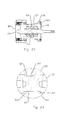
- FIG. 1-4 Exemplary embodiments of coaxial connectors configured for connection to annular corrugated solid outer conductor coaxial cable are shown in Figures 1-4 .
- Figures 1 and 2 demonstrate a connector configured for the 7-16 DIN Female standard connection interface
- Figures 3 and 4 demonstrate a connector configured for the 7-16 DIN Male standard connection interface.
- any desired standard or proprietary connection interface may be applied.
- alternative cable attachment mechanisms well known in the art, for example suitable for straight wall or helically corrugated outer conductor coaxial cable, may be applied.
- the connector is configured for use with annular corrugated outer conductor coaxial cable (not shown).
- the cable is received through a bore 1 of a coupling body 3, a slip ring 5 and the connector body 7.
- a leading edge of the outer conductor is retained clamped between an annular ramp surface 9 formed on an end face 10 of an inner body 17 of the connector body 7 and a clamp spring 11, such as a canted coil spring.
- the clamp spring 11 is pressed against the outer surface of the leading edge by the slip ring 5 driven by the coupling body 3.
- the slip ring 5 is rotatable independent of the coupling body 3, to minimize the chance for damage to the clamp spring 11 during rotation of the coupling body 3 to thread the coupling body 3 upon the connector body 7, thus applying the clamping force to the leading edge of the outer conductor.
- An inner conductor of the coaxial cable is received into an inner contact 13 held coaxial within the bore 1 by a dielectric insulator 15.
- a metal inner body 17 is provided as an outer conductor conductive path between the annular ramp surface 9 and the connection interface 19.
- a polymeric outer body 21 surrounds the inner body 17 and may include, for example, tool flats 23 for use during connector assembly and or mating threads 25 for the coupling body 3.
- the slip ring 5 spring mating surface 27 with the clamp spring 11 may be formed of metal, to avoid polymeric material creep that may occur over time which could prevent easy separation of the clamp spring 11 from the split ring 5 when removed, for example, for periodic inspections of the cable and connector interconnection.
- a cylindrical slip ring body 29 that maintains coaxial alignment of the slip ring 5 with the coaxial cable may be formed from polymeric material.
- the coupling body 3 may be formed entirely from polymeric material.
- Environmental sealing of the connector may be improved by applying environmental seal(s) 31 such as gasket(s) and/or o-rings between the outer conductor and the connector, for example positioned between the slip ring 5 and the coupling body 3 and/or between the connector body 7 and the coupling body 3.
- a further sheath seal 33, sealing between the coupling body 3 and an outer sheath of the cable may be formed in place upon an outer surface of the coupling body 3 bore 1, for example molded into an annular groove 35.
- the inner contact 13 may be similarly manufactured by molding, a conventionally machined inner contact 13 is preferred to enable use of beryllium copper and or phosphor bronze alloys with suitable mechanical characteristics for spring finger and/or spring basket 37 features of the inner contact 13 that receive and retain the inner conductor of the cable and/or of the inner conductor mating portions of the mating connector at the connection interface 19.
- multi-shot injection molding is understood to be an injection molding manufacturing procedure wherein additional layers are injection molded upon a base element and/or prior injection molded layers.
- the portion undergoing molding need not be fully released from the mold. Instead, the portion is retained aligned within the mold nest and only portions of the mold as required to define a further cavity to be injection molded with material are reconfigured.
- the resulting element is permanently integrated without any mechanical coupling mechanisms, fasteners or assembly requirements.
- a mold for the conductive sleeve is injected with the injection moldable metal composition, forming the inner body 17 conductive sleeve.
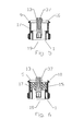
- An inner portion of the mold is removed and the inner contact 13 positioned therein as shown for example in Figure 5 .
- the inner contact 13 may be positioned first, and mold portions nested thereupon using the inner contact 13 as an alignment element for the various molding operations.
- a space between the inner contact 13 and the inner body 17 is then injected with a dielectric polymer to form the dielectric insulator 15 in situ as shown in Figure 6 .
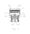
- the inner body 17 is also positioned as the core for a molding step wherein a polymer is injected to form the outer body 21 in situ as shown in Figure 7 .
- the order of molding is preferably arranged based upon the melting point of the various materials applied with the injection moldable metal composition typically being first, the dielectric polymer second and the outer body 21 polymer last.
- the slip ring mating surface 27, as shown in Figure 8 may be similarly formed by injecting the injection moldable metal composition into a slip ring mating surface mold, then, if desired, replacing a portion of the mold to form an adjacent cavity for injection of polymeric material to form the slip ring body 29 integral with the slip ring mating surface 27 as shown in Figure 9 .
- the coupling body 3, as shown in Figure 10 may be formed by injecting a polymer into a coupling body mold. If desired, the coupling body mold may be opened and portions exchanged to form a sheath seal cavity that is then injected with a polymeric gasket material to form the sheath seal 33 in situ, as shown in Figure 11 .
- the connector is formed in only three main elements that are easily assembled with the desired environmental seal(s) 31, clamp spring 11 and any further connection interface 19 portions to form the connector.
- the slip ring 5 may be eliminated by forming the coupling body 3 as a monolithic polymer portion with a clamp ring surface 39 for direct engagement with the clamp spring 11 or the like, as shown for example in Figures 12-14 .
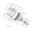
- FIG. 15 and 16 additional alternative configurations also eliminate the clamp spring 11 by forming the coupling body 3 with spring finger(s) 41.
- a representative coupling body and associated connector body 7 retaining lip 43 are disclosed in detail in US Utility Patent No. 7435135 , "Annular Corrugated Coaxial Cable Connector with Polymeric Spring Finger Nut” by Jim Wlos, issued October 14, 2008, co-owned with the present application by Andrew LLC and hereby incorporated by reference in the entirety.
- the resulting connector has only two primary elements.
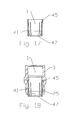
- a spring finger portion 45 may be first formed from the injection moldable metal composition as shown in Figure 17 , over which the remainder of the coupling body 3 is molded from polymer material, as shown in Figure 18 .
- Environmental seal(s) 31 for example between the coupling body 3 and the cable outer conductor and or sheath may also be added, as described herein above.
- the connector configuration may be further enhanced, for example with respect to connector layer interlocking, environmental sealing, material requirement reduction and/or tool flat 23 integrity.
- Connector layer interlocking may be applied to ensure that the various layers of the connector remain interlocked, for example as significant rotational and/or axial forces are applied during connector to cable and/or connector to connector assembly.
- further interlocking may be applied via application of interlock feature(s) 47, for example as groove(s) 49 and/or ridges on the inner contact 13 and/or the inner diameter of the inner body 17.
- the interlock feature 47 may be provided, for example, as a groove 49 of the inner body 17 that mates with a lip 51 of the dielectric insulator 15, as best shown in Figure 19 .
- the shrinkage characteristic differential between the metal and the polymer material will act upon the periphery of the groove 49 and/or lip 51, increasing the connector layer interlocking and also providing a continuous radial environmental seal between these layers.
- Further interlock feature(s) 47 may be applied as protrusion(s) 53 for improved rotational interlock. Where the protrusion(s) 53 are positioned proximate a mold break point 54, protrusion(s) 53 that would require significant additional machining in a conventional connector manufacture procedure may be easily applied.
- Connector layer interlocking between the dielectric insulator 15 and the inner contact 13 may be applied, for example, as shoulder(s) 55 between which the dielectric insulator 15 is molded for axial interlocking and as axial rib(s) 57 for rotational interlocking.
- Improved polymer thickness uniformity may reduce a required set time for the, for example, outer body 21 polymer molding step by minimizing areas of greater than average polymer thickness within the element. Thereby, polymer material requirements and the overall weight of the coaxial connector may be reduced.
- a primary area of increased material thickness in the outer body 21 is located proximate the tool flat(s) 23. By forming the tool flat(s) 23 with material reduction groove(s) 59 polymer material thickness with respect to the closest external surface may be significantly reduced.
- the relatively soft polymer material tool flat(s) 23 of a connector may be damaged by application of wrenches of incorrect size and/or inadequate precision.
- the inner body 17 may be provided with reinforcing tool flat support(s) 49 around which the tool flat(s) 23 of the outer body 21 may then be further formed during the outer body 21 molding step.
- the tool flat support(s) 56 also aid in reducing areas of increased material thickness and provide substantial connector layer interlocking as described herein above.
- material reduction groove(s) may also be applied to tool flat(s) 23 of the coupling body 23.
- Figures 22-24 demonstrate panel mount coaxial connector embodiments with interlock feature(s) 47 formed as annular protrusion(s) 53 operative as radial, axial and environmental seals.
- Figures 25-29 demonstrate discrete protrusion(s) 53 as the interlock feature(s) 47 providing a connector configuration with reduced impact upon connector pass through electrical characteristics.
- FIG. 22-29 Another feature demonstrated in the connector embodiments of Figures 22-29 is application of an outer body 21 polymer layer operative as an insulator for the panel mount connector to reduce galvanic corrosion that may occur with respect to fasteners applied to mount the connector upon the panel.
- the outer body 21 may be applied around the mounting hole(s) 61, providing a galvanic break between the mounting hole(s) 61 and also between the inner body 17 and the panel, for areas of the inner body 17 outside of a sealing gasket 63 applied between the inner body 17 and the panel.
- the inner contact 13 may be provided with a machined portion 65 including a spring basket or the like upon which the remainder of the inner contact 13, a molded portion 67, is molded.
- the invention may provide a significant materials cost and weight savings.
- metal machining By replacing metal machining with injection molding technology, the number of separate sub-elements is significantly reduced, manufacturing is simplified, numerous assembly steps are eliminated and the required skill level(s) of manufacturing personnel are each significantly reduced. Because numerous prior elements are multi-shot injection molded directly upon one another, the number of pathways between discrete components is reduced, resulting in a connector with fewer environmental seals that may provide improved long term sealing characteristics.
Landscapes
- Engineering & Computer Science (AREA)
- Manufacturing & Machinery (AREA)
- Mechanical Engineering (AREA)
- Coupling Device And Connection With Printed Circuit (AREA)
- Manufacturing Of Electrical Connectors (AREA)
- Connector Housings Or Holding Contact Members (AREA)
- Injection Moulding Of Plastics Or The Like (AREA)
Applications Claiming Priority (1)
| Application Number | Priority Date | Filing Date | Title |
|---|---|---|---|
| US12/559,176 US7837502B2 (en) | 2008-08-14 | 2009-09-14 | Multi-shot coaxial connector and method of manufacture |
Publications (1)
| Publication Number | Publication Date |
|---|---|
| EP2296231A1 true EP2296231A1 (fr) | 2011-03-16 |
Family
ID=43086356
Family Applications (1)
| Application Number | Title | Priority Date | Filing Date |
|---|---|---|---|
| EP10008225A Withdrawn EP2296231A1 (fr) | 2009-09-14 | 2010-08-06 | Connecteur coaxial par moulage multi-injections et procédé de fabrication |
Country Status (4)
| Country | Link |
|---|---|
| US (1) | US7837502B2 (fr) |
| EP (1) | EP2296231A1 (fr) |
| JP (1) | JP2011060765A (fr) |
| CN (1) | CN102025089A (fr) |
Families Citing this family (21)
| Publication number | Priority date | Publication date | Assignee | Title |
|---|---|---|---|---|
| US20110003507A1 (en) * | 2008-08-14 | 2011-01-06 | Andrew Llc | Multi-shot Connector Assembly and Method of Manufacture |
| BRPI1015143A2 (pt) * | 2009-06-05 | 2016-10-25 | Andrew Llc | conector coaxial de contato de anel deslizante. |
| US20110201232A1 (en) * | 2010-02-16 | 2011-08-18 | Andrew Llc | Connector for coaxial cable having rotational joint between insulator member and center contact and associated methods |
| US8206176B2 (en) * | 2010-02-16 | 2012-06-26 | Andrew Llc | Connector for coaxial cable having rotational joint between insulator member and connector housing and associated methods |
| US8876549B2 (en) | 2010-11-22 | 2014-11-04 | Andrew Llc | Capacitively coupled flat conductor connector |
| US9728926B2 (en) * | 2010-11-22 | 2017-08-08 | Commscope Technologies Llc | Method and apparatus for radial ultrasonic welding interconnected coaxial connector |
| US8826525B2 (en) * | 2010-11-22 | 2014-09-09 | Andrew Llc | Laser weld coaxial connector and interconnection method |
| US8365404B2 (en) | 2010-11-22 | 2013-02-05 | Andrew Llc | Method for ultrasonic welding a coaxial cable to a coaxial connector |
| US8550859B2 (en) | 2011-10-20 | 2013-10-08 | Andrew Llc | Close proximity panel mount connectors |
| US8887388B2 (en) | 2010-11-22 | 2014-11-18 | Andrew Llc | Method for interconnecting a coaxial connector with a solid outer conductor coaxial cable |
| CN102214880A (zh) * | 2011-03-10 | 2011-10-12 | 上海航天科工电器研究院有限公司 | 一种同轴接触件与安装面板的固定结构 |
| JP5711594B2 (ja) * | 2011-04-14 | 2015-05-07 | 矢崎総業株式会社 | シールドコネクタ |
| US9318849B2 (en) | 2011-04-14 | 2016-04-19 | Yazaki Corporation | Shielded connector |
| CN102623829A (zh) * | 2012-03-09 | 2012-08-01 | 深圳市大富科技股份有限公司 | 一种腔体滤波器、连接器及相应的制造工艺 |
| US9793660B2 (en) * | 2012-03-19 | 2017-10-17 | Holland Electronics, Llc | Shielded coaxial connector |
| WO2013142734A1 (fr) * | 2012-03-21 | 2013-09-26 | Bal Seal Engineering, Inc. | Connecteurs à capacités de transport d'électricité ou de signal et procédés associés |
| US8708726B2 (en) * | 2012-08-01 | 2014-04-29 | Itt Manufacturing Enterprises Llc | Electrical connector system with replaceable sealing element |
| BR102013000076A2 (pt) * | 2013-01-02 | 2014-08-19 | Bosch Do Brasil | Conector para chicote elétrico de veículo automotores com terminais através de um flange |
| CN107851939B (zh) * | 2015-08-06 | 2019-10-18 | 康普技术有限责任公司 | 用于同轴电缆和连接器的介电隔离件 |
| JP2017220303A (ja) * | 2016-06-03 | 2017-12-14 | ソニー株式会社 | コネクタ装置及び同軸コネクタ |
| CN106571567B (zh) * | 2016-10-27 | 2019-07-23 | 中航光电科技股份有限公司 | 毫米波同轴连接器及其绝缘支撑体 |
Citations (7)
| Publication number | Priority date | Publication date | Assignee | Title |
|---|---|---|---|---|
| GB859785A (en) * | 1958-01-18 | 1961-01-25 | Racal Engineering Ltd | Improvements in or relating to devices incorporating coaxial electrical conductors |
| US5354217A (en) | 1993-06-10 | 1994-10-11 | Andrew Corporation | Lightweight connector for a coaxial cable |
| EP1837952A2 (fr) * | 2006-03-22 | 2007-09-26 | Andrew Corporation | Connecteur électrique de compression axiale pour câble coaxial à annulaire ondulé |
| US7435135B2 (en) | 2007-02-08 | 2008-10-14 | Andrew Corporation | Annular corrugated coaxial cable connector with polymeric spring finger nut |
| US20080311788A1 (en) * | 2007-06-18 | 2008-12-18 | Commscope, Inc. Of North Carolina | Coaxial connector with insulator member including elongate hollow cavities and associated methods |
| CN201204343Y (zh) * | 2008-05-07 | 2009-03-04 | 富士康(昆山)电脑接插件有限公司 | 射频同轴连接器 |
| EP2154754A1 (fr) * | 2008-08-14 | 2010-02-17 | Commscope Inc. of North Carolina | Connecteur coaxial multiple et procédé de fabrication |
Family Cites Families (5)
| Publication number | Priority date | Publication date | Assignee | Title |
|---|---|---|---|---|
| US4431255A (en) * | 1979-11-19 | 1984-02-14 | Weinschel Engineering Co., Inc. | Coaxial connector |
| US4718864A (en) * | 1986-07-30 | 1988-01-12 | Sealectro Corporation | High frequency coaxial connector and molded dielectric bead therefor |
| US5137470A (en) * | 1991-06-04 | 1992-08-11 | Andrew Corporation | Connector for coaxial cable having a helically corrugated inner conductor |
| US7029304B2 (en) * | 2004-02-04 | 2006-04-18 | John Mezzalingua Associates, Inc. | Compression connector with integral coupler |
| JP2007042415A (ja) | 2005-08-03 | 2007-02-15 | D D K Ltd | 同軸コネクタ |
-
2009
- 2009-09-14 US US12/559,176 patent/US7837502B2/en not_active Expired - Fee Related
-
2010
- 2010-08-06 EP EP10008225A patent/EP2296231A1/fr not_active Withdrawn
- 2010-09-09 JP JP2010202404A patent/JP2011060765A/ja not_active Withdrawn
- 2010-09-14 CN CN2010102808147A patent/CN102025089A/zh active Pending
Patent Citations (8)
| Publication number | Priority date | Publication date | Assignee | Title |
|---|---|---|---|---|
| GB859785A (en) * | 1958-01-18 | 1961-01-25 | Racal Engineering Ltd | Improvements in or relating to devices incorporating coaxial electrical conductors |
| US5354217A (en) | 1993-06-10 | 1994-10-11 | Andrew Corporation | Lightweight connector for a coaxial cable |
| EP1837952A2 (fr) * | 2006-03-22 | 2007-09-26 | Andrew Corporation | Connecteur électrique de compression axiale pour câble coaxial à annulaire ondulé |
| US7435135B2 (en) | 2007-02-08 | 2008-10-14 | Andrew Corporation | Annular corrugated coaxial cable connector with polymeric spring finger nut |
| US20080311788A1 (en) * | 2007-06-18 | 2008-12-18 | Commscope, Inc. Of North Carolina | Coaxial connector with insulator member including elongate hollow cavities and associated methods |
| CN201204343Y (zh) * | 2008-05-07 | 2009-03-04 | 富士康(昆山)电脑接插件有限公司 | 射频同轴连接器 |
| US20090280683A1 (en) * | 2008-05-07 | 2009-11-12 | Hon Hai Precision Industry Co., Ltd. | Coaxial connector having an integrated insulative member |
| EP2154754A1 (fr) * | 2008-08-14 | 2010-02-17 | Commscope Inc. of North Carolina | Connecteur coaxial multiple et procédé de fabrication |
Also Published As
| Publication number | Publication date |
|---|---|
| US20100041271A1 (en) | 2010-02-18 |
| JP2011060765A (ja) | 2011-03-24 |
| CN102025089A (zh) | 2011-04-20 |
| US7837502B2 (en) | 2010-11-23 |
Similar Documents
| Publication | Publication Date | Title |
|---|---|---|
| US7837502B2 (en) | Multi-shot coaxial connector and method of manufacture | |
| EP2154754B1 (fr) | Connecteur coaxial multiple et procédé de fabrication | |
| EP2432081A1 (fr) | Ensemble formant connecteur multiple et procédé de fabrication | |
| US7661984B2 (en) | Locking threaded connection coaxial connector | |
| EP1858123B1 (fr) | Connecteur avec insert d'interface de câble ondulé | |
| EP2009746B1 (fr) | Connecteur coaxial à angles avec transition de conducteur interne et procédé de fabrication | |
| EP2184814B1 (fr) | Connecteur coaxial à compression axiale | |
| US20210226392A1 (en) | Ganged coaxial connector assembly | |
| US7217154B2 (en) | Connector with outer conductor axial compression connection and method of manufacture | |
| EP2393159A1 (fr) | Ensemble de corps de couplage stabilisant un connecteur | |
| US6951481B2 (en) | Coaxial cable connector installable with common tools | |
| US8622768B2 (en) | Connector with capacitively coupled connector interface | |
| US8758053B2 (en) | Low PIM coaxial connector | |
| WO2010054026A2 (fr) | Connecteur coaxial anti-rotation | |
| CA2579791A1 (fr) | Connecteur electrique a compression axiale pour cable coaxial cannele | |
| WO2011053439A2 (fr) | Connecteur coaxial à couplage par insertion à calibrage automatique | |
| EP2497157A2 (fr) | Connecteur coaxial à couplage par insertion à calibrage automatique | |
| EP2083484A2 (fr) | Verrouillage de connecteur coaxial de connexion filetée | |
| WO2011163268A2 (fr) | Accessoire de décharge de traction pour connecteur de câble coaxial | |
| WO2013071204A1 (fr) | Connecteur avec interface de connecteur à couplage capacitif | |
| HK1150682A (en) | Compression connector for coaxial cable |
Legal Events
| Date | Code | Title | Description |
|---|---|---|---|
| PUAI | Public reference made under article 153(3) epc to a published international application that has entered the european phase |
Free format text: ORIGINAL CODE: 0009012 |
|
| AK | Designated contracting states |
Kind code of ref document: A1 Designated state(s): AL AT BE BG CH CY CZ DE DK EE ES FI FR GB GR HR HU IE IS IT LI LT LU LV MC MK MT NL NO PL PT RO SE SI SK SM TR |
|
| AX | Request for extension of the european patent |
Extension state: BA ME RS |
|
| 17P | Request for examination filed |
Effective date: 20110905 |
|
| RIC1 | Information provided on ipc code assigned before grant |
Ipc: H01R 13/504 20060101ALN20120220BHEP Ipc: B29C 45/16 20060101ALN20120220BHEP Ipc: H01R 43/24 20060101ALI20120220BHEP Ipc: H01R 13/405 20060101ALI20120220BHEP Ipc: H01R 9/05 20060101AFI20120220BHEP |
|
| STAA | Information on the status of an ep patent application or granted ep patent |
Free format text: STATUS: THE APPLICATION IS DEEMED TO BE WITHDRAWN |
|
| 18D | Application deemed to be withdrawn |
Effective date: 20140301 |