EP2296256A2 - Rotoranordnung - Google Patents
Rotoranordnung Download PDFInfo
- Publication number
- EP2296256A2 EP2296256A2 EP10251555A EP10251555A EP2296256A2 EP 2296256 A2 EP2296256 A2 EP 2296256A2 EP 10251555 A EP10251555 A EP 10251555A EP 10251555 A EP10251555 A EP 10251555A EP 2296256 A2 EP2296256 A2 EP 2296256A2
- Authority
- EP
- European Patent Office
- Prior art keywords
- winding
- rotor
- compression
- pole
- compression member
- Prior art date
- Legal status (The legal status is an assumption and is not a legal conclusion. Google has not performed a legal analysis and makes no representation as to the accuracy of the status listed.)
- Withdrawn
Links
- 238000004804 winding Methods 0.000 claims abstract description 59
- 230000006835 compression Effects 0.000 claims abstract description 51
- 238000007906 compression Methods 0.000 claims abstract description 51
- 238000000034 method Methods 0.000 claims abstract description 12
- 229910010271 silicon carbide Inorganic materials 0.000 claims description 6
- 239000004411 aluminium Substances 0.000 claims description 5
- XAGFODPZIPBFFR-UHFFFAOYSA-N aluminium Chemical compound [Al] XAGFODPZIPBFFR-UHFFFAOYSA-N 0.000 claims description 5
- 229910052782 aluminium Inorganic materials 0.000 claims description 5
- 239000011159 matrix material Substances 0.000 claims description 4
- 229910052751 metal Inorganic materials 0.000 claims description 4
- 239000002184 metal Substances 0.000 claims description 4
- KMWBBMXGHHLDKL-UHFFFAOYSA-N [AlH3].[Si] Chemical compound [AlH3].[Si] KMWBBMXGHHLDKL-UHFFFAOYSA-N 0.000 claims description 3
- HBMJWWWQQXIZIP-UHFFFAOYSA-N silicon carbide Chemical compound [Si+]#[C-] HBMJWWWQQXIZIP-UHFFFAOYSA-N 0.000 claims description 3
- 239000000463 material Substances 0.000 description 10
- 238000011068 loading method Methods 0.000 description 5
- 238000005470 impregnation Methods 0.000 description 3
- OKTJSMMVPCPJKN-UHFFFAOYSA-N Carbon Chemical compound [C] OKTJSMMVPCPJKN-UHFFFAOYSA-N 0.000 description 2
- RTAQQCXQSZGOHL-UHFFFAOYSA-N Titanium Chemical compound [Ti] RTAQQCXQSZGOHL-UHFFFAOYSA-N 0.000 description 2
- 229910052799 carbon Inorganic materials 0.000 description 2
- 230000000694 effects Effects 0.000 description 2
- 230000005611 electricity Effects 0.000 description 2
- 239000000835 fiber Substances 0.000 description 2
- 239000004922 lacquer Substances 0.000 description 2
- 238000003754 machining Methods 0.000 description 2
- 238000004519 manufacturing process Methods 0.000 description 2
- 239000000203 mixture Substances 0.000 description 2
- 239000010936 titanium Substances 0.000 description 2
- 229910052719 titanium Inorganic materials 0.000 description 2
- 230000004075 alteration Effects 0.000 description 1
- AZDRQVAHHNSJOQ-UHFFFAOYSA-N alumane Chemical group [AlH3] AZDRQVAHHNSJOQ-UHFFFAOYSA-N 0.000 description 1
- 229910003460 diamond Inorganic materials 0.000 description 1
- 239000010432 diamond Substances 0.000 description 1
- 238000001125 extrusion Methods 0.000 description 1
- 239000012467 final product Substances 0.000 description 1
- 239000011156 metal matrix composite Substances 0.000 description 1
- 238000012986 modification Methods 0.000 description 1
- 230000004048 modification Effects 0.000 description 1
- 239000004033 plastic Substances 0.000 description 1
- 229920003023 plastic Polymers 0.000 description 1
- 125000006850 spacer group Chemical group 0.000 description 1
Images

Classifications
-
- H—ELECTRICITY
- H02—GENERATION; CONVERSION OR DISTRIBUTION OF ELECTRIC POWER
- H02K—DYNAMO-ELECTRIC MACHINES
- H02K3/00—Details of windings
- H02K3/46—Fastening of windings on the stator or rotor structure
- H02K3/52—Fastening salient pole windings or connections thereto
- H02K3/527—Fastening salient pole windings or connections thereto applicable to rotors only
-
- Y—GENERAL TAGGING OF NEW TECHNOLOGICAL DEVELOPMENTS; GENERAL TAGGING OF CROSS-SECTIONAL TECHNOLOGIES SPANNING OVER SEVERAL SECTIONS OF THE IPC; TECHNICAL SUBJECTS COVERED BY FORMER USPC CROSS-REFERENCE ART COLLECTIONS [XRACs] AND DIGESTS
- Y10—TECHNICAL SUBJECTS COVERED BY FORMER USPC
- Y10T—TECHNICAL SUBJECTS COVERED BY FORMER US CLASSIFICATION
- Y10T29/00—Metal working
- Y10T29/49—Method of mechanical manufacture
- Y10T29/49002—Electrical device making
- Y10T29/49009—Dynamoelectric machine
- Y10T29/49012—Rotor
Definitions
- This invention relates to a rotor assembly, and in particular to a rotor assembly suitable for use in high speed applications, for example as the rotor of an electrical generator for use in conjunction with an aircraft gas turbine engine.
- the rotor of an electrical generator used in conjunction with an aircraft gas turbine engine is typically driven for rotation at speeds of up to approximately 20000 rpm. At such high speeds it will be appreciated that the rotor windings carried by the rotor will experience very high centrifugal forces and other vibrational loadings. As a result it is desirable to apply loadings to the windings during the assembly of the rotor assembly to ensure that the windings are properly seated so that, during subsequent use, movement of the windings relative to the remainder of the rotor does not occur.
- EP 1494335 describes a known technique whereby the windings of a rotor assembly are compressed.
- the technique involves using a spacer and locking wedge assembly to apply loadings to the windings in an approximately circumferential direction, compressing the windings against the pole faces of the rotor. Whilst assisting in ensuring that the windings are properly seated in the circumferential direction, only limited compression in the radial direction, i.e. the direction in which the centrifugal forces act, occurs. Consequently, during subsequent use, there is still a risk of the windings becoming unseated in the radial direction which is undesirable.
- An object of the invention is to provide a rotor assembly and method of assembly thereof in which this disadvantage is overcome or is of reduced effect.
- a rotor assembly comprising a rotor body defining a pole, a winding encircling the pole, a compression member located radially inwards of the winding, and compression means located between the compression member and the rotor body and operable to urge the compression member in an outward direction to apply a compressive load to the winding.
- the compressive load preferably acts in a direction substantially parallel to a pole face of the pole.
- This direction is similar to the direction in which centrifugal forces act, in use, it will be appreciated that the winding can be pre-loaded, during assembly to simulate the centrifugal loadings that will be experienced in use, thereby ensuring that the windings are properly seated and reducing the risk of undesired movement, in use.
- the compression means conveniently comprises a pair of taper wedges, relative movement of which changes the position of the compression member relative to the rotor body.
- the rotor assembly preferably further comprises a closure member arranged to close a rotor slot through which the winding extends, the closure member preferably being of aluminium metal matrix material form.
- the closure member is of an aluminium silicon carbide mix containing up to 40% silicon carbide.
- the invention further relates to a method of assembly of a rotor, the method comprising steps of:
- the step of urging the compression member is conveniently achieved by adjusting the relative positions of a pair of taper wedges.
- other forms of compression means could be used to provide this functionality if desired.
- Additional means for example similar to the arrangement of EP 1494335 may be provided to compress the windings against the pole face.
- FIG. 1 there is illustrated a rotor assembly for an electrical generator.
- the rotor assembly comprises an elongate rotor body 10 defining poles 12 around which respective windings 14 are located, the windings extending along generally V shaped rotor slots 16 defined between adjacent ones of the poles 12.
- each rotor slot 16 is closed at its outer periphery by an elongate closure member 18.
- An end band 20 is secured to the rotor body 10 and serves to secure each closure member 18 in position.
- Figure 1 only illustrates the location of an end band 20 at one end of the rotor assembly, in practice a similar band will be secured at the opposite end thereof as well.
- Figures 3 to 5 a rotor assembly in accordance with one embodiment of the invention is illustrated.
- the arrangement of Figures 3 to 5 is very similar to that of Figures 1 and 2 and like reference numerals will be used to denote like parts.
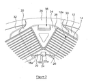
- the rotor assembly illustrated in Figures 3 to 5 comprises a rotor body 10 of elongate form, the rotor body defining a series of axially extending rotor poles 12. Between adjacent ones of the rotor poles 12 are defined a series of elongate rotor slots 16. As best shown in Figure 4 , each rotor pole 12 defines a pair of pole faces 12a which face toward respective ones of the slots 16. A winding 14 encircles each pole 12, the winding including regions lying adjacent each pole face 12a associated with the pole, thus each slot 16 includes parts of two adjacent ones of the windings 14.
- a compression member 22 of shallow wedge shaped form Adjacent the base 16a of each slot 16 is located a compression member 22 of shallow wedge shaped form.
- the compression member 22 is supported upon and held in spaced relationship to the base 16a of the slot 16 by compression means in the form of a pair of lock wedges 24.
- Recesses 16b, 22a are provided in the base 16a of the slot 16 and in the compression member 22 to accommodate the lock wedges 24.
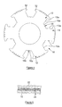
- the lock wedges 24 are of oppositely orientated, shallow tapering form, as shown in Figure 5 , with the result that relative longitudinal movement therebetween can be used to adjust the spacing of the compression member 22 from the base 16a of the slot 16.
- the compression member 22 bears against the radially inner part of the associated windings 14, bearing against parts of both of the windings 14 associated with the slot 16, an electrically insulating pad 26 being located therebetween in order to ensure that there is no conduction of electricity between adjacent ones of the windings 14. It will thus be appreciated that by appropriate adjustment of the positions of the lock wedges 24, the compression member 22 can be urged in an outward direction, thereby applying a compressive load to the windings 14 associated therewith urging the windings 14 in an outward direction, simulating the effects of centrifugal force upon the windings 14 and forcing the windings 14 to become properly seated in this direction.
- the rotor assembly further comprises an outer closure member 28 which spans the slot 16 and includes fingers 30 received beneath integral lips 32 provided at the tips of the poles 12, thereby resisting outward movement of the closure member 28 in use.
- the radially outer parts of the windings 14 bear against the fingers 30, thus the compression of the windings 14 serves to clamp the windings 14 and fingers against the lips 32 at the tips of the poles 12.
- a compression wedge 34 Inward of the closure member 28 is located a compression wedge 34 which is located in the slot 16 between the windings 14 associated with adjacent ones of the poles 12.
- a second lock wedge arrangement 36 is located between the closure member 28 and the wedge 34 and is operable to urge the wedge 34 in an inward direction. Such movement of the wedge 34 serves to compress the windings 14 against the pole faces 12a and so further assists in ensuring that the windings 14 are properly seated.
- An electrically insulating sleeve 38 extends over the wedge member 34 to assist in ensuring that the wedge member 34 is electrically insulated from the windings 14 thereby ensuring that the conduction of electricity between adjacent ones of the windings 14 is resisted
- the sleeve 38 further ensures that the closure member 28 is electrically insulated from the windings 14.
- Assembly of the rotor involves positioning the compression members 22 at the bases of respective ones of the slots 16. Once the compression members 22 have been so positioned, the windings 14 are wound around the poles 12. The closure members 28 are then slid into position from one end of the rotor, and the wedge members 34 and associated locking wedge arrangements 36 are loosely fitted into position. Once so assembled, the lock wedges 24 are inserted, one wedge 24 associated with each compression member 22 being inserted from each end of the rotor assembly.
- the co-operation between the wedges 24 applies a force to the compression member 22 urging the compression member 22 in an outward direction and, as described hereinbefore, such movement of the wedge member 22 serves to urge the windings 14 in an outward direction compressing the windings 14 against the inner surfaces of the fingers 30 of the closure members 28.
- the loading applied by the compression members 24 is such as to simulate the application of the centrifugal forces that occurs in use of the rotor assembly. Indeed the forces applied at this stage may well be higher than those typically experienced.
- the locking wedge arrangements 36 may similarly be manipulated to urge the wedge members 34 in an inward direction resulting in compression of the windings 14 against the pole faces 12a.
- an impregnation step in which the rotor assembly is impregnated with lacquer is conducted, the lacquer serving to secure the various components of the rotor assembly against movement.
- the impregnation step may be undertaken prior to testing of the rotor assembly by subjecting it to overspeed rotation, or alternatively it may be undertaken after such testing has been completed. If the impregnation step is undertaken after testing, then if the compression members 22 and lock wedges 24 are no longer loaded after the overspeed testing, it is possible that they could be removed prior to lacquering and so no longer present in the final product. However, it is not envisaged that the compression members 22 will generally be removed in this manner.
- the compression and wedge members 22, 34 will typically be of aluminium form in order to be of relatively low weight whilst of sufficient strength to perform the required functions. It is thought that most plastics materials will be insufficiently strong to perform in the required manner unless manufactured of increased dimensions.
- the lock wedges 24 and wedge arrangements 36 will preferably be of carbon fibre form for strength and dimensional accuracy whilst being of low weight.
- the closure member 28 could be machined from a titanium material in order to be of the desired strength whilst of low weight.
- this component will be manufactured by extruding an aluminium metal matrix composite material, preferably an aluminium silicon carbide mix containing up to 40% silicon carbide. Such a material is of low weight and of excellent strength and stiffness far exceeding that of titanium materials.
- both the compression member 22 and the wedge member 34 are urged by associated lock wedges 24 or wedge arrangements 36 to provide compression of the windings 14. It will be appreciated, however, that other forms of compression means may be provided to achieve such urging of the compression member 22 and/or wedge member 34 to achieve the desired compression of the windings 14.
Landscapes
- Engineering & Computer Science (AREA)
- Power Engineering (AREA)
- Insulation, Fastening Of Motor, Generator Windings (AREA)
Applications Claiming Priority (1)
| Application Number | Priority Date | Filing Date | Title |
|---|---|---|---|
| GBGB0915872.6A GB0915872D0 (en) | 2009-09-10 | 2009-09-10 | Rotor assembly |
Publications (2)
| Publication Number | Publication Date |
|---|---|
| EP2296256A2 true EP2296256A2 (de) | 2011-03-16 |
| EP2296256A3 EP2296256A3 (de) | 2012-08-22 |
Family
ID=41228117
Family Applications (1)
| Application Number | Title | Priority Date | Filing Date |
|---|---|---|---|
| EP10251555A Withdrawn EP2296256A3 (de) | 2009-09-10 | 2010-09-04 | Rotoranordnung |
Country Status (3)
| Country | Link |
|---|---|
| US (1) | US20110215669A1 (de) |
| EP (1) | EP2296256A3 (de) |
| GB (1) | GB0915872D0 (de) |
Cited By (3)
| Publication number | Priority date | Publication date | Assignee | Title |
|---|---|---|---|---|
| WO2013110580A1 (de) * | 2012-01-26 | 2013-08-01 | Continental Automotive Gmbh | Rotor für eine rotierende elektrische maschine und elektromotor |
| US9634526B2 (en) | 2012-01-26 | 2017-04-25 | Continental Automotive Gmbh | Rotor for a rotating electric machine and rotating electric machine |
| US9735642B2 (en) | 2012-01-26 | 2017-08-15 | Continental Automotive Gmbh | Rotor for a rotating electric machine |
Families Citing this family (1)
| Publication number | Priority date | Publication date | Assignee | Title |
|---|---|---|---|---|
| FR3032839B1 (fr) * | 2015-02-16 | 2018-05-04 | Alstom Transport Technologies | Rotor de moteur electrique et moteur electrique correspondant |
Citations (1)
| Publication number | Priority date | Publication date | Assignee | Title |
|---|---|---|---|---|
| EP1494335A1 (de) | 2003-06-24 | 2005-01-05 | Goodrich Control Systems Ltd | Rotoranordnung für dynamoelektrische Maschine |
Family Cites Families (16)
| Publication number | Priority date | Publication date | Assignee | Title |
|---|---|---|---|---|
| US3089049A (en) * | 1959-05-12 | 1963-05-07 | Gen Electric Canada | Salient pole rotor construction |
| US3500093A (en) * | 1968-02-05 | 1970-03-10 | Rotax Ltd | Dynamoelectric machine salient pole rotor with coil supports |
| SE333768B (de) * | 1968-10-07 | 1971-03-29 | Asea Ab | |
| JPS5489203A (en) * | 1977-12-27 | 1979-07-16 | Toshiba Corp | Winding support device for rotary electric machine |
| CH629344A5 (de) * | 1978-06-08 | 1982-04-15 | Bbc Brown Boveri & Cie | Vorrichtung zum abstuetzen der feldwicklung eines polrades mit ausgepraegten polen. |
| JPH0591689A (ja) * | 1991-09-26 | 1993-04-09 | Mitsubishi Electric Corp | 突極形回転電機の回転子 |
| US5524699A (en) * | 1994-02-03 | 1996-06-11 | Pcc Composites, Inc. | Continuous metal matrix composite casting |
| US5932948A (en) * | 1998-09-22 | 1999-08-03 | Caterpillar Inc. | Rotor V-block assembly |
| US6054790A (en) * | 1999-03-23 | 2000-04-25 | Emerson Electric Co. | V-block arrangement for a dynamo-electric machine |
| US6661133B2 (en) * | 2001-07-12 | 2003-12-09 | Eli Liebermann | Rotor cooling arrangement |
| US7015616B2 (en) * | 2002-04-01 | 2006-03-21 | Honeywell International, Inc. | System and method for providing coil retention in the rotor windings of a high speed generator |
| US6984910B2 (en) * | 2003-01-13 | 2006-01-10 | Honeywell International, Inc. | Generator with composite rotor coil retention components |
| US7015617B2 (en) * | 2003-07-29 | 2006-03-21 | Honeywell International, Inc. | High speed generator with rotor coil support assemblies secured to interlamination disks |
| EP1564865A1 (de) * | 2004-02-12 | 2005-08-17 | Siemens Aktiengesellschaft | Schenkelpolmaschine mit mindestens einer Polspule |
| GB2425663A (en) * | 2005-04-25 | 2006-11-01 | Newage Int Ltd | Wedging arrangement |
| GB0524363D0 (en) * | 2005-11-29 | 2006-01-04 | Goodrich Control Sys Ltd | Dynamo electric machine |
-
2009
- 2009-09-10 GB GBGB0915872.6A patent/GB0915872D0/en not_active Ceased
-
2010
- 2010-09-04 EP EP10251555A patent/EP2296256A3/de not_active Withdrawn
- 2010-09-09 US US12/878,441 patent/US20110215669A1/en not_active Abandoned
Patent Citations (1)
| Publication number | Priority date | Publication date | Assignee | Title |
|---|---|---|---|---|
| EP1494335A1 (de) | 2003-06-24 | 2005-01-05 | Goodrich Control Systems Ltd | Rotoranordnung für dynamoelektrische Maschine |
Cited By (6)
| Publication number | Priority date | Publication date | Assignee | Title |
|---|---|---|---|---|
| WO2013110580A1 (de) * | 2012-01-26 | 2013-08-01 | Continental Automotive Gmbh | Rotor für eine rotierende elektrische maschine und elektromotor |
| CN104160596A (zh) * | 2012-01-26 | 2014-11-19 | 大陆汽车有限公司 | 用于旋转的电机器的转子和电动机 |
| US9634526B2 (en) | 2012-01-26 | 2017-04-25 | Continental Automotive Gmbh | Rotor for a rotating electric machine and rotating electric machine |
| US9685833B2 (en) | 2012-01-26 | 2017-06-20 | Continental Automotive Gmbh | Rotor for a rotating electric machine and electric motor |
| US9735642B2 (en) | 2012-01-26 | 2017-08-15 | Continental Automotive Gmbh | Rotor for a rotating electric machine |
| CN104160596B (zh) * | 2012-01-26 | 2018-11-13 | 大陆汽车有限公司 | 用于旋转的电机器的转子和电动机 |
Also Published As
| Publication number | Publication date |
|---|---|
| US20110215669A1 (en) | 2011-09-08 |
| EP2296256A3 (de) | 2012-08-22 |
| GB0915872D0 (en) | 2009-10-14 |
Similar Documents
| Publication | Publication Date | Title |
|---|---|---|
| US6933648B2 (en) | Rotor assembly for dynamo electric machines | |
| EP3942677B1 (de) | Verbessertes herstellungsverfahren eines rotors | |
| EP2807728B1 (de) | Rotor für eine rotierende elektrische maschine | |
| JP6064923B2 (ja) | 積層鉄心の製造方法 | |
| EP2296256A2 (de) | Rotoranordnung | |
| JP2001518772A (ja) | 電動機回転子と電動機回転子の製造方法 | |
| WO2007010064A3 (es) | Procedimiento de fabricación de piezas huecas de grandes dimensiones a base de materiales compuestos | |
| US6282786B1 (en) | Method of making injection formed hybrid airfoil | |
| EP2560270A1 (de) | Halteband eines Läufers | |
| DE2739702C2 (de) | ||
| EP3204187B1 (de) | Verfahren zur montage von laufschaufeln an einer rotorscheibe sowie zugehörige spannvorrichtung zur durchführung eines solchen verfahrens | |
| EP2685615B1 (de) | Verbessertes Auswuchten eines Rotors | |
| EP2389512B1 (de) | Verfahren zur herstellung eines ein polrad umfassendes magnetsystems | |
| EP2730395A1 (de) | Verfahren zur Herstellung einer Welle eines Gasturbinentriebwerks | |
| WO2016185199A3 (en) | Composite shaft arrangement with load introduction elements | |
| EP4500667A1 (de) | Rotor einer elektrischen maschine | |
| EP2712061B1 (de) | Verfahren zur Herstellung eines Rotors für Elektromotoren | |
| US20150069657A1 (en) | Provisional Retention of Metal Sheet on a Mold by Microwelds | |
| DE102011089388A1 (de) | Rotor für eine Elektromaschine | |
| EP0977340B1 (de) | Rotor für eine dynamoelektrische Maschine | |
| US9982575B2 (en) | Hydraulic camshaft adjuster, at least two-part rotor, and method for producing a rotor of a hydraulic camshaft adjuster | |
| EP4039436A1 (de) | Verfahren zur herstellung eines windturbinenrotorblattelements mit einem metalleinsatz | |
| EP2401477A2 (de) | Verfahren zum anbringen bzw. herstellen eines geschlossenen deckbandes für eine laufbeschaufelung einer turbinenstufe sowie laufbeschaufelung | |
| JPH05171901A (ja) | タービンロータの分割および一体成形方法 | |
| GB2575906A (en) | Rotor |
Legal Events
| Date | Code | Title | Description |
|---|---|---|---|
| PUAI | Public reference made under article 153(3) epc to a published international application that has entered the european phase |
Free format text: ORIGINAL CODE: 0009012 |
|
| AK | Designated contracting states |
Kind code of ref document: A2 Designated state(s): AL AT BE BG CH CY CZ DE DK EE ES FI FR GB GR HR HU IE IS IT LI LT LU LV MC MK MT NL NO PL PT RO SE SI SK SM TR |
|
| AX | Request for extension of the european patent |
Extension state: BA ME RS |
|
| PUAL | Search report despatched |
Free format text: ORIGINAL CODE: 0009013 |
|
| AK | Designated contracting states |
Kind code of ref document: A3 Designated state(s): AL AT BE BG CH CY CZ DE DK EE ES FI FR GB GR HR HU IE IS IT LI LT LU LV MC MK MT NL NO PL PT RO SE SI SK SM TR |
|
| AX | Request for extension of the european patent |
Extension state: BA ME RS |
|
| RIC1 | Information provided on ipc code assigned before grant |
Ipc: H02K 3/52 20060101AFI20120713BHEP |
|
| STAA | Information on the status of an ep patent application or granted ep patent |
Free format text: STATUS: THE APPLICATION IS DEEMED TO BE WITHDRAWN |
|
| 18D | Application deemed to be withdrawn |
Effective date: 20130223 |