EP2296432A1 - Wärmeübertrager - Google Patents
Wärmeübertrager Download PDFInfo
- Publication number
- EP2296432A1 EP2296432A1 EP09290702A EP09290702A EP2296432A1 EP 2296432 A1 EP2296432 A1 EP 2296432A1 EP 09290702 A EP09290702 A EP 09290702A EP 09290702 A EP09290702 A EP 09290702A EP 2296432 A1 EP2296432 A1 EP 2296432A1
- Authority
- EP
- European Patent Office
- Prior art keywords
- heat exchanger
- electrically insulating
- plastic frame
- rib
- insulating plastic
- Prior art date
- Legal status (The legal status is an assumption and is not a legal conclusion. Google has not performed a legal analysis and makes no representation as to the accuracy of the status listed.)
- Granted
Links
Images



Classifications
-
- H—ELECTRICITY
- H05—ELECTRIC TECHNIQUES NOT OTHERWISE PROVIDED FOR
- H05B—ELECTRIC HEATING; ELECTRIC LIGHT SOURCES NOT OTHERWISE PROVIDED FOR; CIRCUIT ARRANGEMENTS FOR ELECTRIC LIGHT SOURCES, IN GENERAL
- H05B3/00—Ohmic-resistance heating
- H05B3/40—Heating elements having the shape of rods or tubes
- H05B3/42—Heating elements having the shape of rods or tubes non-flexible
- H05B3/48—Heating elements having the shape of rods or tubes non-flexible heating conductor embedded in insulating material
- H05B3/50—Heating elements having the shape of rods or tubes non-flexible heating conductor embedded in insulating material heating conductor arranged in metal tubes, the radiating surface having heat-conducting fins
-
- F—MECHANICAL ENGINEERING; LIGHTING; HEATING; WEAPONS; BLASTING
- F24—HEATING; RANGES; VENTILATING
- F24H—FLUID HEATERS, e.g. WATER OR AIR HEATERS, HAVING HEAT-GENERATING MEANS, e.g. HEAT PUMPS, IN GENERAL
- F24H3/00—Air heaters
- F24H3/02—Air heaters with forced circulation
- F24H3/04—Air heaters with forced circulation the air being in direct contact with the heating medium, e.g. electric heating element
- F24H3/0405—Air heaters with forced circulation the air being in direct contact with the heating medium, e.g. electric heating element using electric energy supply, e.g. the heating medium being a resistive element; Heating by direct contact, i.e. with resistive elements, electrodes and fins being bonded together without additional element in-between
- F24H3/0429—For vehicles
-
- F—MECHANICAL ENGINEERING; LIGHTING; HEATING; WEAPONS; BLASTING
- F24—HEATING; RANGES; VENTILATING
- F24H—FLUID HEATERS, e.g. WATER OR AIR HEATERS, HAVING HEAT-GENERATING MEANS, e.g. HEAT PUMPS, IN GENERAL
- F24H3/00—Air heaters
- F24H3/02—Air heaters with forced circulation
- F24H3/06—Air heaters with forced circulation the air being kept separate from the heating medium, e.g. using forced circulation of air over radiators
- F24H3/08—Air heaters with forced circulation the air being kept separate from the heating medium, e.g. using forced circulation of air over radiators by tubes
- F24H3/081—Air heaters with forced circulation the air being kept separate from the heating medium, e.g. using forced circulation of air over radiators by tubes using electric energy supply
-
- F—MECHANICAL ENGINEERING; LIGHTING; HEATING; WEAPONS; BLASTING
- F24—HEATING; RANGES; VENTILATING
- F24H—FLUID HEATERS, e.g. WATER OR AIR HEATERS, HAVING HEAT-GENERATING MEANS, e.g. HEAT PUMPS, IN GENERAL
- F24H9/00—Details
- F24H9/18—Arrangement or mounting of grates or heating means
- F24H9/1854—Arrangement or mounting of grates or heating means for air heaters
- F24H9/1863—Arrangement or mounting of electric heating means
-
- F—MECHANICAL ENGINEERING; LIGHTING; HEATING; WEAPONS; BLASTING
- F24—HEATING; RANGES; VENTILATING
- F24H—FLUID HEATERS, e.g. WATER OR AIR HEATERS, HAVING HEAT-GENERATING MEANS, e.g. HEAT PUMPS, IN GENERAL
- F24H9/00—Details
- F24H9/18—Arrangement or mounting of grates or heating means
- F24H9/1854—Arrangement or mounting of grates or heating means for air heaters
- F24H9/1863—Arrangement or mounting of electric heating means
- F24H9/1872—PTC resistor
Definitions
- the invention relates to a heat exchanger according to the preamble of claim 1.
- Electrical heaters usually use a plurality of PTC elements, which are accommodated in at least two contact plates arranged on both sides or are pressed or glued therein.
- the heating elements are supplied by the battery systems of the motor vehicles, which have a high voltage, these high voltages can cause safety problems, and it is necessary to electrically isolate the individual heating elements.
- a receiving device for ceramic heating elements which consists of a frame made of plastic or of a polymer ceramic or ceramic, so that the frame is electrically insulating.
- the frame has along its length parallel longitudinal webs, which have inwardly directed longitudinal grooves.
- the longitudinal webs are connected by spaced longitudinally arranged transverse webs.
- the heater is inserted into the recesses between the longitudinal and transverse webs.
- a heat exchanger in particular an electric heater for a motor vehicle, having at least one heating element, which has at least one PTC element and at least a first contact plate and at least a second contact plate is provided, wherein the at least one PTC element between the at least one first Contact plate and the at least one second contact plate is fixed, and wherein the at least one heating element is arranged completely in an electrically insulating plastic frame.
- the at least one PTC element is fixed by gluing between the at least one first contact sheet and the at least one second contact sheet.
- the fixation by gluing makes additional elements, such as holding frames and the like superfluous.
- the at least one first contact plate and the at least one second contact plate each have a connector.
- the electrically insulating plastic frame is arranged between two rib elements.
- each of the two rib members respectively extends on one of two longitudinal sides of the electrically insulating plastic frame.
- the electrically insulating plastic frame is designed as a rectangular hollow profile.
- the electrically insulating plastic frame has a length which substantially corresponds to the length of the at least one heating element.
- the electrically insulating plastic frame has a width which substantially corresponds to the width of the at least one heating element.
- the electrically insulating plastic frame has a height which substantially corresponds to the height of the at least one heating element.
- the electrically insulating plastic frame has a height which substantially corresponds to the height of the at least one heating element.
- the two rib elements respectively belong to a rib block, which in each case has two rib elements and a sheet metal element arranged between the two rib elements.
- each rib block is provided at its opposite outer surfaces, which are opposite the longitudinal sides of the electrically insulating plastic frame, with a further plate-like sheet metal element.
- the rib block has exactly one rib element, wherein a further plate-like sheet metal element is arranged on its opposite outer surfaces, which lie opposite the longitudinal sides of the electrically insulating plastic frame.
- these sheet metal elements can also be omitted, so that the rib block directly adjoins the plastic frame.
- each rib member is formed as a corrugated fin member.
- each rib block is bonded to the respective rib members of the rib block. This also provides a simple and inexpensive solution for fixing or mounting a ribbed block assembly.
- the electrically insulating plastic frame in particular a plurality of electrically insulating plastic frame, fixed in a housing frame of the heat exchanger. It is also possible according to yet another preferred embodiment, the plurality of electrically insulating plastic frame integrally or integrally formed with the housing frame of the heat exchanger.
- Fig.1 shows a front view of the items of a heating element 1 according to the prior art.
- the heating element 1 consists of a plate-shaped first contact plate 2 and a plate-shaped second contact plate 3, which run parallel and together form a frame. Between the first contact plate 2 and the second contact plate 3, a plurality of PTC elements 4, here 7 pieces, arranged, which are isolated by a sealing profile 5 and secured against slipping.
- the sealing profile 5 is as an endless profile made of silicone, cut to the length of the heating element 1, and in which perforations 6 are stamped, in which the PTC elements 4 are positioned and kept at a distance.
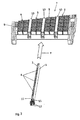
- Fig. 2 shows a lower portion of a heat exchanger 7 in perspective view according to an embodiment.
- the heat exchanger 7 comprises a housing frame 8 in which four rib blocks 9 are accommodated, each with arranged between two rib blocks 9 electrically insulating plastic frame 10.
- the electrically insulating plastic frame 10 are formed as separate components and each fixed to the housing frame 8
- Each electrically insulating plastic frame 10 is formed as a rectangular hollow profile and thus forms a receptacle for each heating element 1, which substantially the dimensions of the plastic frame 10 corresponds or is slightly smaller.
- each of the first and second contact sheets 2, 3 has a connector 12 for connecting the first and second contact sheets 2, 3 and the associated PTC elements 4 to a power supply via connectable cables or bus bars (not shown) ,
- Fig. 3 shows a rib block 9, which consists of two rib elements 13, 13 ', which are formed as corrugated ribs, and three plate-shaped sheet metal elements 14.
- One of the three sheet metal elements 14 is arranged between the two rib elements 13, 13 'and in each case a further one is arranged on the respective outer surface of the rib elements 13, 13'.
- the fixing of the sheet metal elements 14 to the rib elements 13, 13 ' also takes place by gluing by means of a good thermal conductivity adhesive.
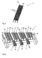
- Fig. 4 shows a lower portion of a heat exchanger 7 in a perspective view according to an embodiment, wherein the heat exchanger 7 has three electrically insulating plastic frame 10, in each of which a heating element 1 is completely received, so that only the respective connectors 12 protrude from the electrically insulating plastic frame 10.
- Fig. 5 shows a perspective view of a heat exchanger 7 according to an embodiment, wherein the heating elements 1 in the respective electrically insulating plastic frame 10, which are formed in the embodiment integral with the housing frame 8, are added.
Landscapes
- Engineering & Computer Science (AREA)
- Physics & Mathematics (AREA)
- Thermal Sciences (AREA)
- Chemical & Material Sciences (AREA)
- Combustion & Propulsion (AREA)
- Mechanical Engineering (AREA)
- General Engineering & Computer Science (AREA)
- Air-Conditioning For Vehicles (AREA)
- Resistance Heating (AREA)
Abstract
Description
- Die Erfindung betrifft einen Wärmeübertrager gemäß dem Oberbegriff des Anspruchs 1.
- Um den Innenraum eines Kraftfahrzeugs aufzuwärmen, ist es meist in der Startphase oder bei geringen Außentemperaturen notwendig, zuzuheizen, da die heutzutage eingesetzten verbrauchsoptimierten Fahrzeuge oder auch insbesondere Elektro- und Hybridfahrzeuge, nicht ausreichend Abwärme produzieren, um einen Fahrzeuginnenraum zu heizen. Hierzu müssen zusätzlich elektrische Zuheizer eingesetzt werden, die kostengünstig, spontan spürbar - das heißt, die elektrische Leistung wird sofort in Wärme umgesetzt - und platzsparend sind.
- Bei diesen elektrischen Zuheizern erfolgt die Umwandlung von elektrischer Energie aus dem Bordnetz des Fahrzeugs in Wärme in der Regel in einem PTC-Element (Positive Temperature Coefficient). Dieser Kaltleiter aus Keramik ist ein sehr stark temperaturabhängiger Halbleiterwiderstand. Das heißt, dass mit zunehmender Temperatur der Widerstand des Keramik-Elements sehr stark zunimmt. Dadurch stellt sich unabhängig von den Randbedingungen - wie z. B. angelegte Spannung, Nominalwiderstand, Luftmenge über dem PTC-Element - eine sehr gleichmäßige Oberflächentemperatur am PTC-Element ein, welches den Vorteil hat, dass eine Überhitzung verhindert wird, wie sie z. B. bei einem normalen Wärme abgebenden Heizdraht auftreten könnte, da hier unabhängig von den Randbedingungen immer der gleiche Widerstand und dadurch elektrische Heizleistung eingebracht wird.
- Elektrische Zuheizer setzen in der Regel eine Vielzahl von PTC-Elementen ein, die in zumindest zwei beidseitig angeordneten Kontaktblechen aufgenommen bzw. darin verpresst oder verklebt sind. Da jedoch die Heizelemente von den Batteriesystemen der Kraftfahrzeuge, welche eine hohe Spannung aufweisen, versorgt werden, können diese hohen Spannungen Sicherheitsprobleme verursachen, und es ist erforderlich die einzelnen Heizelemente elektrisch zu isolieren.
- Zur elektrischen Isolierung ist es im Stand der Technik bekannt, beispielsweise ein leiterförmiges Dichtprofil einzusetzen, welches den Abstand zwischen den Kontaktblechen und den einzelnen PTC-Elementen der Heizeiemente abdichtet.
- In
DE 103 33 451 A1 ist eine Aufnahmevorrichtung für Keramik-Heizelemente beschrieben, welche einen Rahmen aus Kunststoff oder aus einer Polymerkeramik oder Keramik besteht, so dass der Rahmen elektrisch isolierend ist. Der Rahmen weist über seine Länge parallel verlaufende Längsstege auf, die nach innen hin gerichtete Längsnuten aufweisen. Die Längsstege sind durch mit Abstand in Längsrichtung angeordneten Querstegen verbunden. Die Heizvorrichtung wird in die Ausnehmungen zwischen den Längs- und Querstegen eingelegt. - Die oben beschriebenen Lösungen dichten jedoch nur teilweise, d. h. nicht bis zum elektrischen Versorgungspunkt, die stromführenden Teile des Heizelements ab.
- Daher ist es die Aufgabe der vorliegenden Erfindung, eine effektive und einfache Isolierung der verklebten Heizelemente in einem Wärmeübertrager vorzusehen.
- Die Aufgabe der vorliegenden Erfindung wird durch einen Wärmeübertrager mit den Merkmalen gemäß Anspruch 1 gelöst. Vorteilhafte Weiterbildungen der vorliegenden Erfindung sind in den Unteransprüchen definiert.
- Erfindungsgemäß wird ein Wärmeübertrager, insbesondere ein elektrischer Zuheizer für ein Kraftfahrzeug, mit zumindest einem Heizelement, welches zumindest ein PTC-Element und zumindest ein erstes Kontaktblech und zumindest ein zweites Kontaktblech aufweist, vorgesehen, wobei das zumindest eine PTC-Element zwischen dem zumindest einen ersten Kontaktblech und dem zumindest einen zweiten Kontaktblech fixiert ist, und wobei das zumindest eine Heizelement vollständig in einem elektrisch isolierenden Kunststoffrahmen angeordnet ist. Diese Konfiguration bietet eine Lösung zur elektrischen Isolierung der Heizelemente, welche weder mehrere noch zusätzliche Teile erfordert. Somit wird gemäß der Erfindung eine deutliche Vereinfachung der Isolierung erzielt, wodurch auch die Herstellungskosten reduziert werden können.
- Gemäß einer bevorzugten Ausführungsform ist das zumindest eine PTC-Element zwischen dem zumindest einen ersten Kontaktblech und dem zumindest einen zweiten Kontaktblech mittels Kleben fixiert. Die Fixierung mittels Kleben macht zusätzliche Elemente, wie Halterahmen und dergleichen überflüssig.
- Gemäß noch einer bevorzugten Ausführungsform weist das zumindest eine erste Kontaktblech und das zumindest eine zweite Kontaktblech jeweils einen Konnektor auf.
- Gemäß noch einer weiteren Ausführungsform ist der elektrisch isolierende Kunststoffrahmen zwischen zwei Rippenelementen angeordnet.
- Vorzugsweise erstreckt sich jedes der zwei Rippenelemente jeweilig auf einer von zwei Längsseiten des elektrisch isolierenden Kunststoffrahmens.
- Besonders bevorzugt ist es, wenn der elektrisch isolierende Kunststoffrahmen als rechteckiges Hohlprofil ausgebildet ist.
- Gemäß einer weiteren bevorzugten Ausführungsform weist der elektrisch isolierende Kunststoffrahmen eine Länge auf, welche im Wesentlichen der Länge des zumindest einen Heizelements entspricht.
- Es ist darüber hinaus bevorzugt, wenn der elektrisch isolierende Kunststoffrahmen eine Breite aufweist, welche im Wesentlichen der Breite des zumindest einen Heizelements entspricht.
- Noch bevorzugter weist der elektrisch isolierende Kunststoffrahmen eine Höhe auf, welche im Wesentlichen der Höhe des zumindest einen Heizelements entspricht. Durch Ausbilden des elektrisch isolierenden Kunststoffrahmens als rechteckiges Hohlprofil, welches im Wesentlichen die Abmessungen des Heizelements aufweist bzw. geringfügig größer als das Heizelement ist, so dass dieses in dem Hohlprofil aufnehmbar ist, wird einerseits eine platzsparende und andererseits eine einfache Lösung zur elektrischen Isolierung der Heizelemente bereitgestellt.
- Gemäß einer weiteren bevorzugten Ausführungsform gehören die zwei Rippenelemente jeweilig einem Rippenblock an, welcher jeweils zwei Rippenelemente und ein zwischen den zwei Rippenelementen angeordnetes Blechelement aufweist.
- Gemäß noch einer weiteren bevorzugten Ausführungsform ist jeder Rippenblock an seinen gegenüberliegenden Außenflächen, welche den Längsseiten des elektrisch isolierenden Kunststoffrahmens gegenüberliegen, mit einem weiteren plattenartigen Blechelement versehen.
- Gemäß noch einer weiteren bevorzugten Ausführungsform weist der Rippenblock genau ein Rippenelement auf, wobei an seinen gegenüberliegenden Außenflächen, welche den Längsseiten des elektrisch isolierenden Kunststoffrahmens gegenüberliegen, ein weiteres plattenartigen Blechelement angeordnet ist. Alternativ können diese Blechelemente auch entfallen, so dass der Rippenblock unmittelbar an den Kunststoffrahmen grenzt.
- Gemäß noch einer weiteren bevorzugten Ausführungsform ist jedes Rippenelement als Wellrippenelement ausgebildet.
- Vorzugsweise sind die Blechelemente eines jeden Rippenblocks mit den jeweiligen Rippenelementen des Rippenblocks verklebt. Dies bietet ebenfalls eine einfache und kostengünstige Lösung zur Fixierung bzw. Montage einer Rippenblock-Baugruppe.
- Es ist besonders bevorzugt, wen eine Vielzahl von Rippenblöcken und eine Vielzahl von in dem elektrisch isolierenden Kunststoffrahmen angeordneten Heizelementen in dem Wärmeübertrager vorgesehen sind.
- Darüber hinaus ist vorzugsweise der elektrisch isolierende Kunststoffrahmen, insbesondere eine Vielzahl von elektrisch isolierenden Kunststoffrahmen, in einem Gehäuserahmen des Wärmeübertragers fixiert. Es ist auch gemäß noch einer weiteren bevorzugten Ausführungsform möglich, die Vielzahl von elektrisch isolierenden Kunststoffrahmen einstückig bzw. integral mit dem Gehäuserahmen des Wärmeübertragers auszubilden.
- Im Folgenden wird die Erfindung anhand eines Ausführungsbeispiels unter Bezugnahme auf die Zeichnung detailliert erläutert. In der Zeichnung zeigen:
- Fig.1
- eine Vorderansicht der Einzelteile eines Heizelements gemäß dem Stand der Technik;
- Fig. 2
- eine perspektivische Ansicht eines unteren Abschnitts eines Wär- meübertragers gemäß einer Ausführungsform ohne darin montierte Heizelemente;
- Fig. 3
- einen Rippenblock eines Wärmeübertragers gemäß einer Ausfüh- rungsform;
- Fig. 4
- eine perspektivische Ansicht eines unteren Abschnitts eines Wär- meübertragers gemäß einer Ausführungsform mit darin montierten Heizelementen;
- Fig. 5
- eine perspektivische Ansicht eines Wärmeübertragers gemäß einer Ausführungsform mit abgenommenen Deckelelement;
- Fig. 6
- eine Vorderansicht des Wärmeübertragers von
Fig. 5 mit aufgesetz- tem Deckelelement. -
Fig.1 zeigt eine Vorderansicht der Einzelteile eines Heizelements 1 gemäß dem Stand der Technik. Das Heizelement 1 besteht aus einem plattenförmigen ersten Kontaktblech 2 und einem plattenförmigen zweiten Kontaktblech 3, die parallel verlaufen und zusammen einen Rahmen bilden. Zwischen dem ersten Kontaktblech 2 und dem zweiten Kontaktblech 3 sind eine Vielzahl von PTC-Elementen 4, hier 7 Stück, angeordnet, die durch ein Dichtprofil 5 isoliert und gegen Verrutschen gesichert werden. Das Dichtprofil 5 ist als ein Endlosprofil, welches aus Silikon besteht, hergestellt, welches auf die Länge des Heizelements 1 zugeschnitten ist, und in dem Durchbrechungen 6 eingestanzt sind, in denen die PTC-Elemente 4 positioniert und auf Abstand gehalten sind. -
Fig. 2 zeigt einen unteren Abschnitt eines Wärmeübertragers 7 in perspektivischer Ansicht gemäß einer Ausführungsform. Der Wärmeübertrager 7 umfasst einen Gehäuserahmen 8, in welchem vier Rippenblöcke 9 mit jeweils zwischen zwei Rippenblöcken 9 angeordneten elektrisch isolierenden Kunststoffrahmen 10 untergebracht sind. In der hier dargestellten Ausführungsform sind die elektrisch isolierenden Kunststoffrahmen 10 als separate Bauteile gebildet und jeweils an dem Gehäuserahmen 8 fixiert Jeder elektrisch isolierende Kunststoffrahmen 10 ist als rechteckiges Hohlprofil ausgebildet und bildet somit eine Aufnahme für jeweils ein Heizelement 1, welches im Wesentlichen den Abmessungen des Kunststoffrahmens 10 entspricht bzw. geringfügig kleiner ist. Wie in der Figur dargestellt ist, wird jeweils ein Heizelement 1 in Pfeilrichtung P in den elektrisch isolierenden Kunststoffrahmen 10 eingeführt, so dass es in montiertem Zustand vollständig durch den elektrisch isolierenden Kunststoffrahmen 10 umgeben ist bzw. vollständig darin aufgenommen ist. Das Heizelement 1 umfasst in der Ausführungsform drei PTC-Elemente 4, welche sandwichartig zwischen den ersten und zweiten Kontaktblechen 2, 3 angeordnet ist. Zur Fixierung der drei PTC-Elemente 4 zwischen dem ersten Kontaktblech 2 und dem zweiten Kontaktblech 3 sind diese mit den PTC-Elementen 4 verklebt, beispielsweise mittels eines Zwei-Komponenten-Klebers, welcher gut wärmeleitfähig und auch elektrisch leitend ist. An einem Endabschnitt 11 weist jedes der ersten und zweiten Kontaktbleche 2, 3 einen Konnektor 12 zum Verbinden der ersten und zweiten Kontaktbleche 2, 3 bzw. der damit verbundenen PTC-Elemente 4 mit einer Stromversorgung über daran anschließbare Kabel oder Stromschienen (nicht dargestellt) auf. -
Fig. 3 zeigt einen Rippeblock 9, welcher aus zwei Rippenelementen 13, 13', welche als Wellrippen ausgebildet sind, und aus drei plattenförmigen Blechelementen 14 besteht. Eines der drei Blechelemente 14 ist zwischen den zwei Rippenelementen 13, 13' angeordnet und jeweils ein weiteres ist auf der jeweiligen Außenfläche der Rippenelemente 13, 13' angeordnet. Die Fixierung der Blechelemente 14 an den Rippenelementen 13, 13' erfolgt ebenfalls durch Kleben mittels eines gut wärmeleitfähigen Klebers. -
Fig. 4 zeigt einen unteren Abschnitt eines Wärmeübertragers 7 in perspektivischer Ansicht gemäß einer Ausführungsform, wobei der Wärmeübertrager 7 drei elektrisch isolierende Kunststoffrahmen 10 aufweist, in welchen jeweils ein Heizelement 1 vollständig aufgenommen ist, so dass lediglich die jeweiligen Konnektoren 12 aus dem elektrisch isolierenden Kunststoffrahmen 10 abragen. -
Fig. 5 zeigt eine perspektivische Ansicht eines Wärmeübertragers 7 gemäß einer Ausführungsform, wobei die Heizelemente 1 in die jeweiligen elektrisch isolierenden Kunststoffrahmen 10, welche in der Ausführungsform integral mit dem Gehäuserahmen 8 ausgebildet sind, aufgenommen sind. Ein Deckelelement 15, in welchem hier nicht dargestellte Kabel oder Stromschienen untergebracht sind, welche die Konnektoren 12 der ersten und zweiten Kontaktbleche 2, 3 und die damit verbundenen PTC-Elemente 4 mit einer ebenfalls nicht dargestellten Stromversorgung verbinden, ist in einem von dem Gehäuserahmen 8 abgenommen Zustand dargestellt, wohingegenFig. 6 schließlich eine Vorderansicht des Wärmeübertragers 7 vonFig. 5 zeigt, wobei das Deckelelement 15 auf den Gehäuserahmen 8 aufgesetzt ist. - Insgesamt kann mit dem so ausgebildeten Wärmeübertrager 7 eine sichere und einfache Isolierung der Heizelemente 1 vorgesehen werden.
-
- 1
- Heizelement
- 2
- erstes Kontaktblech
- 3
- zweites Kontaktblech
- 4
- PTC-Element
- 5
- Dichtprofil
- 6
- Durchbrechung
- 7
- Wärmeübertrager
- 8
- Gehäuserahmen
- 9
- Rippenblock
- 10
- elektrisch isolierender Kunststoffrahmen
- 11
- Endabschnitt
- 12
- Konnektor
- 13, 13'
- Rippenelement
- 14
- Blechelement
- 15
- Deckelelement
Claims (15)
- Wärmeübertrager (7), insbesondere elektrischer Zuheizer für ein Kraftfahrzeug, mit zumindest einem Heizelement (1), welches zumindest ein PTC-Element (4) und zumindest ein erstes Kontaktblech (2) und ein zweites Kontaktblech (3) aufweist, wobei das zumindest eine PTC-Element (4) zwischen dem zumindest einen ersten Kontaktblech (2) und dem zumindest einem zweiten Kontaktblech (3) fixiert ist, dadurch gekennzeichnet, dass das zumindest eine Heizelement (1) vollständig in einem elektrisch isolierenden Kunststoffrahmen (10) angeordnet ist.
- Wärmeübertrager (7) nach Anspruch 1, dadurch gekennzeichnet, dass das zumindest eine PTC-Element (4) zwischen dem zumindest einen ersten Kontaktblech (2) und dem zumindest einen zweiten Kontaktblech (3) mittels Kleben fixiert ist.
- Wärmeübertrager (7) nach Anspruch 1 oder 2, dadurch gekennzeichnet, dass das zumindest eine erste Kontaktblech (2) und das zumindest eine zweite Kontaktblech (3) jeweils mit einem Konnektor (12) versehen ist.
- Wärmeübertrager (7) nach einem oder mehreren der Ansprüche 1 bis 3, dadurch gekennzeichnet, dass der elektrisch isolierende Kunststoffrahmen (10) zwischen zwei Rippenelementen (13, 13') angeordnet ist.
- Wärmeübertrager (7) nach Anspruch 4, dadurch gekennzeichnet, dass sich jedes der zwei Rippenelemente (13, 13') jeweilig auf einer von zwei gegenüberliegenden Längsseiten des elektrisch isolierenden Kunststoffrahmens (10) erstreckt.
- Wärmeübertrager (7) nach einem oder mehreren der Ansprüche 1 bis 5, dadurch gekennzeichnet, dass der elektrisch isolierende Kunststoffrahmen (10) als rechteckiges Hohlprofil ausgebildet ist.
- Wärmeübertrager (7) nach einem oder mehreren der Ansprüche 1 bis 6, dadurch gekennzeichnet, dass der elektrisch isolierende Kunststoffrahmen (10) eine Länge aufweist, welche im Wesentlichen der Länge des zumindest einen Heizelements (1) entspricht.
- Wärmeübertrager (7) nach einem oder mehreren der Ansprüche 1 bis 7, dadurch gekennzeichnet, dass der elektrisch isolierende Kunststoffrahmen (10) eine Breite aufweist, welche im Wesentlichen der Breite des zumindest einen Heizelements (1) entspricht.
- Wärmeübertrager (7) nach einem oder mehreren der Ansprüche 1 bis 8, dadurch gekennzeichnet, dass der elektrisch isolierende Kunststoffrahmen (10) eine Höhe aufweist, welche im Wesentlichen der Höhe des zumindest einen Heizelements (1) entspricht.
- Wärmeübertrager (7) nach einem oder mehreren der Ansprüche 4 bis 9, dadurch gekennzeichnet, dass die zwei Rippenelemente (13, 13') jeweilig einem Rippenblock (9) angehören, welcher jeweils zwei Rippenelemente (13, 13') und ein zwischen den zwei Rippenelementen (13, 13') angeordnetes Blechelement (14) aufweist.
- Wärmeübertrager (7) nach Anspruch 10, dadurch gekennzeichnet, dass jeder Rippenblock (9) an seinen gegenüberliegenden Außenflächen, welche den Längsseiten des elektrisch isolierenden Kunsstoffrahmens (10) gegenüberliegen, mit einem weiteren plattenartigen Blechelement (14) versehen sind.
- Wärmeübertrager (7) nach einem oder mehreren der Ansprüche 4 bis 11, dadurch gekennzeichnet, dass jedes Rippenelement (13, 13') als Wellrippenelement ausgebildet ist.
- Wärmeübertrager (7) nach Anspruch 11 oder 12, dadurch gekennzeichnet, dass die Blechelemente (14) eines jeden Rippenblocks (9) mit den jeweiligen Rippenelementen (13, 13') des Rippenblocks (9) verklebt sind.
- Wärmeübertrager (7) nach einem oder mehreren der Ansprüche 11 bis 13, dadurch gekennzeichnet, dass eine Vielzahl von Rippenblöcken (9) und eine Vielzahl von in dem elektrisch isolierenden Kunststoffrahmen (10) angeordneten Heizelementen (1) in dem Wärmeübertrager (7) vorgesehen ist.
- Wärmeübertrager (7) nach einem oder mehreren der Ansprüche 1 bis 14, dadurch gekennzeichnet, dass der elektrisch isolierende Kunststoffrahmen (10), insbesondere eine Vielzahl von elektrisch isolierenden Kunststoffrahmen (10), in einem Gehäuserahmen (8) des Wärmeübertragers (7) fixiert ist.
Priority Applications (1)
| Application Number | Priority Date | Filing Date | Title |
|---|---|---|---|
| EP09290702.1A EP2296432B1 (de) | 2009-09-15 | 2009-09-15 | Wärmeübertrager |
Applications Claiming Priority (1)
| Application Number | Priority Date | Filing Date | Title |
|---|---|---|---|
| EP09290702.1A EP2296432B1 (de) | 2009-09-15 | 2009-09-15 | Wärmeübertrager |
Publications (2)
| Publication Number | Publication Date |
|---|---|
| EP2296432A1 true EP2296432A1 (de) | 2011-03-16 |
| EP2296432B1 EP2296432B1 (de) | 2018-01-03 |
Family
ID=41508749
Family Applications (1)
| Application Number | Title | Priority Date | Filing Date |
|---|---|---|---|
| EP09290702.1A Not-in-force EP2296432B1 (de) | 2009-09-15 | 2009-09-15 | Wärmeübertrager |
Country Status (1)
| Country | Link |
|---|---|
| EP (1) | EP2296432B1 (de) |
Cited By (3)
| Publication number | Priority date | Publication date | Assignee | Title |
|---|---|---|---|---|
| DE102010020070A1 (de) * | 2010-05-09 | 2011-11-10 | Esw Gmbh | Heizmodul zur Erwärmung strömender Medien und Verfahren zu seiner Herstellung |
| US10363797B2 (en) | 2013-06-03 | 2019-07-30 | Borgwarner Ludwigsburg Gmbh | Vehicle heater |
| DE102020203390A1 (de) | 2020-03-17 | 2021-09-23 | Eberspächer catem Hermsdorf GmbH & Co. KG | Elektrische heizeinrichtung und verfahren zu deren herstellung |
Citations (4)
| Publication number | Priority date | Publication date | Assignee | Title |
|---|---|---|---|---|
| DE3208802A1 (de) * | 1980-12-13 | 1983-09-22 | C.S. Fudickar Kg, 5600 Wuppertal | Elektrische heizvorrichtung fuer beheizte apparate |
| EP1182908A1 (de) * | 2000-08-25 | 2002-02-27 | Catem GmbH & Co.KG | PTC-Heizvorrichtung mit Klebestoff |
| DE10333451A1 (de) | 2003-04-12 | 2004-11-25 | Eichenauer Heizelemente Gmbh & Co. Kg | Vorrichtung zur Aufnahme von Keramik-Heizelementen und Verfahren zur Herstellung einer solchen |
| EP1916873A1 (de) * | 2006-10-25 | 2008-04-30 | Catem GmbH & Co.KG | Wärmeerzeugendes Element für eine elektrische Heizvorrichtung und Verfahren zur Herstellung derselben |
-
2009
- 2009-09-15 EP EP09290702.1A patent/EP2296432B1/de not_active Not-in-force
Patent Citations (4)
| Publication number | Priority date | Publication date | Assignee | Title |
|---|---|---|---|---|
| DE3208802A1 (de) * | 1980-12-13 | 1983-09-22 | C.S. Fudickar Kg, 5600 Wuppertal | Elektrische heizvorrichtung fuer beheizte apparate |
| EP1182908A1 (de) * | 2000-08-25 | 2002-02-27 | Catem GmbH & Co.KG | PTC-Heizvorrichtung mit Klebestoff |
| DE10333451A1 (de) | 2003-04-12 | 2004-11-25 | Eichenauer Heizelemente Gmbh & Co. Kg | Vorrichtung zur Aufnahme von Keramik-Heizelementen und Verfahren zur Herstellung einer solchen |
| EP1916873A1 (de) * | 2006-10-25 | 2008-04-30 | Catem GmbH & Co.KG | Wärmeerzeugendes Element für eine elektrische Heizvorrichtung und Verfahren zur Herstellung derselben |
Cited By (3)
| Publication number | Priority date | Publication date | Assignee | Title |
|---|---|---|---|---|
| DE102010020070A1 (de) * | 2010-05-09 | 2011-11-10 | Esw Gmbh | Heizmodul zur Erwärmung strömender Medien und Verfahren zu seiner Herstellung |
| US10363797B2 (en) | 2013-06-03 | 2019-07-30 | Borgwarner Ludwigsburg Gmbh | Vehicle heater |
| DE102020203390A1 (de) | 2020-03-17 | 2021-09-23 | Eberspächer catem Hermsdorf GmbH & Co. KG | Elektrische heizeinrichtung und verfahren zu deren herstellung |
Also Published As
| Publication number | Publication date |
|---|---|
| EP2296432B1 (de) | 2018-01-03 |
Similar Documents
| Publication | Publication Date | Title |
|---|---|---|
| EP1768458B1 (de) | Wärmeerzeugendes Element einer Heizvorrichtung | |
| EP2428746B2 (de) | Wärmeübertrager | |
| EP1318694B1 (de) | Elektrische Heizvorrichtung | |
| EP1872986B1 (de) | Elektrische Heizvorrichtung | |
| EP3079442B1 (de) | Elektrische heizvorrichtung und rahmen hierfür | |
| EP1963753B1 (de) | Elektrische heizvorrichtung, insbesondere für automobile | |
| DE102011077922A1 (de) | Wärmeübertrager | |
| EP0705055A2 (de) | Elektrische Heizeinrichtung, insbesondere für ein Kraftfahrzeug | |
| DE112016000688B4 (de) | Elektrische Heizvorrichtung | |
| EP3143654B1 (de) | Verbindung zwischen zwei batteriemodulen eines batteriesystems | |
| EP2428747A1 (de) | Wärmeübertrager | |
| EP2395295A1 (de) | Wärmeübertrager | |
| EP2346304B1 (de) | Wärmeübertrager | |
| EP2296432B1 (de) | Wärmeübertrager | |
| DE102006018150B4 (de) | Heizeinrichtung | |
| EP2276321B1 (de) | Wärmeübertrager | |
| EP2393336A1 (de) | Wärmeübertrager | |
| DE102013015786A1 (de) | Batterie mit einer Anzahl elektrisch seriell und/oder parallel miteinander verschalteter Einzelzellen | |
| EP1884383A1 (de) | Elektrische Heizungsanordnung, insbesondere für ein Kraftfahrzeug | |
| EP1503153B1 (de) | Vorrichtung zum Austausch von Wärme | |
| DE102020202195A1 (de) | Elektrische Heizeinrichtung | |
| EP2293648B1 (de) | Wärmeübertrager | |
| DE102023111569A1 (de) | Elektrischer Heizer für ein Fahrzeug | |
| DE102013015753A1 (de) | Batterie und Zellblock für eine Batterie | |
| EP2505396B1 (de) | Kraftfahrzeugklimaanlage |
Legal Events
| Date | Code | Title | Description |
|---|---|---|---|
| PUAI | Public reference made under article 153(3) epc to a published international application that has entered the european phase |
Free format text: ORIGINAL CODE: 0009012 |
|
| AK | Designated contracting states |
Kind code of ref document: A1 Designated state(s): AT BE BG CH CY CZ DE DK EE ES FI FR GB GR HR HU IE IS IT LI LT LU LV MC MK MT NL NO PL PT RO SE SI SK SM TR |
|
| AX | Request for extension of the european patent |
Extension state: AL BA RS |
|
| 17P | Request for examination filed |
Effective date: 20110916 |
|
| 17Q | First examination report despatched |
Effective date: 20111006 |
|
| RAP1 | Party data changed (applicant data changed or rights of an application transferred) |
Owner name: MAHLE BEHR FRANCE ROUFFACH S.A.S |
|
| GRAP | Despatch of communication of intention to grant a patent |
Free format text: ORIGINAL CODE: EPIDOSNIGR1 |
|
| INTG | Intention to grant announced |
Effective date: 20170601 |
|
| GRAS | Grant fee paid |
Free format text: ORIGINAL CODE: EPIDOSNIGR3 |
|
| GRAJ | Information related to disapproval of communication of intention to grant by the applicant or resumption of examination proceedings by the epo deleted |
Free format text: ORIGINAL CODE: EPIDOSDIGR1 |
|
| GRAL | Information related to payment of fee for publishing/printing deleted |
Free format text: ORIGINAL CODE: EPIDOSDIGR3 |
|
| GRAJ | Information related to disapproval of communication of intention to grant by the applicant or resumption of examination proceedings by the epo deleted |
Free format text: ORIGINAL CODE: EPIDOSDIGR1 |
|
| GRAP | Despatch of communication of intention to grant a patent |
Free format text: ORIGINAL CODE: EPIDOSNIGR1 |
|
| GRAJ | Information related to disapproval of communication of intention to grant by the applicant or resumption of examination proceedings by the epo deleted |
Free format text: ORIGINAL CODE: EPIDOSDIGR1 |
|
| GRAP | Despatch of communication of intention to grant a patent |
Free format text: ORIGINAL CODE: EPIDOSNIGR1 |
|
| GRAJ | Information related to disapproval of communication of intention to grant by the applicant or resumption of examination proceedings by the epo deleted |
Free format text: ORIGINAL CODE: EPIDOSDIGR1 |
|
| GRAP | Despatch of communication of intention to grant a patent |
Free format text: ORIGINAL CODE: EPIDOSNIGR1 |
|
| INTC | Intention to grant announced (deleted) | ||
| RIN1 | Information on inventor provided before grant (corrected) |
Inventor name: BLUM, THOMAS |
|
| GRAR | Information related to intention to grant a patent recorded |
Free format text: ORIGINAL CODE: EPIDOSNIGR71 |
|
| GRAA | (expected) grant |
Free format text: ORIGINAL CODE: 0009210 |
|
| INTG | Intention to grant announced |
Effective date: 20171122 |
|
| RIN1 | Information on inventor provided before grant (corrected) |
Inventor name: BLUM, THOMAS |
|
| AK | Designated contracting states |
Kind code of ref document: B1 Designated state(s): AT BE BG CH CY CZ DE DK EE ES FI FR GB GR HR HU IE IS IT LI LT LU LV MC MK MT NL NO PL PT RO SE SI SK SM TR |
|
| REG | Reference to a national code |
Ref country code: GB Ref legal event code: FG4D Free format text: NOT ENGLISH |
|
| REG | Reference to a national code |
Ref country code: CH Ref legal event code: EP Ref country code: AT Ref legal event code: REF Ref document number: 961376 Country of ref document: AT Kind code of ref document: T Effective date: 20180115 |
|
| REG | Reference to a national code |
Ref country code: IE Ref legal event code: FG4D Free format text: LANGUAGE OF EP DOCUMENT: GERMAN |
|
| REG | Reference to a national code |
Ref country code: DE Ref legal event code: R096 Ref document number: 502009014642 Country of ref document: DE |
|
| REG | Reference to a national code |
Ref country code: NL Ref legal event code: MP Effective date: 20180103 |
|
| REG | Reference to a national code |
Ref country code: LT Ref legal event code: MG4D |
|
| PG25 | Lapsed in a contracting state [announced via postgrant information from national office to epo] |
Ref country code: NL Free format text: LAPSE BECAUSE OF FAILURE TO SUBMIT A TRANSLATION OF THE DESCRIPTION OR TO PAY THE FEE WITHIN THE PRESCRIBED TIME-LIMIT Effective date: 20180103 |
|
| PG25 | Lapsed in a contracting state [announced via postgrant information from national office to epo] |
Ref country code: ES Free format text: LAPSE BECAUSE OF FAILURE TO SUBMIT A TRANSLATION OF THE DESCRIPTION OR TO PAY THE FEE WITHIN THE PRESCRIBED TIME-LIMIT Effective date: 20180103 Ref country code: HR Free format text: LAPSE BECAUSE OF FAILURE TO SUBMIT A TRANSLATION OF THE DESCRIPTION OR TO PAY THE FEE WITHIN THE PRESCRIBED TIME-LIMIT Effective date: 20180103 Ref country code: NO Free format text: LAPSE BECAUSE OF FAILURE TO SUBMIT A TRANSLATION OF THE DESCRIPTION OR TO PAY THE FEE WITHIN THE PRESCRIBED TIME-LIMIT Effective date: 20180403 Ref country code: LT Free format text: LAPSE BECAUSE OF FAILURE TO SUBMIT A TRANSLATION OF THE DESCRIPTION OR TO PAY THE FEE WITHIN THE PRESCRIBED TIME-LIMIT Effective date: 20180103 Ref country code: FI Free format text: LAPSE BECAUSE OF FAILURE TO SUBMIT A TRANSLATION OF THE DESCRIPTION OR TO PAY THE FEE WITHIN THE PRESCRIBED TIME-LIMIT Effective date: 20180103 Ref country code: CY Free format text: LAPSE BECAUSE OF FAILURE TO SUBMIT A TRANSLATION OF THE DESCRIPTION OR TO PAY THE FEE WITHIN THE PRESCRIBED TIME-LIMIT Effective date: 20180103 |
|
| PG25 | Lapsed in a contracting state [announced via postgrant information from national office to epo] |
Ref country code: LV Free format text: LAPSE BECAUSE OF FAILURE TO SUBMIT A TRANSLATION OF THE DESCRIPTION OR TO PAY THE FEE WITHIN THE PRESCRIBED TIME-LIMIT Effective date: 20180103 Ref country code: SE Free format text: LAPSE BECAUSE OF FAILURE TO SUBMIT A TRANSLATION OF THE DESCRIPTION OR TO PAY THE FEE WITHIN THE PRESCRIBED TIME-LIMIT Effective date: 20180103 Ref country code: IS Free format text: LAPSE BECAUSE OF FAILURE TO SUBMIT A TRANSLATION OF THE DESCRIPTION OR TO PAY THE FEE WITHIN THE PRESCRIBED TIME-LIMIT Effective date: 20180503 Ref country code: GR Free format text: LAPSE BECAUSE OF FAILURE TO SUBMIT A TRANSLATION OF THE DESCRIPTION OR TO PAY THE FEE WITHIN THE PRESCRIBED TIME-LIMIT Effective date: 20180404 Ref country code: PL Free format text: LAPSE BECAUSE OF FAILURE TO SUBMIT A TRANSLATION OF THE DESCRIPTION OR TO PAY THE FEE WITHIN THE PRESCRIBED TIME-LIMIT Effective date: 20180103 Ref country code: BG Free format text: LAPSE BECAUSE OF FAILURE TO SUBMIT A TRANSLATION OF THE DESCRIPTION OR TO PAY THE FEE WITHIN THE PRESCRIBED TIME-LIMIT Effective date: 20180403 |
|
| REG | Reference to a national code |
Ref country code: FR Ref legal event code: PLFP Year of fee payment: 10 |
|
| PG25 | Lapsed in a contracting state [announced via postgrant information from national office to epo] |
Ref country code: MT Free format text: LAPSE BECAUSE OF FAILURE TO SUBMIT A TRANSLATION OF THE DESCRIPTION OR TO PAY THE FEE WITHIN THE PRESCRIBED TIME-LIMIT Effective date: 20180103 |
|
| REG | Reference to a national code |
Ref country code: DE Ref legal event code: R097 Ref document number: 502009014642 Country of ref document: DE |
|
| PG25 | Lapsed in a contracting state [announced via postgrant information from national office to epo] |
Ref country code: IT Free format text: LAPSE BECAUSE OF FAILURE TO SUBMIT A TRANSLATION OF THE DESCRIPTION OR TO PAY THE FEE WITHIN THE PRESCRIBED TIME-LIMIT Effective date: 20180103 Ref country code: RO Free format text: LAPSE BECAUSE OF FAILURE TO SUBMIT A TRANSLATION OF THE DESCRIPTION OR TO PAY THE FEE WITHIN THE PRESCRIBED TIME-LIMIT Effective date: 20180103 Ref country code: EE Free format text: LAPSE BECAUSE OF FAILURE TO SUBMIT A TRANSLATION OF THE DESCRIPTION OR TO PAY THE FEE WITHIN THE PRESCRIBED TIME-LIMIT Effective date: 20180103 |
|
| PGFP | Annual fee paid to national office [announced via postgrant information from national office to epo] |
Ref country code: FR Payment date: 20180924 Year of fee payment: 10 |
|
| PLBE | No opposition filed within time limit |
Free format text: ORIGINAL CODE: 0009261 |
|
| STAA | Information on the status of an ep patent application or granted ep patent |
Free format text: STATUS: NO OPPOSITION FILED WITHIN TIME LIMIT |
|
| PG25 | Lapsed in a contracting state [announced via postgrant information from national office to epo] |
Ref country code: DK Free format text: LAPSE BECAUSE OF FAILURE TO SUBMIT A TRANSLATION OF THE DESCRIPTION OR TO PAY THE FEE WITHIN THE PRESCRIBED TIME-LIMIT Effective date: 20180103 Ref country code: SM Free format text: LAPSE BECAUSE OF FAILURE TO SUBMIT A TRANSLATION OF THE DESCRIPTION OR TO PAY THE FEE WITHIN THE PRESCRIBED TIME-LIMIT Effective date: 20180103 Ref country code: CZ Free format text: LAPSE BECAUSE OF FAILURE TO SUBMIT A TRANSLATION OF THE DESCRIPTION OR TO PAY THE FEE WITHIN THE PRESCRIBED TIME-LIMIT Effective date: 20180103 Ref country code: SK Free format text: LAPSE BECAUSE OF FAILURE TO SUBMIT A TRANSLATION OF THE DESCRIPTION OR TO PAY THE FEE WITHIN THE PRESCRIBED TIME-LIMIT Effective date: 20180103 |
|
| 26N | No opposition filed |
Effective date: 20181005 |
|
| PG25 | Lapsed in a contracting state [announced via postgrant information from national office to epo] |
Ref country code: SI Free format text: LAPSE BECAUSE OF FAILURE TO SUBMIT A TRANSLATION OF THE DESCRIPTION OR TO PAY THE FEE WITHIN THE PRESCRIBED TIME-LIMIT Effective date: 20180103 |
|
| PG25 | Lapsed in a contracting state [announced via postgrant information from national office to epo] |
Ref country code: MC Free format text: LAPSE BECAUSE OF FAILURE TO SUBMIT A TRANSLATION OF THE DESCRIPTION OR TO PAY THE FEE WITHIN THE PRESCRIBED TIME-LIMIT Effective date: 20180103 |
|
| REG | Reference to a national code |
Ref country code: CH Ref legal event code: PL |
|
| GBPC | Gb: european patent ceased through non-payment of renewal fee |
Effective date: 20180915 |
|
| REG | Reference to a national code |
Ref country code: BE Ref legal event code: MM Effective date: 20180930 |
|
| REG | Reference to a national code |
Ref country code: IE Ref legal event code: MM4A |
|
| PG25 | Lapsed in a contracting state [announced via postgrant information from national office to epo] |
Ref country code: LU Free format text: LAPSE BECAUSE OF NON-PAYMENT OF DUE FEES Effective date: 20180915 |
|
| PG25 | Lapsed in a contracting state [announced via postgrant information from national office to epo] |
Ref country code: IE Free format text: LAPSE BECAUSE OF NON-PAYMENT OF DUE FEES Effective date: 20180915 |
|
| PG25 | Lapsed in a contracting state [announced via postgrant information from national office to epo] |
Ref country code: CH Free format text: LAPSE BECAUSE OF NON-PAYMENT OF DUE FEES Effective date: 20180930 Ref country code: BE Free format text: LAPSE BECAUSE OF NON-PAYMENT OF DUE FEES Effective date: 20180930 Ref country code: LI Free format text: LAPSE BECAUSE OF NON-PAYMENT OF DUE FEES Effective date: 20180930 |
|
| PG25 | Lapsed in a contracting state [announced via postgrant information from national office to epo] |
Ref country code: GB Free format text: LAPSE BECAUSE OF NON-PAYMENT OF DUE FEES Effective date: 20180915 |
|
| REG | Reference to a national code |
Ref country code: AT Ref legal event code: MM01 Ref document number: 961376 Country of ref document: AT Kind code of ref document: T Effective date: 20180915 |
|
| PG25 | Lapsed in a contracting state [announced via postgrant information from national office to epo] |
Ref country code: AT Free format text: LAPSE BECAUSE OF NON-PAYMENT OF DUE FEES Effective date: 20180915 |
|
| PGFP | Annual fee paid to national office [announced via postgrant information from national office to epo] |
Ref country code: DE Payment date: 20191119 Year of fee payment: 11 |
|
| PG25 | Lapsed in a contracting state [announced via postgrant information from national office to epo] |
Ref country code: TR Free format text: LAPSE BECAUSE OF FAILURE TO SUBMIT A TRANSLATION OF THE DESCRIPTION OR TO PAY THE FEE WITHIN THE PRESCRIBED TIME-LIMIT Effective date: 20180103 |
|
| PG25 | Lapsed in a contracting state [announced via postgrant information from national office to epo] |
Ref country code: PT Free format text: LAPSE BECAUSE OF FAILURE TO SUBMIT A TRANSLATION OF THE DESCRIPTION OR TO PAY THE FEE WITHIN THE PRESCRIBED TIME-LIMIT Effective date: 20180103 Ref country code: HU Free format text: LAPSE BECAUSE OF FAILURE TO SUBMIT A TRANSLATION OF THE DESCRIPTION OR TO PAY THE FEE WITHIN THE PRESCRIBED TIME-LIMIT; INVALID AB INITIO Effective date: 20090915 |
|
| PG25 | Lapsed in a contracting state [announced via postgrant information from national office to epo] |
Ref country code: MK Free format text: LAPSE BECAUSE OF NON-PAYMENT OF DUE FEES Effective date: 20180103 |
|
| PG25 | Lapsed in a contracting state [announced via postgrant information from national office to epo] |
Ref country code: FR Free format text: LAPSE BECAUSE OF NON-PAYMENT OF DUE FEES Effective date: 20190930 |
|
| REG | Reference to a national code |
Ref country code: DE Ref legal event code: R119 Ref document number: 502009014642 Country of ref document: DE |
|
| PG25 | Lapsed in a contracting state [announced via postgrant information from national office to epo] |
Ref country code: DE Free format text: LAPSE BECAUSE OF NON-PAYMENT OF DUE FEES Effective date: 20210401 |