EP2296433B1 - Dispositif de chauffage électrique et procédé de fabrication d'un dispositif de chauffage électrique - Google Patents
Dispositif de chauffage électrique et procédé de fabrication d'un dispositif de chauffage électrique Download PDFInfo
- Publication number
- EP2296433B1 EP2296433B1 EP10009372.3A EP10009372A EP2296433B1 EP 2296433 B1 EP2296433 B1 EP 2296433B1 EP 10009372 A EP10009372 A EP 10009372A EP 2296433 B1 EP2296433 B1 EP 2296433B1
- Authority
- EP
- European Patent Office
- Prior art keywords
- heating element
- heating device
- metal
- metal tube
- electric heating
- Prior art date
- Legal status (The legal status is an assumption and is not a legal conclusion. Google has not performed a legal analysis and makes no representation as to the accuracy of the status listed.)
- Active
Links
Images



Classifications
-
- B—PERFORMING OPERATIONS; TRANSPORTING
- B29—WORKING OF PLASTICS; WORKING OF SUBSTANCES IN A PLASTIC STATE IN GENERAL
- B29C—SHAPING OR JOINING OF PLASTICS; SHAPING OF MATERIAL IN A PLASTIC STATE, NOT OTHERWISE PROVIDED FOR; AFTER-TREATMENT OF THE SHAPED PRODUCTS, e.g. REPAIRING
- B29C45/00—Injection moulding, i.e. forcing the required volume of moulding material through a nozzle into a closed mould; Apparatus therefor
- B29C45/17—Component parts, details or accessories; Auxiliary operations
- B29C45/26—Moulds
- B29C45/27—Sprue channels ; Runner channels or runner nozzles
- B29C45/2737—Heating or cooling means therefor
-
- F—MECHANICAL ENGINEERING; LIGHTING; HEATING; WEAPONS; BLASTING
- F16—ENGINEERING ELEMENTS AND UNITS; GENERAL MEASURES FOR PRODUCING AND MAINTAINING EFFECTIVE FUNCTIONING OF MACHINES OR INSTALLATIONS; THERMAL INSULATION IN GENERAL
- F16L—PIPES; JOINTS OR FITTINGS FOR PIPES; SUPPORTS FOR PIPES, CABLES OR PROTECTIVE TUBING; MEANS FOR THERMAL INSULATION IN GENERAL
- F16L53/00—Heating of pipes or pipe systems; Cooling of pipes or pipe systems
- F16L53/30—Heating of pipes or pipe systems
- F16L53/35—Ohmic-resistance heating
- F16L53/38—Ohmic-resistance heating using elongate electric heating elements, e.g. wires or ribbons
-
- H—ELECTRICITY
- H05—ELECTRIC TECHNIQUES NOT OTHERWISE PROVIDED FOR
- H05B—ELECTRIC HEATING; ELECTRIC LIGHT SOURCES NOT OTHERWISE PROVIDED FOR; CIRCUIT ARRANGEMENTS FOR ELECTRIC LIGHT SOURCES, IN GENERAL
- H05B3/00—Ohmic-resistance heating
- H05B3/40—Heating elements having the shape of rods or tubes
- H05B3/42—Heating elements having the shape of rods or tubes non-flexible
- H05B3/48—Heating elements having the shape of rods or tubes non-flexible heating conductor embedded in insulating material
-
- H—ELECTRICITY
- H05—ELECTRIC TECHNIQUES NOT OTHERWISE PROVIDED FOR
- H05B—ELECTRIC HEATING; ELECTRIC LIGHT SOURCES NOT OTHERWISE PROVIDED FOR; CIRCUIT ARRANGEMENTS FOR ELECTRIC LIGHT SOURCES, IN GENERAL
- H05B3/00—Ohmic-resistance heating
- H05B3/40—Heating elements having the shape of rods or tubes
- H05B3/54—Heating elements having the shape of rods or tubes flexible
- H05B3/58—Heating hoses; Heating collars
-
- B—PERFORMING OPERATIONS; TRANSPORTING
- B29—WORKING OF PLASTICS; WORKING OF SUBSTANCES IN A PLASTIC STATE IN GENERAL
- B29C—SHAPING OR JOINING OF PLASTICS; SHAPING OF MATERIAL IN A PLASTIC STATE, NOT OTHERWISE PROVIDED FOR; AFTER-TREATMENT OF THE SHAPED PRODUCTS, e.g. REPAIRING
- B29C45/00—Injection moulding, i.e. forcing the required volume of moulding material through a nozzle into a closed mould; Apparatus therefor
- B29C45/17—Component parts, details or accessories; Auxiliary operations
- B29C45/72—Heating or cooling
- B29C45/74—Heating or cooling of the injection unit
-
- Y—GENERAL TAGGING OF NEW TECHNOLOGICAL DEVELOPMENTS; GENERAL TAGGING OF CROSS-SECTIONAL TECHNOLOGIES SPANNING OVER SEVERAL SECTIONS OF THE IPC; TECHNICAL SUBJECTS COVERED BY FORMER USPC CROSS-REFERENCE ART COLLECTIONS [XRACs] AND DIGESTS
- Y10—TECHNICAL SUBJECTS COVERED BY FORMER USPC
- Y10T—TECHNICAL SUBJECTS COVERED BY FORMER US CLASSIFICATION
- Y10T29/00—Metal working
- Y10T29/49—Method of mechanical manufacture
- Y10T29/49002—Electrical device making
- Y10T29/49082—Resistor making
- Y10T29/49083—Heater type
Definitions
- the invention relates to an electric heating device having the features of the preamble of patent claim 1 and a method for producing such an electric heating device.
- Such heaters are used for example for heating tools, machine parts and equipment, in particular plastic injection nozzles. Their application is not limited to this purpose; For example, it is possible to bring fluids through passage through this type of heater to a desired temperature. Alternatively, standing fluids or a stretch wax can be brought to a desired temperature.
- heaters are those of cylindrical geometry and so-called electric flat heaters, which have a substantially planar geometry, which in some embodiments can be converted by forming into almost any shape.
- Heaters with cylindrical geometry are for example from the DE 201 09 413 U1 , of the EP 1 395 085 B1 or the DE 103 33 206 B4 known.
- Flat radiators are for example from the DE 72 25 341 , of the DE 71 10 931 , of the DE 201 08 963 U1 and the DE 201 18 050 U1 known.
- the known electric heaters usually consist of two spaced-apart interfaces, between which a generally tubular heating element, which comprises the actual heating element, is embedded.
- a generally tubular heating element which comprises the actual heating element
- two approaches to achieve the best possible heat loss during embedding are known from the prior art, namely the pouring of the tubular heating element and the introduction of the tubular heating element in grooves of a metal or insulating material surface. All of these approaches, as explained below, have significant disadvantages.
- a heating element in a serving as an intermediate layer or as an interface body, in particular a plate or a tube with recesses or grooves provided therein, the high workload associated with the generation of the grooves embedding is unfavorable. Furthermore, it is difficult to ensure in such an embedding that the thermal contact between the heating element and the insulating plate is homogeneous, so in all places equally good. However, if this is not achieved, there will be a lack of local heat, which eventually leads to the failure of the heating system.
- an electric instantaneous water heater comprising at least one tubular heating element having a metal shell with two metal boundary surfaces formed by altering an outer metal tube and an inner metal tube disposed in the outer metal tube, the tubular heating element between the first and second limiting surfaces is made of metal and the space between the boundary surfaces of metal, in which the tubular heating element is arranged, is filled with a powder or granules known.
- the object of the invention is therefore to provide a low-cost electrical heater with improved, in particular more reliable heat dissipation and a method for producing such an electric heater.
- the electrical heating device has at least one tubular heating element with a metal jacket, which is at least partially embedded in at least one powder or granules.
- heating elements are one or more heating coils which are embedded in an electrically insulating core, in particular a metal oxide core, which in turn is enclosed by a metal sheath, in particular a steel sheath.
- Concrete embodiments are e.g. well-known tube spiral cartridges and tubular heaters.
- the powder or granules is at least partially against a boundary surface. At least parts of a boundary layer of the powder or granules are thus in direct contact with the boundary surface.
- the boundary surface can in particular a metal plate or a metal tube, but their shape can be adapted to the particular requirements of the application.
- the tube cross section of the tubular heating element can be arbitrarily shaped, in particular circular or in the form of a polygon.
- tubular heating element is "at least partially embedded” means that the embedding by the powder or granules does not necessarily have to take place around the entire circumference of the tubular heating element. It is also possible and, depending on the field of application of the electric surface heating element, it makes sense for the tubular heating element to be in direct contact with a part of its circumference with a boundary surface which faces or faces away from the component to be heated.
- the embedding of the tubular heating element in a powder or granules has significant advantages. Neither the insertion of a groove in a plate is required nor is the application of such high pressure necessary that a substantial depression of the tubular heating element takes place, and a casting process is completely avoided. Furthermore, by using a powder, a high degree of homogeneity of the thermal contact between the heating element and the environment is automatically achieved. Surprisingly, particularly good results can be achieved with the use of granules. Granules differ from powders because of their coarser structure, which is expressed in larger grains and can be produced in particular by grain enlargement processes from powders. In this case, metal granules with their expansion in any spatial direction to an average particle size between 0.1 and 1 mm are particularly preferred.
- Such a unit is obtained, for example, when the boundary surface is placed in a die, the powder or granules are added into the cavities of the die, the heating element is arranged in the desired manner in the powder or granules, and then die-pressing is performed.
- Another possibility is first to compact the powder and the tubular heating element in a die to form a self-supporting assembly and only then to make contact with a boundary surface, which in this case could also be formed by the surface of the assembly to be heated.
- the boundary surface of metal is a tube which is completely or partially surrounded by the powder or granules and the heating element embedded therein, so that the tube serves as inner tube or inner jacket, or the powder or granules and therein embedded heating element as outer tube or outer sheath encloses.
- This geometric arrangement can be used for many types of nozzles. Whether the pipe is used as inner pipe or outer pipe depends on the details of the application.
- At least one second metal limiting surface is additionally present and the tubular heating element is disposed between the first and second metal limiting surfaces.
- the applied to the first boundary surface made of metal powder or granules thereby fills the space between the first and the second boundary surfaces of metal, as far as it is not already filled by the tubular heating element.
- a particularly preferred electric heating device which is particularly suitable for heating cylindrical components, e.g. Plastic injection nozzles can be used, has an outer metal tube, and an inner metal tube which is disposed in the outer metal tube, and at least one tubular heating element having a metal shell on.
- the tubular heating element is arranged between the metal tubes and at least partially embedded in at least one powder or granules, with which the area between the outer metal tube and the inner metal tube is filled. It is expedient to use inner and outer metal tubes of the same length, whose longitudinal axes are substantially parallel to one another.
- a tube in the sense of this invention does not have to have a non-disruptive lateral surface, in particular even if a recess, e.g. a slot or gap, the lateral surface passes through in the axial direction over its entire length, the structure thus e.g. can be generated by imposing a constant curvature on a metal strip, the term tube is used.
- this term a restriction with respect to the cross section of the tube to take, in particular, this may be not only round but also elliptical, angled or polygonal.
- a cross-sectional and in particular diameter variation falls under that tapered pipes are also taken under the generic term "tube".
- outer metal tube and the inner metal tube are arranged concentrically with each other.
- first and the second boundary surface are firmly connected to one another by at least one further boundary surface, in particular milled from one part or drawn from a metal sheet.
- Advantageously used heating elements consist of a bent or coiled, preferably compressed tube spiral cartridge or from a curved or coiled, preferably compressed tubular heater. You can also be gewogenelt as coiled tubing in the tubular body.
- powder or granules can be adapted to the requirements of the application. It is possible to use powders or granules of metal, in particular of aluminum, brass or copper, but also metal oxides, quartz sand or ceramic masses. In particular, it may be advantageous to densify the surface heating element in whole or in part. As a result, an even better heat conduction, in particular with regard to homogeneity, is achieved.
- boundary surfaces and powder and granules can be made of the same material, which ensures a particularly uniform heat conduction.
- boundary surfaces made of different materials for example if a particularly good thermal conductivity is relevant on the side of the electrical heating device facing the component to be heated, but at the same time certain requirements for mechanical stability of the electrical heating device are to be met. This is particularly the case when a panel heater is to be reshaped later, as occurs, for example, when it is to be placed as a ring collar around a cylindrical component to be heated and bent to it.
- a further degree of freedom is here created by the fact that the powder or granules used for filling can be selected according to such considerations.
- the electrical heating device may advantageously be adapted in its geometric configuration to the geometry of the component to be heated.
- it can provide an internal bore with radial symmetry or be radially symmetrical overall.
- conical To heat components it may also be expedient that a cylindrical inner bore is present or the entire heating device is cylindrical or that an inner bore or the entire heating device has an oval, angular, curved, bent or elliptical geometry.
- the leadership of the tubular heating element from the electric heater is also easy to the requirements of the respective arrangement to be heated. It may be advantageous if at least one end of the tubular heating element is brought out of the heating device axially, tangentially or radially.
- an integral or multi-piece frame made of metal, mica, plastic or ceramic can be used, which limits the space filled with the at least one powder or granulate in the extension directions of the at least two boundary surfaces.
- a potting compound in particular silicone rubber, epoxy resin or a ceramic putty.
- first and / or the second boundary surface consist of a flow-molded part, in particular a flow-molded part made of aluminum.
- the electrical heating device is filled with a plurality of different metal powders, in particular with a plurality of different metal powders, which are arranged in different chambers of the electrical heating device.
- Such chambers can be generated for example by the provision of partitions between the boundary surfaces.
- the temperature profile achieved can be further varied. It is particularly advantageous if, as a tubular heating element, a tube spiral cartridge which is recompressed after bending or helixing, in particular recompressed on a mandrel, is used.
- a particularly good heat conduction can be achieved when the electric heater is compressed, wherein an inner, tubular lateral surface is provided during compression during the radially decreasing pressing operation with a dowel, in particular with a cylindrical dowel.
- the outer metal tube and the inner metal tube are provided with a recess which extends over the entire length of the metal tube, a particularly cost-effective production of the electric heating device by forming or bending a surface heating element is possible. It is advantageous if the outer metal tube consists of a drawn metal tube or if. the outer metal tube consists of an extruded profile, preferably of an aluminum extruded profile.
- Particularly preferred dimensions of the inner metal tube are present when an inner contour of the inner metal tube has smaller dimensions than the component to be heated and thus can be tensioned on this.
- the replacement is the thermometer in case of failure simply and cheaply possible.
- the method described below is used to produce an electrical heating device for heating surfaces of components to which the electrical heating device is pushed or placed in their use, ie for the production of electric heaters, not as an integral, firmly connected to the component to be heated device are designed, but can be subsequently arranged on the device or removed from the device. It comprises at least the following steps: a boundary surface and a tubular heating element disposed relative thereto are provided, and the tubular heating element is at least partially embedded in a powder or granules. It does not matter whether first the boundary surface, first the tubular heating element or both are provided simultaneously. It is also possible that further steps may be taken between the provision of the boundary surface and the provision of the tubular heating element, e.g. providing a second boundary surface and connecting the first and second boundary surfaces. Furthermore, it is possible for the powder or granules to be added in whole or in part already before the provision of the tubular heating element.
- That the tubular heating element is arranged relative to the boundary surface means that it is located in a space area or half space, which is limited by the boundary surface.
- the tubular heating element in a powder or granules, which at least partially abuts the at least one boundary surface after embedding, embedded.
- This can be done when the powder or granules are added in front of the tubular heating element, for example by impressing or burying the tubular heating element in the powder or granules, if it is partially in front of the tubular heating element is provided, or if it is provided after the tubular heating element - for example, by subsequently depositing the powder or granules.
- At least the compression of at least the powder or granulate takes place.
- This procedure makes it possible to produce an electric heating element in a simple and cost-effective manner, which guarantees good heat dissipation and at the same time forms a flexible assembly.
- this assembly is formed by placing the confining surface for providing in a die, adding the powder or granules into the cavities of the die, placing the heating element in the powder or granules as desired, and then the compression is performed in the die. Obtained by suitable compression a largely self-supporting powder body with embedded tubular heating element, which is then pushed onto the components to be heated and -ggf. by further compression, z. B. by Hämmern- in good thermal contact can be brought to them.
- electrical heaters can also be produced which have more than one boundary surface.
- an inner metal tube is inserted into an outer metal tube and a bottom plate with the inner and the outer metal tube for providing the at least one boundary surface connected.
- the tubular heating element is inserted between the inner metal tube and the outer metal tube.
- the volume between inner metal tube and outer metal tube is then filled with the powder or granules.
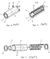
- FIG. 1a shows the view of an electric heater seen obliquely from above.
- the electric heater 10 has an inner metal tube 3 and an outer metal tube 4, which are arranged concentrically one inside the other and are the same length. Furthermore, one sees the ends of a tubular heating element 1, which, as in Figures 1b and 1c is clearly seen meandering in the space formed by the inner metal tube 3 and the outer metal tube 4 is arranged. Furthermore, in FIG. 1a an annular optional bottom plate 5 is provided, which may for example consist of metal, mica, plastic or ceramic. Alternatively, a conclusion of the space between the inner metal tube 3 and the outer metal tube 4 by a potting compound, for example, carried out with a silicone rubber, an epoxy resin or a ceramic putty.
- a suitably compacted powder or granulate 2 can, especially if the volume is temporarily kept closed during compaction, for example by the wall of a die, also be self-supporting, so that in the finished electric heating device 10 no closure of the space between the inner metal tube. 3 and outer metal tube 4 is more necessary.
- FIG. 1b shows shows a sectional view of the electric heater 1a , cut along the line B-B '.
- the embedding of the tubular heating element 1 in the powder or granules 2 is best recognized.
- an annular connection-side end plate 6 can be seen, through which the tubular heating element 1 enters or leaves the tubular heating element 1 is guided out of the space between the inner metal tube 3 and the outer metal tube 4.
- the end plate 6 is optional for the reasons already outlined above, it may consist of the same materials as the bottom plate.
- FIG. 1C shows an exploded view of the electric heater 10 from FIG. 1a neglecting the powder or granules 2, not shown.
- the inner metal tube 3 is inserted into the outer metal tube 4.
- the bottom plate 5 is connected to both metal pipes, eg glued or welded.
- the tubular heating element 1 is inserted between the inner metal pipe 3 and the outer metal pipe 5. Then, the volume between these tubes, preferably with shaking, filled with the powder or granules 2 and the terminal-side end plates 6 are placed and connected to the inner metal tube 3 and outer metal tube 4. Subsequently, the entire arrangement can be compacted.
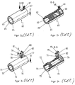
- FIG. 2a shows an embodiment of the invention in an embodiment with a continuous recess in the axial direction.
- the electric heater 20 has an inner metal tube 13 and an outer metal tube 14 concentrically nested and of equal length.
- both the inner metal tube 13 and the outer metal tube 14 are penetrated by a through the two metal tubes 13,14 along its entire axial extent passing through recess 18.
- the inner metal tube 53 and the outer metal tube 54 are connected to each other at the axially oriented edges of the recess 58 by end faces 16,17.
- FIG. 2a again an optional, also slotted bottom plate 15 is provided, for example, made of metal, Mica, plastic or ceramic can exist. Also not shown is the embedding of the tubular heating element 11 in the powder or granules.
- the embodiment according to FIG. 2a can be made in particular by forming a surface heating element, which is a particularly favorable production method.
- FIGS. 2b and 2c show further possibilities for the connection of the tubular heating element 1 of the electric heating device FIG. 1a .
- a connector 9 is provided, which makes the radially through the recess 21 out of the space between the inner metal tube 3 and the outer metal tube 4 outgoing tubular heating element contacted.
- Figure 2c also shows a radial guidance of the tubular heating element 1 through two recesses 22,23.
- FIGS. 2d to 2f show two variants of an electric heater of the invention, in particular, such as FIG. 2e can be seen, a coiled tubular heating element 31 has.
- FIG. 2d shows the view of the electric heater seen obliquely from above.
- the electric heater 30 has an inner metal tube 33 and an outer metal tube 34 concentrically nested and of equal length. Further, one sees the ends of a tubular heating element 31, which, as in FIGS. 2e is more clearly seen coiled arranged in the space formed by the inner metal tube 33 and the outer metal tube 34. Furthermore, an optional bottom plate 35 is again provided in FIG. 2d.
- the outer metal tube 34 has an elongate recess 35 through which the tubular heating element 31 is guided into and out of the space between the inner metal tube 33 and the outer metal tube 34.
- Figure 2e shows a sectional view of the embodiment Figure 2d , cut along the line B-B '.
- Figure 2e shows a sectional view of the embodiment Figure 2d , cut along the line B-B '.
- tubular heating element 31 is guided closer to the center of the longitudinal extension of the outer metal tube 33 through the wall thereof. This is done by an elongated recess, which is then closed with the coverslip 24 and for this reason in FIG. 2f is not recognizable.
- Fig.2g shows the view of an electric heater seen obliquely from above.
- the electric heater 60 has an inner metal tube 63 and an outer metal tube 64 concentrically nested and of equal length. Furthermore, one sees the ends of a tubular heating element 61, which, as in FIGS. 2e is more clearly seen coiled in the space formed by the inner metal tube 63 and the outer metal tube 64 is disposed. Also coiled, further runs a thermocouple 68. Further, in Figure 2g again an optional bottom plate 65 is provided.
- the outer metal tube 64 has an elongated recess 67 through which the tubular heating element 61 and the thermocouple 68 are guided into and out of the space between the inner metal tube 63 and the outer metal tube 64.
- Fig.2h shows a sectional view of the electric heater Fig.2g , cut along the line B-B '.
- the embedding of the tubular heating element 61 in the powder or granulate 62 is best recognized in this illustration.
- an optional terminal-side end plate 66 can be seen.
- Fig.2i shows the view of an electric heater seen obliquely from above.
- the electric heater 70 has an inner metal tube 73 and an outer metal tube 74 concentrically nested and of equal length. Furthermore, one sees the ends of a first tubular Heating element 71, and a second tubular heating element 82 provided with connection plugs 79 and 80, and the end of a thermocouple 78 provided with the connection plug 81.
- the tubular heating elements 71, 82 and the thermocouple 78 are, as in FIG Figures 2k is more clearly seen coiled arranged in the space formed by the inner metal tube 73 and the outer metal tube 74. Further, also in FIG. 2i an optional bottom plate 75 is provided.
- the outer metal tube 74 has an elongated recess 77 through which the tubular heating elements 71, 82 and the thermocouple 81 are guided into and out of the space between the inner metal tube 73 and the outer metal tube 74.
- Fig.2h shows a sectional view of the electric heater Fig.2g , cut along the line B-B '.
- the embedding of the tubular heating elements 71, 82 in the powder or granules 72 is best recognized in this illustration.
- An optional terminal-side end disk 76 is also recognizable.
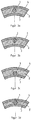
- FIGS. 3a to 3g make use of the electric heater FIG. 1a
- the heating element 1 is always completely either of powder or granules 2 or powder or granules 2 and inner metal tube 3 and / or outer metal tube 4 surrounded.
- FIG. 3b and 3e it has direct contact with the outer metal tube 4, in Figure 3c and 3f direct contact with the inner metal tube 3 and in 3d figure and 3g direct contact with the inner metal tube 3 and the outer metal tube 4.
- the tubular heating element 1 is surrounded only by powder or granules 2.
- FIGS. 3b and 3e . 3c and 3f and 3d and 3g directly shows, when a contact between the tubular heating element 1 and the inner metal tube. 3 and / or the outer metal tube 4 is present, this by a section-wise planar abutment of the tubular heating element 1 to the unchanged profile of the respective metal tube 3,4, but also be prepared by a partial partial embedding of the tubular heating element 1 in the respective metal tube 3.4.
- the illustrated variants represent two extremes, intermediate forms are also conceivable. In particular, a point or line-shaped contact between tubular heating element 1 and the inner metal tube 3 and / or the outer metal tube 4 is conceivable.
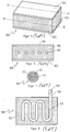
- FIG. 4a shows a sectional view of an embodiment of the invention, corresponding to a section through the cylindrical body of the electric heater along the in FIG. 1a represented line A-A '.
- the electric heater 50 also has a meandering tubular heating element 51 disposed between the inner metal tube 53 and the outer metal tube 54.
- This embodiment is characterized in that the inner metal tube 53 is penetrated by a recess 58 extending over the entire axial extension and thus the entire length of the metal tube.
- end surfaces 56 and 57 are provided according to the invention, which connect the inner metal tube 53 and the outer metal tube 54 to each other at the edges oriented in the axial direction of the recess 58.
- the resulting chamber is filled with powder or granules 52, in which the tubular heating element 51 is embedded.
- This embodiment is particularly useful when a radially asymmetric heating of the component to be heated is necessary, since a desired orientation of this embodiment can easily be predetermined by a ridge provided on this.
- FIG. 4b shows a sectional view of another embodiment of the invention, corresponding to a section through the cylindrical body of the electric heater along the in FIG. 1a represented line A-A '.
- the electric heater 40 also has a meandering shape penetrating tubular heating element 41, which is arranged between the inner metal tube 43 and the outer metal tube 44.
- This embodiment is characterized in that the outer metal tube 44 is penetrated by a recess 48 extending over the entire axial extension and thus the entire length of the metal tube.
- end surfaces 46 and 47 are provided according to the invention, which connect the inner metal tube 43 and the outer metal tube 44 to one another at the edges of the recess 48 which are oriented in the axial direction.
- the resulting chamber is filled with powder or granules 52, in which the tubular heating element 41 is embedded. This embodiment is particularly useful when concealed routing of cables or utility lines is desired.
- FIG. 5 shows an electric heater 100 in one embodiment as a surface heating element with a first metal plate 103 and a second metal plate 104 as boundary surfaces.
- a tubular heating element 101 is arranged in the space between the first metal plate 103 and the second metal plate 104, as in FIG. 6 to recognize a tubular heating element 101 is arranged, but in FIG. 5 can not be seen there, as in FIG. 8 becomes clear, only its connection portion 106 protrudes with connector 109 from the electric heater 100 and this is on the side facing away from the viewer.
- the tubular heating element 101 is embedded in a powder or granules 102 filling the space between the first metal plate 103 and the second metal plate 104. In the embodiment illustrated here, no frame is provided; when the powder or granules 102 is compacted, it is not needed to hold the material in place.
- FIG. 7 shows an enlarged section through the tubular heating element 101, based on which a typical structure of the tubular heating element 101 can be followed.
- the tubular heating element 101 which can be used in this embodiment not only in disciplinncopy comprisen, but also in all other electric heaters and is preferably used, has a heating element 111 which is embedded in a surrounded by a tubular steel jacket 113, central magnesium oxide 112 , In principle, other materials for the jacket and the electrically insulating core are conceivable.
- connection plug 109 In the presentation of the FIG. 8 it can further be seen that the tubular heating element 101 in this case emerges tangentially from the electric heating device 100 with its connection region 106 terminated by the connection plug 109. In principle, another, for example, a normal guidance of the connection region 106 from the electric heating device 100 is also possible.
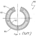
- an electric heating device 100 designed as a surface heating element according to the invention can easily be adapted by deformation to other desired shapes, in this case an almost closed ring body, which can be used, for example, for heating a cylindrical component.
- the first boundary surface and the second boundary surface can be adjusted particularly well with the electric heating device 100 according to the invention.
Landscapes
- Engineering & Computer Science (AREA)
- Mechanical Engineering (AREA)
- General Engineering & Computer Science (AREA)
- Manufacturing & Machinery (AREA)
- Resistance Heating (AREA)
Claims (8)
- Dispositif de chauffage électrique (10, 30, 40, 50, 60, 70, 100) destiné à permettre le chauffage de surfaces d'éléments sur lesquelles est appliqué ou monté le dispositif de chauffage électrique (10, 30, 40, 50, 60, 70, 100), comprenant au moins un élément de chauffage tubulaire (1, 11, 31, 41, 51, 61, 71, 82, 101) qui est muni d'une enveloppe métallique et au moins une surface de limitation, au moins une seconde surface de limitation en métal étant prévue, l'élément de chauffage tubulaire (1, 11, 31, 41, 51, 61, 71, 82, 101) étant positionné entre la première surface de limitation et la seconde surface de limitation en métal, et l'espace compris entre les surfaces de limitation en métal dans laquelle est positionné l'élément de chauffage tubulaire (1, 11, 31, 41, 51, 61, 71, 82, 101) est rempli d'une poudre ou de granulés (2, 32, 42, 52, 62, 72, 102) de sorte que l'élément de chauffage tubulaire (1, 11, 31, 41, 51, 61, 71, 82, 101) soit noyé au moins partiellement dans au moins une poudre ou de granulés (2, 32, 42, 52, 62, 72, 102), la poudre ou les granulés (2, 32, 42, 52, 62, 72, 102) s'appliquant au moins sur des parties d'une surface de limitation, les surfaces de limitation en métal étant formées par des parois d'un tube métallique externe (4, 14, 34, 44, 54, 64, 74) et d'un tube métallique interne (3, 13, 33, 43, 53, 63, 73) situé dans le tube métallique externe (4, 14, 34, 44, 54, 64, 74), caractérisé en ce que
le tube métallique externe (4, 14, 34, 44, 54, 64, 74) et/ou le tube métallique interne (3, 13, 33, 43, 53, 63, 73) comporte(nt) un évidement (18, 21, 22, 23, 48, 58, 67, 77) s'étendant en direction axiale, et les deux surfaces de limitation sont reliées solidairement l'une à l'autre par au moins une autre surface de limitation. - Dispositif de chauffage électrique (10, 30, 40, 50, 60, 70, 100), conforme à la revendication 1,
caractérisé en ce qu'
un perçage interne ou la totalité du dispositif de chauffage électrique (10, 30, 40, 50, 60, 70, 100) a une géométrie ovale, angulaire, courbe, coudée ou elliptique. - Dispositif de chauffage électrique (10, 30, 40, 50, 60, 70, 100), conforme à l'une des revendications précédentes,
caractérisé en ce que
les deux surfaces de limitation en métal sont constituées par l'assemblage de différents segments de tôle ou de tubes en un même matériau ou en des matériaux différents. - Dispositif de chauffage électrique (10, 30, 40, 50, 60, 70, 100), conforme à l'une des revendications précédentes,
caractérisé en ce que
sur l'une ou les deux extrémités des surfaces de limitation tubulaires en métal sont fixés des disques ou des anneaux en métal, en mica, en matériau synthétique ou en céramique. - Dispositif de chauffage électrique (10, 30, 40, 50, 60, 70, 100), conforme à l'une des revendications précédentes,
caractérisé en ce que
l'une ou les deux extrémités des surfaces de limitation tubulaires en métal sont fermées par une masse de coulée, en particulier en caoutchouc au silicone, en résine époxy ou une masse de ciment céramique. - Dispositif de chauffage électrique (10, 30, 40, 50, 60, 70, 100), conforme à l'une des revendications précédentes,
caractérisé en ce que
le dispositif de chauffage électrique (10, 30, 40, 50, 60, 70, 100) est rempli par plusieurs poudres métalliques différentes, en particulier par plusieurs poudres métalliques différentes qui sont situées dans différentes chambres du dispositif de chauffage électrique (10, 30, 40, 50, 60, 70, 100). - Dispositif de chauffage électrique (10, 30, 40, 50, 60, 70, 100), conforme à la revendication 6,
caractérisé en ce que
le tube métallique externe (4, 14, 34, 44, 54, 64, 74) et le tube métallique interne (3, 13, 33, 43, 53, 63, 73) comportent un évidement (18, 21, 22, 23, 48, 58, 67, 77) qui s'étend sur la totalité de leur longueur. - Dispositif de chauffage électrique (10, 30, 40, 50, 60, 70, 100), conforme à la revendication 7,
caractérisé en ce qu'
un thermomètre enveloppe ou un thermo-élément (68, 78) est introduit au travers de l'évidement (18, 21, 22, 23, 48, 58, 67, 77).
Applications Claiming Priority (1)
| Application Number | Priority Date | Filing Date | Title |
|---|---|---|---|
| DE102009040809A DE102009040809A1 (de) | 2009-09-10 | 2009-09-10 | Elektrische Heizvorrichtung und Verfahren zur Herstellung einer elektrischen Heizvorrichtung |
Publications (3)
| Publication Number | Publication Date |
|---|---|
| EP2296433A2 EP2296433A2 (fr) | 2011-03-16 |
| EP2296433A3 EP2296433A3 (fr) | 2011-09-28 |
| EP2296433B1 true EP2296433B1 (fr) | 2016-06-22 |
Family
ID=42115063
Family Applications (1)
| Application Number | Title | Priority Date | Filing Date |
|---|---|---|---|
| EP10009372.3A Active EP2296433B1 (fr) | 2009-09-10 | 2010-09-09 | Dispositif de chauffage électrique et procédé de fabrication d'un dispositif de chauffage électrique |
Country Status (4)
| Country | Link |
|---|---|
| US (1) | US8941034B2 (fr) |
| EP (1) | EP2296433B1 (fr) |
| CN (1) | CN102026431B (fr) |
| DE (2) | DE102009040809A1 (fr) |
Cited By (1)
| Publication number | Priority date | Publication date | Assignee | Title |
|---|---|---|---|---|
| DE202017103387U1 (de) | 2017-06-06 | 2017-07-13 | Türk & Hillinger GmbH | Innenaufbau für eine elektrische Heizvorrichtungung mit zumindest abschnittsweise frei gewendeltem Heizelement und elektrische Heizvorrichtung |
Families Citing this family (24)
| Publication number | Priority date | Publication date | Assignee | Title |
|---|---|---|---|---|
| EP2434195B1 (fr) * | 2010-09-23 | 2013-03-13 | Andreas Massold | Procédé de mesure de température dans un véhicule |
| US9435477B2 (en) * | 2011-03-22 | 2016-09-06 | Sami Mustafa | Creating thermal uniformity in heated piping and weldment systems |
| DE102011075107A1 (de) * | 2011-05-03 | 2012-11-08 | Universität Stuttgart | Vorrichtung zur Temperierung eines Werkzeugs |
| CN102958212A (zh) * | 2011-08-26 | 2013-03-06 | 张振权 | 一种双向导热电热管 |
| EP2839200A4 (fr) * | 2012-04-20 | 2015-07-01 | Graco Minnesota Inc | Tuyau chauffé de manière électrique |
| CN104411218B (zh) * | 2012-05-15 | 2020-07-07 | 布莱克曼两合公司 | 饮料制备装置、流过加热器设备及其生产方法 |
| FR2994593B1 (fr) * | 2012-08-20 | 2014-09-05 | Technip France | Raccord intermediaire de connexion d'elements de conduite rigide de transport de fluide, reseau de conduites et procede d'assemblage associes |
| DE102012109740B4 (de) | 2012-10-12 | 2018-04-05 | Türk & Hillinger GmbH | Elektrische Heizvorrichtung und Verfahren zur Herstellung einer solchen elektrischen Heizvorrichtung |
| DE102013102378A1 (de) * | 2013-03-11 | 2014-09-11 | GC-heat Gebhard GmbH & Co.KG | Heizeinrichtung zum außenseitigen Beheizen eines rohrförmigen Bauteiles |
| US10117292B2 (en) * | 2013-04-19 | 2018-10-30 | Chromalox, Inc. | Medium voltage heater elements moisture detection circuit |
| DE102013212205B4 (de) * | 2013-06-26 | 2024-02-08 | Türk & Hillinger GmbH | Verfahren zur Herstellung einer elektrischen Heizpatrone |
| WO2015186872A1 (fr) * | 2014-06-02 | 2015-12-10 | 우진공업주식회사 | Dispositif de chauffage pour thermostat électronique et son procédé de fabrication |
| DE102015114886B4 (de) * | 2015-09-04 | 2022-05-12 | Türk & Hillinger GmbH | Verfahren zur Herstellung einer Heizvorrichtung für Fluide |
| US10792698B2 (en) * | 2015-10-29 | 2020-10-06 | Warren Environmental & Coating, Llc | Heated epoxy cartridges |
| CN205962842U (zh) * | 2016-07-29 | 2017-02-22 | 深圳市合元科技有限公司 | 用于电子烟的加热装置及电子烟雾化器 |
| CN106455164A (zh) * | 2016-08-31 | 2017-02-22 | 迈为医疗技术(深圳)有限公司 | 一种稳定反馈封装加热轮 |
| DE102017222367B4 (de) | 2017-12-11 | 2024-05-02 | EFI Solutions GmbH | Verfahren zum Herstellen eines Flächenheizelementes |
| DE202018101632U1 (de) | 2018-03-23 | 2018-04-03 | Türk & Hillinger GmbH | Elektrische Heizvorrichtung zur Beheizung eines Körpers und System aus einer Vorrichtung mit einem zu beheizenden Körper und einer elektrischen Heizvorrichtung zur Beheizung des zu beheizenden Körpers |
| DE102018131766B3 (de) | 2018-12-11 | 2020-03-26 | Stego-Holding Gmbh | Haltekörper, Heizgerät und Verfahren |
| US11946583B1 (en) * | 2020-03-18 | 2024-04-02 | Durex International Corp. | Flexible conforming silicone rubber heater for complex geometry fluid lines and method |
| CN113892702B (zh) * | 2021-08-26 | 2023-11-03 | 深圳市基克纳科技有限公司 | 一种外壳导电型发热体的制作方法 |
| CN114932631B (zh) * | 2022-04-18 | 2023-05-30 | 湖南工学院 | 一种聚羧酸减水剂的自动加料装置 |
| CN115583056B (zh) * | 2022-10-17 | 2026-02-03 | 公元管道(安徽)有限公司 | 一种纤维复合管成型设备的加热结构 |
| CN115978339B (zh) * | 2022-10-18 | 2024-06-14 | 彭军 | 一种带温控装置的电加热软管 |
Family Cites Families (27)
| Publication number | Priority date | Publication date | Assignee | Title |
|---|---|---|---|---|
| US1674488A (en) * | 1922-12-20 | 1928-06-19 | Gen Electric | Electric heating unit |
| GB1028398A (en) | 1964-05-26 | 1966-05-04 | Ass Elect Ind | Improvements in electric heater arrangements |
| US3519023A (en) * | 1968-08-05 | 1970-07-07 | Ora W Burns Sr | Defrosting collar for pipes |
| DE7110931U (de) | 1971-03-23 | 1971-11-25 | Schmitz F | Vorgefertigte panzerplatte fuer kohle- und gesteinsmuehle |
| DE7225341U (de) | 1972-07-07 | 1977-01-27 | Tuerk & Hillinger Kg, 7200 Tuttlingen | Elektrischer flachheizkoerper |
| CA1097472A (fr) | 1976-07-16 | 1981-03-17 | Walter R. Crandell | Buse chauffee a l'electricite et methode de production |
| US4080726A (en) * | 1977-02-23 | 1978-03-28 | Siemens Aktiengesellschaft | Method for manufacturing an electrical heating device |
| DE2816076A1 (de) * | 1978-04-13 | 1979-10-25 | Siemens Ag | Heizer mit ferroelektrischem keramik-heizelement |
| SE444357B (sv) | 1980-01-14 | 1986-04-07 | Forsheda Gummifabrik Ab | Sett for formning av en rormuff |
| DE3243780A1 (de) | 1982-11-26 | 1984-05-30 | Wolff, Hans-Martin, 6101 Messel | Heizkoerper und verfahren zu seiner herstellung |
| DE3505517C1 (de) | 1985-02-18 | 1986-09-04 | Türk & Hillinger GmbH, 7200 Tuttlingen | Elektrische Heizeinrichtung, insbesondere für Kunststoff-Spritzdüsen |
| DE8620956U1 (de) | 1986-08-05 | 1986-11-27 | Jetform Heißkanalnormalien und Zubehör GmbH, 7255 Rutesheim | Vorrichtung zur elektrischen Beheizung von Heißkanaldüsen |
| DE8800261U1 (de) * | 1988-01-12 | 1988-02-25 | Elpag Ag Chur, Chur | Rohrheizkörperendenabschluß |
| DE4224101A1 (de) | 1991-07-25 | 1993-01-28 | Barmag Barmer Maschf | Heizschiene |
| US5453599A (en) * | 1994-02-14 | 1995-09-26 | Hoskins Manufacturing Company | Tubular heating element with insulating core |
| FR2731237B1 (fr) * | 1995-03-02 | 1997-04-30 | Seb Sa | Structure chauffante, notamment pour appareil electromenager realise selon une structure sandwich et appareil electromenager comportant une telle structure chauffante |
| DE19943192A1 (de) | 1999-09-09 | 2001-04-05 | Hotset Heizpatronen Zubehoer | Rohrförmiges Heizelement |
| DE20015016U1 (de) | 2000-06-14 | 2000-12-14 | Keller, Ihne & Tesch KG, 68623 Lampertheim | Rohrheizpatrone |
| DE20108963U1 (de) | 2001-05-29 | 2001-08-16 | Türk & Hillinger GmbH, 78532 Tuttlingen | Elektrischer Flachheizkörper |
| DE20109413U1 (de) * | 2001-06-06 | 2001-08-23 | Türk & Hillinger GmbH, 78532 Tuttlingen | Elektrische Heizeinrichtung für zylindrische Körper |
| DE20118050U1 (de) | 2001-11-06 | 2002-01-24 | Türk & Hillinger GmbH, 78532 Tuttlingen | Elektrischer Flachheizkörper |
| DE20212918U1 (de) | 2002-08-22 | 2002-10-17 | Türk & Hillinger GmbH, 78532 Tuttlingen | Elektrische Heizeinrichtung für zylindrische Körper |
| DE20215960U1 (de) | 2002-09-13 | 2003-01-16 | Türk & Hillinger GmbH, 78532 Tuttlingen | Elektrische Heizpatrone für zylindrische Körper |
| US6782922B1 (en) * | 2003-05-30 | 2004-08-31 | John Manville International, Inc. | Coated fibrous pipe insulation system |
| CN2905085Y (zh) | 2005-12-23 | 2007-05-30 | 常州市武进华福纺织有限公司 | 流体调温加热器 |
| DE202007010865U1 (de) * | 2007-08-03 | 2007-10-11 | Türk & Hillinger GmbH | Elektrische Heizpatrone |
| DE202008016439U1 (de) | 2008-12-11 | 2009-03-12 | Türk & Hillinger GmbH | Heizpatrone |
-
2009
- 2009-09-10 DE DE102009040809A patent/DE102009040809A1/de not_active Ceased
-
2010
- 2010-01-29 DE DE202010001576U patent/DE202010001576U1/de not_active Expired - Lifetime
- 2010-09-09 EP EP10009372.3A patent/EP2296433B1/fr active Active
- 2010-09-09 US US12/878,222 patent/US8941034B2/en active Active
- 2010-09-10 CN CN201010283500.2A patent/CN102026431B/zh active Active
Cited By (4)
| Publication number | Priority date | Publication date | Assignee | Title |
|---|---|---|---|---|
| DE202017103387U1 (de) | 2017-06-06 | 2017-07-13 | Türk & Hillinger GmbH | Innenaufbau für eine elektrische Heizvorrichtungung mit zumindest abschnittsweise frei gewendeltem Heizelement und elektrische Heizvorrichtung |
| DE102018110272A1 (de) | 2017-06-06 | 2018-12-06 | Türk & Hillinger GmbH | Innenaufbau für eine elektrische Heizvorrichtung mit zumindest abschnittsweise frei gewendeltem Heizelement und elektrische Heizvorrichtung |
| US10880957B2 (en) | 2017-06-06 | 2020-12-29 | Türk & Hillinger GmbH | Internal structure for an electrical heating device with heating element freely coiled at least in sections and electrical heating device |
| DE102018110272B4 (de) | 2017-06-06 | 2024-09-05 | Türk & Hillinger GmbH | Innenaufbau für eine elektrische Heizvorrichtung mit zumindest abschnittsweise frei gewendeltem Heizelement und elektrische Heizvorrichtung |
Also Published As
| Publication number | Publication date |
|---|---|
| CN102026431A (zh) | 2011-04-20 |
| EP2296433A2 (fr) | 2011-03-16 |
| US20110056931A1 (en) | 2011-03-10 |
| US8941034B2 (en) | 2015-01-27 |
| DE202010001576U1 (de) | 2010-04-22 |
| EP2296433A3 (fr) | 2011-09-28 |
| CN102026431B (zh) | 2014-12-31 |
| DE102009040809A1 (de) | 2011-03-24 |
Similar Documents
| Publication | Publication Date | Title |
|---|---|---|
| EP2296433A2 (fr) | Dispositif de chauffage électrique et procédé de fabrication d'un dispositif de chauffage électrique | |
| DE102013212205B4 (de) | Verfahren zur Herstellung einer elektrischen Heizpatrone | |
| DE3153393C2 (fr) | ||
| DE102011012770A1 (de) | Hochleistungs-Durchlauferhitzer | |
| EP1916873B1 (fr) | Elément générateur de la chaleur pour un dispositif chauffant électrique et son procédé de fabrication | |
| DE102015114886B4 (de) | Verfahren zur Herstellung einer Heizvorrichtung für Fluide | |
| EP2180759B1 (fr) | Dispositif de chauffage électrique | |
| EP2355614B1 (fr) | Dispositif de chauffage électrique et procédé de fabrication d'un dispositif de chauffage électrique | |
| DE102012109740B4 (de) | Elektrische Heizvorrichtung und Verfahren zur Herstellung einer solchen elektrischen Heizvorrichtung | |
| DE2804749B2 (de) | Durchlauferhitzer | |
| WO2019233912A1 (fr) | Conducteur multibrin, dispositif d'enroulement et procédé de fabrication | |
| EP3361573A1 (fr) | Procédé de raccordement d'un dispositif électrique à un câble de raccordement et dispositif électrique pourvue d'un câble de raccordement | |
| WO1979001018A1 (fr) | Manchon a souder en matiere thermoplastique | |
| CH653419A5 (de) | Verbindungsvorrichtung zum verbinden laenglicher teile und zugehoeriges verwendungsverfahren. | |
| EP2353837B1 (fr) | Dispositif de chauffage électrique doté d'un tuyau oméga | |
| DE102010006356B4 (de) | Elektrische Heizvorrichtung und Verfahren zur Herstellung einer elektrischen Heizvorrichtung | |
| EP3519785B1 (fr) | Câble, dispositif de mesure de température et procédé de fabrication d'un câble | |
| EP3993562B1 (fr) | Cartouche chauffante comportant une pâte de remplissage céramique | |
| EP1037507A2 (fr) | Procédé de fabrication d'éléments électriques chauffants dans un moule à injection | |
| DE102019107155B4 (de) | Verfahren zur Herstellung einer elektrischen Heizvorrichtung | |
| DE102012103559B4 (de) | Flüssigkeitsheizung | |
| EP3023039A1 (fr) | Corps de chauffage, chauffe-eau instantané pour machines à boissons chaudes et son procédé de fabrication | |
| DE102018109306A1 (de) | Verfahren zur Herstellung einer elektrischen Heizvorrichtung | |
| EP0670209A1 (fr) | Dispositif de chauffage, notamment à utiliser dans des moules d'injection pour traiter des matières thermoplastiques | |
| EP2127786B1 (fr) | Corps de chauffage pour milieux d'écoulement et son procédé de fabrication |
Legal Events
| Date | Code | Title | Description |
|---|---|---|---|
| PUAI | Public reference made under article 153(3) epc to a published international application that has entered the european phase |
Free format text: ORIGINAL CODE: 0009012 |
|
| AK | Designated contracting states |
Kind code of ref document: A2 Designated state(s): AL AT BE BG CH CY CZ DE DK EE ES FI FR GB GR HR HU IE IS IT LI LT LU LV MC MK MT NL NO PL PT RO SE SI SK SM TR |
|
| AX | Request for extension of the european patent |
Extension state: BA ME RS |
|
| PUAL | Search report despatched |
Free format text: ORIGINAL CODE: 0009013 |
|
| AK | Designated contracting states |
Kind code of ref document: A3 Designated state(s): AL AT BE BG CH CY CZ DE DK EE ES FI FR GB GR HR HU IE IS IT LI LT LU LV MC MK MT NL NO PL PT RO SE SI SK SM TR |
|
| AX | Request for extension of the european patent |
Extension state: BA ME RS |
|
| RIC1 | Information provided on ipc code assigned before grant |
Ipc: H05B 3/58 20060101ALI20110824BHEP Ipc: H05B 3/48 20060101AFI20110824BHEP |
|
| 17P | Request for examination filed |
Effective date: 20120328 |
|
| REG | Reference to a national code |
Ref country code: DE Ref legal event code: R079 Ref document number: 502010011857 Country of ref document: DE Free format text: PREVIOUS MAIN CLASS: H05B0003580000 Ipc: H05B0003480000 |
|
| GRAP | Despatch of communication of intention to grant a patent |
Free format text: ORIGINAL CODE: EPIDOSNIGR1 |
|
| RIC1 | Information provided on ipc code assigned before grant |
Ipc: H05B 3/48 20060101AFI20151013BHEP Ipc: H05B 3/58 20060101ALI20151013BHEP |
|
| INTG | Intention to grant announced |
Effective date: 20151104 |
|
| RAP1 | Party data changed (applicant data changed or rights of an application transferred) |
Owner name: TURK & HILLINGER GMBH |
|
| GRAS | Grant fee paid |
Free format text: ORIGINAL CODE: EPIDOSNIGR3 |
|
| INTG | Intention to grant announced |
Effective date: 20160304 |
|
| GRAA | (expected) grant |
Free format text: ORIGINAL CODE: 0009210 |
|
| AK | Designated contracting states |
Kind code of ref document: B1 Designated state(s): AL AT BE BG CH CY CZ DE DK EE ES FI FR GB GR HR HU IE IS IT LI LT LU LV MC MK MT NL NO PL PT RO SE SI SK SM TR |
|
| REG | Reference to a national code |
Ref country code: GB Ref legal event code: FG4D Free format text: NOT ENGLISH |
|
| REG | Reference to a national code |
Ref country code: CH Ref legal event code: NV Representative=s name: R.A. EGLI AND CO, PATENTANWAELTE, CH Ref country code: CH Ref legal event code: EP |
|
| REG | Reference to a national code |
Ref country code: IE Ref legal event code: FG4D Free format text: LANGUAGE OF EP DOCUMENT: GERMAN |
|
| REG | Reference to a national code |
Ref country code: AT Ref legal event code: REF Ref document number: 808308 Country of ref document: AT Kind code of ref document: T Effective date: 20160715 |
|
| REG | Reference to a national code |
Ref country code: DE Ref legal event code: R096 Ref document number: 502010011857 Country of ref document: DE |
|
| REG | Reference to a national code |
Ref country code: LT Ref legal event code: MG4D |
|
| REG | Reference to a national code |
Ref country code: NL Ref legal event code: MP Effective date: 20160622 |
|
| PG25 | Lapsed in a contracting state [announced via postgrant information from national office to epo] |
Ref country code: NO Free format text: LAPSE BECAUSE OF FAILURE TO SUBMIT A TRANSLATION OF THE DESCRIPTION OR TO PAY THE FEE WITHIN THE PRESCRIBED TIME-LIMIT Effective date: 20160922 Ref country code: FI Free format text: LAPSE BECAUSE OF FAILURE TO SUBMIT A TRANSLATION OF THE DESCRIPTION OR TO PAY THE FEE WITHIN THE PRESCRIBED TIME-LIMIT Effective date: 20160622 Ref country code: LT Free format text: LAPSE BECAUSE OF FAILURE TO SUBMIT A TRANSLATION OF THE DESCRIPTION OR TO PAY THE FEE WITHIN THE PRESCRIBED TIME-LIMIT Effective date: 20160622 |
|
| PG25 | Lapsed in a contracting state [announced via postgrant information from national office to epo] |
Ref country code: GR Free format text: LAPSE BECAUSE OF FAILURE TO SUBMIT A TRANSLATION OF THE DESCRIPTION OR TO PAY THE FEE WITHIN THE PRESCRIBED TIME-LIMIT Effective date: 20160923 Ref country code: HR Free format text: LAPSE BECAUSE OF FAILURE TO SUBMIT A TRANSLATION OF THE DESCRIPTION OR TO PAY THE FEE WITHIN THE PRESCRIBED TIME-LIMIT Effective date: 20160622 Ref country code: NL Free format text: LAPSE BECAUSE OF FAILURE TO SUBMIT A TRANSLATION OF THE DESCRIPTION OR TO PAY THE FEE WITHIN THE PRESCRIBED TIME-LIMIT Effective date: 20160622 Ref country code: SE Free format text: LAPSE BECAUSE OF FAILURE TO SUBMIT A TRANSLATION OF THE DESCRIPTION OR TO PAY THE FEE WITHIN THE PRESCRIBED TIME-LIMIT Effective date: 20160622 Ref country code: LV Free format text: LAPSE BECAUSE OF FAILURE TO SUBMIT A TRANSLATION OF THE DESCRIPTION OR TO PAY THE FEE WITHIN THE PRESCRIBED TIME-LIMIT Effective date: 20160622 |
|
| PG25 | Lapsed in a contracting state [announced via postgrant information from national office to epo] |
Ref country code: RO Free format text: LAPSE BECAUSE OF FAILURE TO SUBMIT A TRANSLATION OF THE DESCRIPTION OR TO PAY THE FEE WITHIN THE PRESCRIBED TIME-LIMIT Effective date: 20160622 Ref country code: EE Free format text: LAPSE BECAUSE OF FAILURE TO SUBMIT A TRANSLATION OF THE DESCRIPTION OR TO PAY THE FEE WITHIN THE PRESCRIBED TIME-LIMIT Effective date: 20160622 Ref country code: SK Free format text: LAPSE BECAUSE OF FAILURE TO SUBMIT A TRANSLATION OF THE DESCRIPTION OR TO PAY THE FEE WITHIN THE PRESCRIBED TIME-LIMIT Effective date: 20160622 Ref country code: IS Free format text: LAPSE BECAUSE OF FAILURE TO SUBMIT A TRANSLATION OF THE DESCRIPTION OR TO PAY THE FEE WITHIN THE PRESCRIBED TIME-LIMIT Effective date: 20161022 Ref country code: CZ Free format text: LAPSE BECAUSE OF FAILURE TO SUBMIT A TRANSLATION OF THE DESCRIPTION OR TO PAY THE FEE WITHIN THE PRESCRIBED TIME-LIMIT Effective date: 20160622 |
|
| PG25 | Lapsed in a contracting state [announced via postgrant information from national office to epo] |
Ref country code: PT Free format text: LAPSE BECAUSE OF FAILURE TO SUBMIT A TRANSLATION OF THE DESCRIPTION OR TO PAY THE FEE WITHIN THE PRESCRIBED TIME-LIMIT Effective date: 20161024 Ref country code: ES Free format text: LAPSE BECAUSE OF FAILURE TO SUBMIT A TRANSLATION OF THE DESCRIPTION OR TO PAY THE FEE WITHIN THE PRESCRIBED TIME-LIMIT Effective date: 20160622 Ref country code: BE Free format text: LAPSE BECAUSE OF NON-PAYMENT OF DUE FEES Effective date: 20160930 Ref country code: PL Free format text: LAPSE BECAUSE OF FAILURE TO SUBMIT A TRANSLATION OF THE DESCRIPTION OR TO PAY THE FEE WITHIN THE PRESCRIBED TIME-LIMIT Effective date: 20160622 Ref country code: SM Free format text: LAPSE BECAUSE OF FAILURE TO SUBMIT A TRANSLATION OF THE DESCRIPTION OR TO PAY THE FEE WITHIN THE PRESCRIBED TIME-LIMIT Effective date: 20160622 |
|
| REG | Reference to a national code |
Ref country code: DE Ref legal event code: R097 Ref document number: 502010011857 Country of ref document: DE |
|
| PG25 | Lapsed in a contracting state [announced via postgrant information from national office to epo] |
Ref country code: MC Free format text: LAPSE BECAUSE OF FAILURE TO SUBMIT A TRANSLATION OF THE DESCRIPTION OR TO PAY THE FEE WITHIN THE PRESCRIBED TIME-LIMIT Effective date: 20160622 |
|
| PLBE | No opposition filed within time limit |
Free format text: ORIGINAL CODE: 0009261 |
|
| STAA | Information on the status of an ep patent application or granted ep patent |
Free format text: STATUS: NO OPPOSITION FILED WITHIN TIME LIMIT |
|
| GBPC | Gb: european patent ceased through non-payment of renewal fee |
Effective date: 20160922 |
|
| 26N | No opposition filed |
Effective date: 20170323 |
|
| PG25 | Lapsed in a contracting state [announced via postgrant information from national office to epo] |
Ref country code: DK Free format text: LAPSE BECAUSE OF FAILURE TO SUBMIT A TRANSLATION OF THE DESCRIPTION OR TO PAY THE FEE WITHIN THE PRESCRIBED TIME-LIMIT Effective date: 20160622 |
|
| REG | Reference to a national code |
Ref country code: IE Ref legal event code: MM4A |
|
| REG | Reference to a national code |
Ref country code: FR Ref legal event code: ST Effective date: 20170531 |
|
| PG25 | Lapsed in a contracting state [announced via postgrant information from national office to epo] |
Ref country code: GB Free format text: LAPSE BECAUSE OF NON-PAYMENT OF DUE FEES Effective date: 20160922 Ref country code: FR Free format text: LAPSE BECAUSE OF NON-PAYMENT OF DUE FEES Effective date: 20160930 Ref country code: IE Free format text: LAPSE BECAUSE OF NON-PAYMENT OF DUE FEES Effective date: 20160909 |
|
| PG25 | Lapsed in a contracting state [announced via postgrant information from national office to epo] |
Ref country code: LU Free format text: LAPSE BECAUSE OF NON-PAYMENT OF DUE FEES Effective date: 20160909 Ref country code: SI Free format text: LAPSE BECAUSE OF FAILURE TO SUBMIT A TRANSLATION OF THE DESCRIPTION OR TO PAY THE FEE WITHIN THE PRESCRIBED TIME-LIMIT Effective date: 20160622 |
|
| REG | Reference to a national code |
Ref country code: AT Ref legal event code: MM01 Ref document number: 808308 Country of ref document: AT Kind code of ref document: T Effective date: 20160909 |
|
| REG | Reference to a national code |
Ref country code: BE Ref legal event code: MM Effective date: 20160930 |
|
| PG25 | Lapsed in a contracting state [announced via postgrant information from national office to epo] |
Ref country code: AT Free format text: LAPSE BECAUSE OF NON-PAYMENT OF DUE FEES Effective date: 20160909 |
|
| PG25 | Lapsed in a contracting state [announced via postgrant information from national office to epo] |
Ref country code: CY Free format text: LAPSE BECAUSE OF FAILURE TO SUBMIT A TRANSLATION OF THE DESCRIPTION OR TO PAY THE FEE WITHIN THE PRESCRIBED TIME-LIMIT Effective date: 20160622 Ref country code: HU Free format text: LAPSE BECAUSE OF FAILURE TO SUBMIT A TRANSLATION OF THE DESCRIPTION OR TO PAY THE FEE WITHIN THE PRESCRIBED TIME-LIMIT; INVALID AB INITIO Effective date: 20100909 |
|
| PG25 | Lapsed in a contracting state [announced via postgrant information from national office to epo] |
Ref country code: MT Free format text: LAPSE BECAUSE OF FAILURE TO SUBMIT A TRANSLATION OF THE DESCRIPTION OR TO PAY THE FEE WITHIN THE PRESCRIBED TIME-LIMIT Effective date: 20160622 Ref country code: TR Free format text: LAPSE BECAUSE OF FAILURE TO SUBMIT A TRANSLATION OF THE DESCRIPTION OR TO PAY THE FEE WITHIN THE PRESCRIBED TIME-LIMIT Effective date: 20160622 Ref country code: MK Free format text: LAPSE BECAUSE OF FAILURE TO SUBMIT A TRANSLATION OF THE DESCRIPTION OR TO PAY THE FEE WITHIN THE PRESCRIBED TIME-LIMIT Effective date: 20160622 |
|
| PG25 | Lapsed in a contracting state [announced via postgrant information from national office to epo] |
Ref country code: BG Free format text: LAPSE BECAUSE OF FAILURE TO SUBMIT A TRANSLATION OF THE DESCRIPTION OR TO PAY THE FEE WITHIN THE PRESCRIBED TIME-LIMIT Effective date: 20160622 |
|
| PG25 | Lapsed in a contracting state [announced via postgrant information from national office to epo] |
Ref country code: AL Free format text: LAPSE BECAUSE OF FAILURE TO SUBMIT A TRANSLATION OF THE DESCRIPTION OR TO PAY THE FEE WITHIN THE PRESCRIBED TIME-LIMIT Effective date: 20160622 |
|
| REG | Reference to a national code |
Ref country code: CH Ref legal event code: U11 Free format text: ST27 STATUS EVENT CODE: U-0-0-U10-U11 (AS PROVIDED BY THE NATIONAL OFFICE) Effective date: 20251001 |
|
| PGFP | Annual fee paid to national office [announced via postgrant information from national office to epo] |
Ref country code: DE Payment date: 20251028 Year of fee payment: 16 |
|
| PGFP | Annual fee paid to national office [announced via postgrant information from national office to epo] |
Ref country code: IT Payment date: 20250930 Year of fee payment: 16 |
|
| PGFP | Annual fee paid to national office [announced via postgrant information from national office to epo] |
Ref country code: CH Payment date: 20251001 Year of fee payment: 16 |