EP2296446A1 - Vorschaltgerät für Leuchtstofflampen - Google Patents
Vorschaltgerät für Leuchtstofflampen Download PDFInfo
- Publication number
- EP2296446A1 EP2296446A1 EP20100425211 EP10425211A EP2296446A1 EP 2296446 A1 EP2296446 A1 EP 2296446A1 EP 20100425211 EP20100425211 EP 20100425211 EP 10425211 A EP10425211 A EP 10425211A EP 2296446 A1 EP2296446 A1 EP 2296446A1
- Authority
- EP
- European Patent Office
- Prior art keywords
- control circuit
- tubes
- power
- voltage
- microcontroller
- Prior art date
- Legal status (The legal status is an assumption and is not a legal conclusion. Google has not performed a legal analysis and makes no representation as to the accuracy of the status listed.)
- Ceased
Links
- 238000004891 communication Methods 0.000 claims abstract description 14
- 239000013256 coordination polymer Substances 0.000 claims abstract description 13
- 238000001914 filtration Methods 0.000 claims abstract description 12
- 230000007613 environmental effect Effects 0.000 claims abstract description 7
- 238000005259 measurement Methods 0.000 claims abstract description 3
- 238000000034 method Methods 0.000 claims description 24
- 230000008569 process Effects 0.000 claims description 24
- 230000005540 biological transmission Effects 0.000 claims description 11
- 238000005070 sampling Methods 0.000 claims description 11
- 238000001514 detection method Methods 0.000 claims description 9
- 238000007514 turning Methods 0.000 claims description 8
- 238000010438 heat treatment Methods 0.000 claims description 7
- 238000012360 testing method Methods 0.000 claims description 6
- 238000004364 calculation method Methods 0.000 claims description 4
- 238000013480 data collection Methods 0.000 claims description 2
- 238000012544 monitoring process Methods 0.000 claims description 2
- 238000012552 review Methods 0.000 claims 1
- 239000003990 capacitor Substances 0.000 description 17
- 230000006870 function Effects 0.000 description 10
- 238000010586 diagram Methods 0.000 description 9
- 238000004458 analytical method Methods 0.000 description 7
- 238000004804 winding Methods 0.000 description 5
- PZNPLUBHRSSFHT-RRHRGVEJSA-N 1-hexadecanoyl-2-octadecanoyl-sn-glycero-3-phosphocholine Chemical compound CCCCCCCCCCCCCCCCCC(=O)O[C@@H](COP([O-])(=O)OCC[N+](C)(C)C)COC(=O)CCCCCCCCCCCCCCC PZNPLUBHRSSFHT-RRHRGVEJSA-N 0.000 description 3
- 230000003321 amplification Effects 0.000 description 3
- 230000008901 benefit Effects 0.000 description 3
- 239000000872 buffer Substances 0.000 description 3
- 238000011156 evaluation Methods 0.000 description 3
- 239000000463 material Substances 0.000 description 3
- 238000003199 nucleic acid amplification method Methods 0.000 description 3
- 238000012545 processing Methods 0.000 description 3
- 101000687727 Homo sapiens Transcriptional regulator PINT87aa Proteins 0.000 description 2
- 101100046816 Thermoproteus tenax (strain ATCC 35583 / DSM 2078 / JCM 9277 / NBRC 100435 / Kra 1) tpsp gene Proteins 0.000 description 2
- 102100024797 Transcriptional regulator PINT87aa Human genes 0.000 description 2
- 230000008859 change Effects 0.000 description 2
- 238000009434 installation Methods 0.000 description 2
- 230000008672 reprogramming Effects 0.000 description 2
- 101150082208 DIABLO gene Proteins 0.000 description 1
- 102100033189 Diablo IAP-binding mitochondrial protein Human genes 0.000 description 1
- 230000000903 blocking effect Effects 0.000 description 1
- 230000002860 competitive effect Effects 0.000 description 1
- 230000001143 conditioned effect Effects 0.000 description 1
- 230000003750 conditioning effect Effects 0.000 description 1
- 238000001816 cooling Methods 0.000 description 1
- 238000011161 development Methods 0.000 description 1
- 230000018109 developmental process Effects 0.000 description 1
- 230000000694 effects Effects 0.000 description 1
- 230000017525 heat dissipation Effects 0.000 description 1
- 238000003780 insertion Methods 0.000 description 1
- 230000037431 insertion Effects 0.000 description 1
- 230000010354 integration Effects 0.000 description 1
- 230000005404 monopole Effects 0.000 description 1
- 238000005457 optimization Methods 0.000 description 1
- 230000008520 organization Effects 0.000 description 1
- 230000009467 reduction Effects 0.000 description 1
- 230000004044 response Effects 0.000 description 1
- 230000001052 transient effect Effects 0.000 description 1
Images



Classifications
-
- H—ELECTRICITY
- H05—ELECTRIC TECHNIQUES NOT OTHERWISE PROVIDED FOR
- H05B—ELECTRIC HEATING; ELECTRIC LIGHT SOURCES NOT OTHERWISE PROVIDED FOR; CIRCUIT ARRANGEMENTS FOR ELECTRIC LIGHT SOURCES, IN GENERAL
- H05B41/00—Circuit arrangements or apparatus for igniting or operating discharge lamps
- H05B41/14—Circuit arrangements
- H05B41/26—Circuit arrangements in which the lamp is fed by power derived from DC by means of a converter, e.g. by high-voltage DC
- H05B41/28—Circuit arrangements in which the lamp is fed by power derived from DC by means of a converter, e.g. by high-voltage DC using static converters
- H05B41/282—Circuit arrangements in which the lamp is fed by power derived from DC by means of a converter, e.g. by high-voltage DC using static converters with semiconductor devices
- H05B41/2825—Circuit arrangements in which the lamp is fed by power derived from DC by means of a converter, e.g. by high-voltage DC using static converters with semiconductor devices by means of a bridge converter in the final stage
- H05B41/2828—Circuit arrangements in which the lamp is fed by power derived from DC by means of a converter, e.g. by high-voltage DC using static converters with semiconductor devices by means of a bridge converter in the final stage using control circuits for the switching elements
-
- H—ELECTRICITY
- H05—ELECTRIC TECHNIQUES NOT OTHERWISE PROVIDED FOR
- H05B—ELECTRIC HEATING; ELECTRIC LIGHT SOURCES NOT OTHERWISE PROVIDED FOR; CIRCUIT ARRANGEMENTS FOR ELECTRIC LIGHT SOURCES, IN GENERAL
- H05B47/00—Circuit arrangements for operating light sources in general, i.e. where the type of light source is not relevant
- H05B47/10—Controlling the light source
- H05B47/175—Controlling the light source by remote control
- H05B47/19—Controlling the light source by remote control via wireless transmission
-
- H—ELECTRICITY
- H05—ELECTRIC TECHNIQUES NOT OTHERWISE PROVIDED FOR
- H05B—ELECTRIC HEATING; ELECTRIC LIGHT SOURCES NOT OTHERWISE PROVIDED FOR; CIRCUIT ARRANGEMENTS FOR ELECTRIC LIGHT SOURCES, IN GENERAL
- H05B47/00—Circuit arrangements for operating light sources in general, i.e. where the type of light source is not relevant
- H05B47/20—Responsive to malfunctions or to light source life; for protection
-
- Y—GENERAL TAGGING OF NEW TECHNOLOGICAL DEVELOPMENTS; GENERAL TAGGING OF CROSS-SECTIONAL TECHNOLOGIES SPANNING OVER SEVERAL SECTIONS OF THE IPC; TECHNICAL SUBJECTS COVERED BY FORMER USPC CROSS-REFERENCE ART COLLECTIONS [XRACs] AND DIGESTS
- Y02—TECHNOLOGIES OR APPLICATIONS FOR MITIGATION OR ADAPTATION AGAINST CLIMATE CHANGE
- Y02B—CLIMATE CHANGE MITIGATION TECHNOLOGIES RELATED TO BUILDINGS, e.g. HOUSING, HOUSE APPLIANCES OR RELATED END-USER APPLICATIONS
- Y02B20/00—Energy efficient lighting technologies, e.g. halogen lamps or gas discharge lamps
Definitions
- the present invention relates generally to an electronic control circuit for fluorescent lighting lamps or tubes.
- the invention relates to an electronic control "ballast" of fluorescent lighting lamps or tubes, intended to be used in lighting systems, both in civil and industrial applications, where it is crucial to achieve energy savings.
- the circuit presents a rectangular shape and is inserted into a plastic container, provided with slots for a better heat dissipation.
- the container is formed by two parts made of plastic material, such as a base and a lid, which can be assembled by appropriate joints.
- the base is advantageously constituted by a U-shaped element, appropriately sized in order to accommodate the printed circuit board and provided at the ends with two slots suitable for fastening.
- the upper part is shaped so as to cover the entire circuit, apart from its connectors, and provides the cooling slots and a raiser shape for the insertion of a connector suitable to be connected to a brilliancy sensor.
- the circuit can be installed in ceiling lighting fixtures of various kinds, both rectangular and square, both watertight and open, both metallic and plastic, and the connections are arranged in order to provide, at one side, the power connection and, at the other side, the connection for one or two fluorescent lamps or tubes.
- the invention fits in the current debate, according to which the need of building ordinary and/or emergency energy saving lighting systems is increasingly felt.
- Purpose of the present invention is, in fact, to achieve an electronic control circuit for fluorescent lighting lamps or tubes which allows to get at the output significant values of supplied power, with an equally high energy efficiency.
- Another purpose of the present invention is to create an electronic control circuit for fluorescent lighting lamps or tubes which allows radio communication among the lighting system apparatuses and between the lighting apparatuses and the control circuit (ballast) itself.
- Another purpose of the present invention is to provide an electronic control circuit for fluorescent lighting lamps or tubes which can be installed in each lighting apparatus and which allows to implement its functionalities also into yet existing systems, without changing the most costly parts thereof.
- Further purpose of the invention is to provide an electronic control circuit for fluorescent lighting lamps or tubes which have a significant competitive advantage in terms of simplicity and speed of installation and considerable reduction of installation and operating costs, compared to the traditional constructive solutions.
- the electronic control circuit according to the invention can be used with supply voltages of 230 Volt (with a range from -15% to +10%) at direct current and/or the 230 Volt at alternate current (50-60 Hz) and also tolerates supply voltages of 380 Volt at alternate current.
- the output supplied power is equal to 120 Watt, with fluorescent lighting lamp or tubes of 36 Watt and 58 Watt T8 type and of 55 Watt PL type, while the cos ⁇ (power factor) and the efficiency ( ⁇ ) are greater than 0.9.
- the communication among the circuits is of radio type and the circuit can be installed in ceiling lighting fixtures of various types, as well as characteristics, shapes and materials, suitable, in any case, to contain one or two fluorescent lamps or tubes.
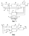
- the electronic control circuit or "ballast" for fluorescent lighting lamps or tubes which is the object of the present invention, essentially consists of an electronic filtering stage PFC, at the input of which the voltage VR is applied, which has the task of keeping the power factor high, a service power supply AS, which has the task of generating the service power, a striking or control circuit CP of the fluorescent lighting lamps or tubes LF and a microcontroller M, provided with edge logic, suitable to ensure radio communication, through the antenna A, power measurement, diagnostics of the control circuit CP of the fluorescent lighting lamps or tubes LF too.
- the logic of the microcontroller M consists of a software applicative program allowing to check the status of the voltage VN coming out from the filtering stage PFC and evaluate whether lighting on or not the lamps or tubes LF, measure the power and energy absorbed by the circuit, keep updated and store the perpetual time and energy counters, assess the environmental brilliancy, through the light sensor SL, and adjust accordingly the power supplied by the lamps or tubes LF, measure the temperature inside the microcontroller M, provide radio communication for monitoring the operation status and perform diagnostics on the proper functioning of the striking and control circuit CP and fluorescent lamps or tubes LF.
- the electronic control circuit is divided into three printed circuit boards, referred to respectively as BARCUN module (which contains the power part of the "ballast"), MODBAN module (a single side BARCUN module, containing three MOS and a diode of power to be dissipated) and RADRUS module (containing the microcontroller M and the circuits related to the radio communication).
- BARCUN module which contains the power part of the "ballast”
- MODBAN module a single side BARCUN module, containing three MOS and a diode of power to be dissipated
- RADRUS module containing the microcontroller M and the circuits related to the radio communication.
- the electronic filtering stage PFC has the task of generating a voltage VA equal to 390 Volt at direct current, starting from the input supply voltage VR, which can be both direct and alternate.
- the electronic filtering stage PFC consists of a common way input filter and a diodes bridge, connected to a classic configuration circuit, based on the ST L6562 integrated circuit, STB9NK60Z power MOS, RS3J power diode, 0.9 mH EF25H11 transformer and 22 uF and 450 Volt electrolytic capacitor; adjustment of the voltage VA is obtained through a chain of resistors and, in case of need, it is possible to increase the adjusted voltage from 390 Volt to 420 Volt, through a resistor controlled by the RADRUS module.
- the current IP coming out from the filtering stage PFC is measured by a series of resistors set in parallel, while the voltage VN coming out from the filtering stage PFC is measured through another chain of resistors set in series; the feedback compensation is obtained through the components of the BARCUN module by inserting a pole into the origin and a zero to improve the circuit response to impulsive load changes.
- the service power supply AS has the task of generating the voltage V necessary for the operation of the RADRUS module and integrated circuits L6562 and L6574 and is made of a BUCK type circuit, based on the PowerInt LNK306G integrated circuit, a 1.12 mH inductor and a recirculation diode of the BARCUN module.
- the control circuit is connected at the voltage VA and starts as soon as there is voltage VR; the adjustment is accomplished by a resistive divider, a capacitor and a diode, all inserted into the BARCUN module, while another capacitor of the BARCUN module has the task of running the soft-start function.
- the striking and control circuit CP of the fluorescent lighting lamps or tubes LF is based on the integrated circuit ST L6574 of the BARCUN module and the lamps or tubes LF are controlled by a classic half-bridge circuit consisting of two STB9NK60ZB MOS of the MODBAN module and a resonant LC circuit of the BARCUN module.
- the component values change depending on the number and type of the fluorescent lighting lamps or tubes LF to be switched on; when the lighting lamps or tubes LF to be switched on are two, they are placed in parallel and a transformer is used to keep balanced the current which passes through them, indispensable function when the dimmer circuit intervenes in order to reduce brilliancy so as one of the lamps or tubes LF does not switch off.
- a capacitor is also provided in series with the resonant circuit, which is responsible for blocking any direct component of the current; a series of resistors are then inserted in parallel to such a capacitor, which are responsible for removing light rings which, sometimes, form in the fluorescent lighting lamps or tubes LF.
- L6574 integrated circuit is provided with the following components, suitable to perform the functions required for the proper switching on of the fluorescent lamps or tubes LF:
- Control and radio communication of the whole ballast are entrusted to the 8-bits microcontroller M, in particular consisting of the MC13213 "Freescale-Motorola” chip, composed of a processor (CPU) of the HCS08 family and an 802.15.4 modem, operating at 2.4 GHz (the programming language used for implementation is ANSI-C, within the development system "Metrowerks Code Warrior” licensed by "Freescale-Motorola”).
- the main features of the processor (CPU) of the microcontroller M are the following:
- the main functions performed by the microcontroller M through the running of the software applicative program are the following:
- the microcontroller M is programmed so that measure of the network voltage VR and network current IR occurs sampling every millisecond the two reconditioned signals VR, IR, derived from the power supply stage and placed into two 10-bits channels ADC of the processor of the microcontroller M.
- the measure of the environmental brilliancy occurs by sampling every five milliseconds the sensor signal SL, such as a phototransistor, conditioned by means of an amplification network connected with a 10-bits ADC of the microcontroller M.
- This conditioning circuit provides two levels of amplification, to control the microcontroller M, and before every sampling, the microcontroller M changes the amplification level and accumulates the results separately, thus parallelizing the obtained moving averages with the two gains.
- microcontroller M for adjusting, during automatic operation, the lighting flow of each lamp or tube LF, and are also recovered via radio and analyzed by the local or central counter C in order to establish a brilliancy set-point, which must chased by the lamp or tube LF.
- the circuit temperature measure occurs by sampling every ten milliseconds the signal of a sensor NTC mounted on the printed circuit board and connected with a 10-bits channel ADC of the microcontroller M.
- a moving average is extracted from the measure, which is used by the microcontroller M to inferiorly limit the excursions of the dimmer of the striking and control circuit CP of the fluorescent lamps or tubes LF when, in presence of certain types of lamps or tubes LF, the temperature remains below a certain threshold.
- the microcontroller M interfaces the striking and control circuit CP of the fluorescent lamps or tubes LF through four signals:
- Supply voltage measure of the microcontroller M occurs by sampling every millisecond the voltage VN at the regulator input which powers the microcontroller M itself, connected with its 10-bits ADC channel.
- the radio transmitter RT is compatible with the 802.15.4 standard wireless protocol, used, for reasons of computational opportunity, both for reception and transmission according to the "packet" mode, which allows the trans-reception of messages.
- the microcontroller M typically gains access to the status and/or control registers of the transmitter RT, transmission buffers and reception buffers and controls their operation.
- Execution of the pending activities is signaled by the transmitter RT through the pin IRQ of the microcontroller M.
- Implementation of the "interrupt" processes of the ballast occurs, in particular, as a result of commands given by the microcontroller M in accordance with the parameters coming from the counter or timer C (high priority intervention), depending on the measured values, at each sampling made every millisecond, of the network voltage VR, network current IR, voltage VN entering the microcontroller M, voltage VC present at the cathodes of the fluorescent lamps or tubes LF, produced brilliancy level LX, reached temperature T an presence or not of the cathodes CTD of the fluorescent lamps or tubes LF.
- the algorithm for calculating the energy is distributed in two processes, referred to as "interrupt process” and "passing sequential applicative process”.
- the period counter PINT and time counter TINT are incremented at each interrupt and, when TINT reaches 200 value (therefore, every two hundreds milliseconds), a prefixed indication is provided for the passing sequential (applicative) process PSP (with the time counter of the passing sequential process TPSP set equal to 1), that will perform the rest of the process.
- the adjusting process of the brilliancy is performed in a passing sequential (applicative) process which uses a series of variables consisting of the results of samplings made on the basis of the interrupt process.
- every five milliseconds is sampled the voltage VSL of the sensor or phototransistor SL and updated the gain G of the operational amplifier which affects the signal thereof towards the microcontroller M.
- the variables LXHM and LXLM are, furthermore, available via radio for the central counter C, which uses them to calculate and set on the lamp or tube LF the appropriate high SPH or low SPL set-point.
- an emergency condition it is possible to perform the switching on of the emergency ballast, according to which the microcontroller M, before switching on the fluorescent lamps or tubes LF, performs the recognition and check of the network frequency, by controlling the normal switching on (full power) in case it detects a frequency of a primary network equal to 50 Hz and the emergency switching (low power) in case it detects a frequency (of emergency) of a secondary network equal to 56 Hz at direct current.
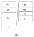
- the analysis of the supply frequency and subsequent decision to switch on, by the microcontroller M memory involves the central counter C (which performs squaring of the network voltage sampled every millisecond and determines the number of fronts and stay time), PWM power controller (which performs the analysis of the number of fronts and check of the stay time determines the network frequency) and brilliancy regulator LX (which provides waiting for the recognition of the network frequency by the PWM controller and performs the decision to switch on at full power or not when the network frequency has been recognized).
- the turning on of the fluorescent lamps or tubes LF is affected by the further parameter of the emergency power; in such a case, the lamps or tubes LF can be kept off if the parameter related to the emergency power has the value equal to 0 or on at the power indicated by the aforesaid parameter if the same is different from 0.
Landscapes
- Engineering & Computer Science (AREA)
- Computer Networks & Wireless Communication (AREA)
- Circuit Arrangements For Discharge Lamps (AREA)
Applications Claiming Priority (1)
| Application Number | Priority Date | Filing Date | Title |
|---|---|---|---|
| ITVI2009A000149A IT1394654B1 (it) | 2009-06-22 | 2009-06-22 | Circuito elettronico di controllo per lampade o tubi fluorescenti |
Publications (1)
| Publication Number | Publication Date |
|---|---|
| EP2296446A1 true EP2296446A1 (de) | 2011-03-16 |
Family
ID=41682543
Family Applications (1)
| Application Number | Title | Priority Date | Filing Date |
|---|---|---|---|
| EP20100425211 Ceased EP2296446A1 (de) | 2009-06-22 | 2010-06-21 | Vorschaltgerät für Leuchtstofflampen |
Country Status (2)
| Country | Link |
|---|---|
| EP (1) | EP2296446A1 (de) |
| IT (1) | IT1394654B1 (de) |
Cited By (2)
| Publication number | Priority date | Publication date | Assignee | Title |
|---|---|---|---|---|
| CN109564704A (zh) * | 2016-09-16 | 2019-04-02 | 英特尔公司 | 虚拟现实/增强现实设备和方法 |
| CN120302494A (zh) * | 2025-05-30 | 2025-07-11 | 深圳市优威电气技术有限公司 | 一种自动匹配灯管电压的电子整流器 |
Citations (5)
| Publication number | Priority date | Publication date | Assignee | Title |
|---|---|---|---|---|
| US20020109466A1 (en) * | 2001-02-09 | 2002-08-15 | Patent-Treuhand-Gesellschaft Fuer Elektrische Gluihlampen Mbh | Ballast for operating electric lamps |
| US20050093477A1 (en) * | 2003-10-17 | 2005-05-05 | Ruhe Shi | Electronic ballast having end of lamp life, overheating, and shut down protections, and reignition and multiple striking capabilities |
| US20050179404A1 (en) * | 2004-02-13 | 2005-08-18 | Dragan Veskovic | Multiple-input electronic ballast with processor |
| EP1724903A2 (de) * | 2005-05-17 | 2006-11-22 | Beghelli S.p.A. | Integriertes System für Beleutung und Notbeleuchtung |
| WO2007036886A2 (en) * | 2005-09-30 | 2007-04-05 | Koninklijke Philips Electronics, N.V. | Wireless building automation and control network, digital ballast and wireless control device |
-
2009
- 2009-06-22 IT ITVI2009A000149A patent/IT1394654B1/it active
-
2010
- 2010-06-21 EP EP20100425211 patent/EP2296446A1/de not_active Ceased
Patent Citations (5)
| Publication number | Priority date | Publication date | Assignee | Title |
|---|---|---|---|---|
| US20020109466A1 (en) * | 2001-02-09 | 2002-08-15 | Patent-Treuhand-Gesellschaft Fuer Elektrische Gluihlampen Mbh | Ballast for operating electric lamps |
| US20050093477A1 (en) * | 2003-10-17 | 2005-05-05 | Ruhe Shi | Electronic ballast having end of lamp life, overheating, and shut down protections, and reignition and multiple striking capabilities |
| US20050179404A1 (en) * | 2004-02-13 | 2005-08-18 | Dragan Veskovic | Multiple-input electronic ballast with processor |
| EP1724903A2 (de) * | 2005-05-17 | 2006-11-22 | Beghelli S.p.A. | Integriertes System für Beleutung und Notbeleuchtung |
| WO2007036886A2 (en) * | 2005-09-30 | 2007-04-05 | Koninklijke Philips Electronics, N.V. | Wireless building automation and control network, digital ballast and wireless control device |
Non-Patent Citations (3)
| Title |
|---|
| "L6574 CFL/TL Ballast Driver Preheat and Dimming", APPLICATION NOTE ST MICROELECTRONICS, XX, XX, 15 May 2001 (2001-05-15), pages 1 - 9, XP002431248 * |
| FREESCALE SEMICONDUCTOR: "MC13211/212/213 - ZigBee - Compliant Platform - 2.4 GHz low power Transceiver for the IEEE 802.15.4 Standard plus microcontroller", FREESCALE SEMICONDUCTOR - TECHNICAL DATA, no. MC1321x Rev. 1.2 05/2007, February 2007 (2007-02-01), pages 1 - 70, XP002570116, Retrieved from the Internet <URL:http://pdf1.alldatasheet.com/datasheet-pdf/view/183235/FREESCALE/MC13213.html> [retrieved on 20100223] * |
| SANDRINI F ET AL: "AN993 Application Note, Electronic Ballast with PFC using L6574 and L6561", APPLICATION NOTE ST MICROELECTRONICS, XX, XX, no. AN993, 15 July 1999 (1999-07-15), pages 1 - 15, XP002431247 * |
Cited By (3)
| Publication number | Priority date | Publication date | Assignee | Title |
|---|---|---|---|---|
| CN109564704A (zh) * | 2016-09-16 | 2019-04-02 | 英特尔公司 | 虚拟现实/增强现实设备和方法 |
| CN109564704B (zh) * | 2016-09-16 | 2023-11-21 | 英特尔公司 | 虚拟现实/增强现实设备和方法 |
| CN120302494A (zh) * | 2025-05-30 | 2025-07-11 | 深圳市优威电气技术有限公司 | 一种自动匹配灯管电压的电子整流器 |
Also Published As
| Publication number | Publication date |
|---|---|
| ITVI20090149A1 (it) | 2010-12-23 |
| IT1394654B1 (it) | 2012-07-05 |
Similar Documents
| Publication | Publication Date | Title |
|---|---|---|
| US11963272B2 (en) | Data acquisition methods and apparatus for a network connected LED driver | |
| CN109891937B (zh) | 照明控制自动化系统 | |
| US7675758B2 (en) | Power converter with an adaptive controller and method of operating the same | |
| CN111165075B (zh) | 智能开关设备及其中央控制系统和电源 | |
| US9197132B2 (en) | Power converter with an adaptive controller and method of operating the same | |
| US20150257229A1 (en) | Lighting device monitor and communication apparatus | |
| US10959307B2 (en) | Load control device configured to operate in two-wire and three-wire modes | |
| US8446101B2 (en) | Control switch | |
| CN111351979B (zh) | 过流检测电路、过流保护装置、线路板及空调器 | |
| TW200818988A (en) | System and method for current and/or temperature control of light fixtures | |
| CN111505370B (zh) | 过零检测电路、芯片、智能开关及过零检测方法 | |
| US12074446B2 (en) | Methods and arrangements for load control | |
| US10231297B2 (en) | Lighting apparatus control switch and method | |
| JP2012175751A (ja) | 配電システム | |
| EP2296446A1 (de) | Vorschaltgerät für Leuchtstofflampen | |
| US10910885B2 (en) | Power transmission-side apparatus | |
| CN105783187B (zh) | 一种空调节能控制系统 | |
| EP3393209B1 (de) | System zur regelung des minimalen ausgangsstroms einer led-dimmstromversorgung | |
| US11166357B2 (en) | Techniques for implementing a certain light characteristic | |
| CN114466481B (zh) | 一种检测led恒压驱动电源空载的电路及方法、led驱动器 | |
| CN214708104U (zh) | 一种调光器及其灯具 | |
| CN110504899B (zh) | 电机控制电路及空调器 | |
| JP6012130B2 (ja) | クラスタ状態監視装置 | |
| KR101433006B1 (ko) | 정보 통신 기기 모듈단위 실시간 에너지 제어장치 | |
| CN100396164C (zh) | 数字式高强度气体放电灯适配器 |
Legal Events
| Date | Code | Title | Description |
|---|---|---|---|
| PUAI | Public reference made under article 153(3) epc to a published international application that has entered the european phase |
Free format text: ORIGINAL CODE: 0009012 |
|
| AK | Designated contracting states |
Kind code of ref document: A1 Designated state(s): AL AT BE BG CH CY CZ DE DK EE ES FI FR GB GR HR HU IE IS IT LI LT LU LV MC MK MT NL NO PL PT RO SE SI SK SM TR |
|
| AX | Request for extension of the european patent |
Extension state: BA ME RS |
|
| 17P | Request for examination filed |
Effective date: 20110825 |
|
| 17Q | First examination report despatched |
Effective date: 20120308 |
|
| STAA | Information on the status of an ep patent application or granted ep patent |
Free format text: STATUS: THE APPLICATION HAS BEEN REFUSED |
|
| 18R | Application refused |
Effective date: 20151001 |