EP2296452A2 - Wärmebrückenerweiterungen für eine Modulkarosserie-Schnittstelle - Google Patents
Wärmebrückenerweiterungen für eine Modulkarosserie-Schnittstelle Download PDFInfo
- Publication number
- EP2296452A2 EP2296452A2 EP10173478A EP10173478A EP2296452A2 EP 2296452 A2 EP2296452 A2 EP 2296452A2 EP 10173478 A EP10173478 A EP 10173478A EP 10173478 A EP10173478 A EP 10173478A EP 2296452 A2 EP2296452 A2 EP 2296452A2
- Authority
- EP
- European Patent Office
- Prior art keywords
- module
- extension
- wall
- chassis
- pba
- Prior art date
- Legal status (The legal status is an assumption and is not a legal conclusion. Google has not performed a legal analysis and makes no representation as to the accuracy of the status listed.)
- Withdrawn
Links
- 239000003351 stiffener Substances 0.000 claims description 22
- 239000000463 material Substances 0.000 claims description 6
- 230000003068 static effect Effects 0.000 claims description 2
- 230000000717 retained effect Effects 0.000 description 6
- 239000004020 conductor Substances 0.000 description 4
- 230000037431 insertion Effects 0.000 description 4
- 238000003780 insertion Methods 0.000 description 4
- 230000013011 mating Effects 0.000 description 3
- 229910052782 aluminium Inorganic materials 0.000 description 2
- XAGFODPZIPBFFR-UHFFFAOYSA-N aluminium Chemical compound [Al] XAGFODPZIPBFFR-UHFFFAOYSA-N 0.000 description 2
- 230000000712 assembly Effects 0.000 description 2
- 238000000429 assembly Methods 0.000 description 2
- 238000004519 manufacturing process Methods 0.000 description 2
- RYGMFSIKBFXOCR-UHFFFAOYSA-N Copper Chemical compound [Cu] RYGMFSIKBFXOCR-UHFFFAOYSA-N 0.000 description 1
- 101000724590 Loxosceles arizonica Dermonecrotic toxin LarSicTox-alphaIB2a Proteins 0.000 description 1
- 101000761451 Loxosceles boneti Dermonecrotic toxin LbSicTox-alphaIB1a Proteins 0.000 description 1
- 101000915115 Loxosceles gaucho Dermonecrotic toxin LgSicTox-alphaIA1 Proteins 0.000 description 1
- 101000915128 Loxosceles intermedia Dermonecrotic toxin LiSicTox-alphaIA1a Proteins 0.000 description 1
- 101000915125 Loxosceles intermedia Dermonecrotic toxin LiSicTox-alphaIA1bi Proteins 0.000 description 1
- 101000915126 Loxosceles intermedia Dermonecrotic toxin LiSicTox-alphaIA1bii Proteins 0.000 description 1
- 101000964274 Loxosceles laeta Dermonecrotic toxin LlSicTox-alphaIII1i Proteins 0.000 description 1
- 101000964272 Loxosceles laeta Dermonecrotic toxin LlSicTox-alphaIII1ii Proteins 0.000 description 1
- 101000724586 Loxosceles reclusa Dermonecrotic toxin LrSicTox-alphaIB1 Proteins 0.000 description 1
- 101000915113 Loxosceles similis Dermonecrotic toxin LsSicTox-alphaIA1 Proteins 0.000 description 1
- SOWHJXWFLFBSIK-UHFFFAOYSA-N aluminum beryllium Chemical compound [Be].[Al] SOWHJXWFLFBSIK-UHFFFAOYSA-N 0.000 description 1
- 239000002131 composite material Substances 0.000 description 1
- 229910052802 copper Inorganic materials 0.000 description 1
- 239000010949 copper Substances 0.000 description 1
- 229910003460 diamond Inorganic materials 0.000 description 1
- 239000010432 diamond Substances 0.000 description 1
- 230000009977 dual effect Effects 0.000 description 1
- 230000000694 effects Effects 0.000 description 1
- 238000000605 extraction Methods 0.000 description 1
- 239000011159 matrix material Substances 0.000 description 1
- 229910052751 metal Inorganic materials 0.000 description 1
- 239000002184 metal Substances 0.000 description 1
- 230000002093 peripheral effect Effects 0.000 description 1
- 230000003746 surface roughness Effects 0.000 description 1
Images


Classifications
-
- H—ELECTRICITY
- H05—ELECTRIC TECHNIQUES NOT OTHERWISE PROVIDED FOR
- H05K—PRINTED CIRCUITS; CASINGS OR CONSTRUCTIONAL DETAILS OF ELECTRIC APPARATUS; MANUFACTURE OF ASSEMBLAGES OF ELECTRICAL COMPONENTS
- H05K7/00—Constructional details common to different types of electric apparatus
- H05K7/14—Mounting supporting structure in casing or on frame or rack
- H05K7/1401—Mounting supporting structure in casing or on frame or rack comprising clamping or extracting means
- H05K7/1402—Mounting supporting structure in casing or on frame or rack comprising clamping or extracting means for securing or extracting printed circuit boards
- H05K7/1404—Mounting supporting structure in casing or on frame or rack comprising clamping or extracting means for securing or extracting printed circuit boards by edge clamping, e.g. wedges
-
- H—ELECTRICITY
- H05—ELECTRIC TECHNIQUES NOT OTHERWISE PROVIDED FOR
- H05K—PRINTED CIRCUITS; CASINGS OR CONSTRUCTIONAL DETAILS OF ELECTRIC APPARATUS; MANUFACTURE OF ASSEMBLAGES OF ELECTRICAL COMPONENTS
- H05K7/00—Constructional details common to different types of electric apparatus
- H05K7/20—Modifications to facilitate cooling, ventilating, or heating
- H05K7/2039—Modifications to facilitate cooling, ventilating, or heating characterised by the heat transfer by conduction from the heat generating element to a dissipating body
- H05K7/20436—Inner thermal coupling elements in heat dissipating housings, e.g. protrusions or depressions integrally formed in the housing
-
- H—ELECTRICITY
- H05—ELECTRIC TECHNIQUES NOT OTHERWISE PROVIDED FOR
- H05K—PRINTED CIRCUITS; CASINGS OR CONSTRUCTIONAL DETAILS OF ELECTRIC APPARATUS; MANUFACTURE OF ASSEMBLAGES OF ELECTRICAL COMPONENTS
- H05K7/00—Constructional details common to different types of electric apparatus
- H05K7/20—Modifications to facilitate cooling, ventilating, or heating
- H05K7/20536—Modifications to facilitate cooling, ventilating, or heating for racks or cabinets of standardised dimensions, e.g. electronic racks for aircraft or telecommunication equipment
Definitions
- the present invention relates generally to an apparatus for mounting and fastening a printed board assembly (PBA) module to one or more channels of a rack or chassis. More particularly, the present invention relates to a thermal bridge PBA module with thermal bridge extensions that can be expanded transversely for mounting, fastening and heat sinking a PBA module to one or more channels of a rack or chassis.
- PBA printed board assembly
- Elongated wedge clamp assemblies are currently used for fastening a printed board assembly (PBA) or a PBA module to a channel of a rack or chassis.
- the wedge clamp assembly typically includes a plurality of wedges, each wedge having one or two ends with sloped surfaces. The sloped surfaces of each wedge abut against the sloped surface of the adjacent wedge.
- a screw extends length-wise through each wedge and connects together the plurality of wedges.
- the end wedge remote from the head of the screw typically has a threaded bore engaged by the screw such that a clockwise rotation of the screw draws the wedges toward each other, causing the wedges to deflect transversely from each other on the sloped abutting surfaces.
- This axial to transverse motion increases the assembly's width as its length is compressed, and thereby presses one side of the PBA or PBA module against the chassis channel wall, fastening the PBA or PBA module tightly within the chassis channel. Subsequently rotating the screw in a counterclockwise direction moves the wedges apart from each other, to bring them back into longitudinal alignment with each other and, thereby, to release the clamping force on the PBA or PBA module.
- the expansion pressure of the wedge clamp is intended to mechanically lock the PBA or PBA module in position via static friction and to provide a low thermal resistance between the PBA or PBA module size and chassis channel wall that are in direct contact, as later described and shown in Figure 1 .
- the thermal resistance across a thermal interface is a function of the interfacing materials, the surface roughness, the contact area, and the contact pressure.
- the thermal resistance from the other PBA or PBA module side through the expanded wedge clamp and to the other chassis channel wall is much higher. This is due to the relatively small contact areas at the abutted hollow sloped wedge interfaces. These small contact areas create points of high thermal resistance, often referred to as thermal bottlenecks.
- thermal bridge PBA modules are used, wherein thermal bridge structures are located on either side of the PBA such that the PBA is sandwiched between them, later described and shown in Figure 2 .
- Each thermal bridge structure has an external skin that is displaced from the printed board (PB) surface as needed to provide component clearance.
- Rib or post extensions from the thermal bridge external skin to the PB surface typically at the PB periphery and periodically in between, provide PB mechanical support and PB heat sinking. Extensions from the thermal bridge external skin to the top of components provide component heat sinking.
- the thermal bridge external skin is not displaced from the PB surface and is in direct contact with the PB surface on either side to keep this interface narrow.
- a wedge clamp is mounted on one side of this interface to provide pressure to mechanically lock the thermal bridge PBA module in position.
- one thermal bridge is in direct contact with a chassis channel wall on one side and with one PB side on the other.
- the other thermal bridge is in direct contact with the other PB side on one side and with one wedge clamp side on the other side.
- the other wedge clamp side is in direct contact with the other chassis channel wall.
- the thermal bridge on one side typically has a much lower thermal resistance to the chassis than the thermal bridge on the opposite side. Components on one side of the PBA module will therefore have a much higher thermal resistance to the chassis than components on the other side.
- a PBA module for use with an expansion clamp in each of one or more chassis channels.
- the structure of the PBA module allows for flexion of some of the PBA module parts, allowing for better mechanical fit and thermal conduction between the PBA module and the one or more chassis channels.
- a PBA module for use with a single expansion clamp in a single chassis channel at each chassis interface.
- the PBA module comprises a printed board assembly sandwiched between a first thermal bridge stiffener with a first side portion and a first extension, and a second thermal bridge stiffener with a second side portion and a second extension.
- the first extension comprises a first external wall and a first internal wall
- the second extension comprises a second external wall and a second internal wall.
- the first extension is integral or attached to the first side portion of the first thermal bridge stiffener.
- the second extension is integral or attached to the second side portion of the second thermal bridge stiffener.
- the expansion clamp is fastened to the internal wall of the first or second thermal bridge stiffener extension.
- the first internal wall and the second internal wall each have at rest a first position, and in response to pressure applied to the first internal wall and the second internal wall, the first and second internal walls move laterally to a second position.
- the distance between the first internal wall and the second internal wall is greater at the second position than at the first position.
- a PBA module for use with an expansion clamp in each of two chassis channels shared with those of adjacent PBA modules at each module-chassis interface.
- the PBA module comprises a printed board assembly (PBA) sandwiched between a thermal bridge stiffener pair.
- the thermal bridge stiffener pair comprises a first structure with a first extension, and a second structure with a second extension.
- the first extension comprises a first external wall and a first internal wall.
- the second extension comprises a second external wall and a second internal wall.
- the expansion clamp is affixed to the external wall of the first or second extension.
- the first extension is integral or attached to the first structure, and the second extension is integral or attached to the second structure.
- a space is defined between the external walls of adjacent PBA modules sharing a common chassis channel.
- the external walls of the adjacent PBA modules each have a first position, and in response to pressure applied to the external walls, each external wall moves laterally to a second position. At the second position the defined space between the external walls is greater
- FIG. 1 depicts a bottom cross section view of a prior art configuration for a printed board assembly (PBA) 100 retained within a chassis channel with a locking wedge clamp assembly.
- the PBA 100 is retained in an elongated chassis channel 112 formed in a chassis 110 by means of locking wedge clamp assembly 120.
- Locking wedge claim assembly 120 comprises wedge clamp interfaces 122. When relaxed (in the elongation aligned position), locking wedge clamp assembly 120 provides enough clearance for PBA insertion and removal.
- MIB master interconnect board
- thermal conduction takes place from electrical components 130 to the interface 114 through the printed board (PB) surface and buried conductor layers 150.
- the path of thermal conduction is shown with arrows 160.
- Thermal conduction from the body of one of the electrical components 130 such as the upper ball grid array (BGA) device shown in Figure 1
- BGA ball grid array
- other electrical components 130 such as the lower quad flat pack device shown in Figure 1
- TIM interfacial thermal interface material
- Thermal condition then takes place through the PB surface and buried conductor layers 150, and next through the wedge clamp interfaces 122 on one side and the direct chassis interface 114 on the other side.
- Most of the thermal conduction to the chassis takes place at interface 114 due to the direct contact between the PB and the chassis. Thermal conduction from the PB through locking wedge clamp assembly 120 to the chassis is much less because of the poor thermal conduction through the wedge clamp assembly.
- any horizontal misalignment due to fabrication and assembly tolerance buildup, translates into module-MIB connector alignment and mating issues or built in stress and strain along the horizontal axis at the mated module-MIB connector interface after the PBA is locked in position.
- the chassis channel must be wide enough to provide clearance for the widest PBA chassis interface to facilitate ease of PBA insertion and extraction from the chassis.
- nominal dimensioning positions the PBA chassis interface in the center of the chassis for a mated condition. This allows room for the PBA to shift in any direction, or float, as the connectors are mated.
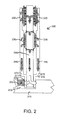
- FIG. 2 depicts a bottom cross section view of another prior art configuration for a thermal bridge printed board assembly (PBA) module 200 retained within a chassis channel with a locking wedge clamp assembly.
- Thermal bridge PBA module 200 is retained in an elongated channel 212 formed in a chassis 210 by means of a locking wedge clamp assembly 220.
- Locking wedge clamp assembly 220 comprises wedge clamp interfaces 222.
- Thermal conduction from the components 230 follows the paths shown with the plurality of arrows 260, through a printed board (PB) 250 and the thermal bridge stiffeners 270 on both sides.
- the right thermal bridge stiffener 272 has direct contact between its left side and the right PB side and between its right side and the right chassis channel wall of chassis 210.
- the left thermal bridge stiffener 271 has direct contact between its right side and the left PB side and between its left side and the right wedge clamp interface 222.
- the left wedge clamp interface 222 is in direct contact with the left chassis channel wall of the chassis 210.
- Components on the left side of this thermal bridge PBA module will have a higher thermal resistance to the chassis than components on the right side.
- any horizontal misalignment due to fabrication and assembly tolerance buildup, translates into module-MIB connector alignment and mating issues or built in stress and strain along the horizontal axis at the mated module-MIB connector interface after the thermal bridge PBA module is locked in position.
- Figures 3a-3c illustrate an exemplary locking wedge clamp assembly 300 of the present invention.
- Figures 3a and 3b show screw end and side views, respectively, of locking wedge clamp assembly 300 in the relaxed position (elongation aligned).
- Locking wedge clamp assembly 300 comprises a plurality of wedges, including a first wedge 320, a second wedge 321, a third wedge 322, a fourth wedge 323, a fifth wedge 324, a sixth wedge 325, and a seventh wedge 326.
- Locking wedge clamp assembly 300 also comprises an axial tension screw 310. Screw 310 extends length-wise through each of the plurality of wedges, connecting the plurality of wedges together. In the relaxed position, the wedges are aligned with each other, such that a first side 327 is flush with the first sides 327 of the other wedges, and a second side 328 of each wedge is flush with the second sides 328 of the other wedges.
- Figure 3c shows a side view of the locking wedge clamp assembly of Figures 3a and 3b in the expanded position (elongation compressed).
- axial tension screw 310 is rotated, causing of the plurality of wedges 320 to move transversely relative to each other.
- first sides 327 of the second wedge 321, fourth wedge 323, and sixth wedge 325 are now located on a plane above the first sides 327 of first wedge 320, third wedge 322, fifth wedge 324, and seventh wedge 326, as shown in Figure 3c .
- a plurality of arrows 330 in Figure 3c show where thermal bottlenecks may occur when locking wedge assembly 300 is in the expanded position. Thermal bottlenecks occur because of the structure and movement of the wedges.
- Each wedge is hollow to provide clearance for the axial tension screw in both relaxed and expanded positions.
- the bottom sides 328 of the first wedge 320, third wedge 322, fifth wedge 324 and seventh wedge 326 are against the PBA while the top sides 327 of the second wedge 321, fourth wedge 323 and sixth wedge 325 are against the chassis.
- the only thermal path through the expanded wedge clamp is through the small sloped abutted interfaces between adjacent wedges.
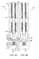
- FIG. 4a depicts a bottom cross section view of a thermal bridge printed board assembly (PBA) module 400 according to one embodiment of the present invention.
- Thermal bridge PBA module 400 comprises a first side portion 422, a second side portion 424, a first extension 426, and a second extension 428.
- First side portion 422 and second side portion 424 may also be referred to as a thermal bridge-stiffener pair with chassis interface extensions.
- First side portion 422 and second side portion 424 may be referred to as a first thermal bridge structure and a second thermal bridge structure.
- PBA 410 is attached within PBA module 400.
- PBA 410 may be sandwiched between first side portion 422 and second side portion 424 within PBA module 400.
- First extension 426 may be manufactured to be integral with first side portion 422 and second extension 428 may be manufactured to be integral with second side portion 424.
- first extension 426 and second extension 428 may be separate parts, and may be affixed to first side portion 422 and second side portion 424.
- Interfacial thermal interface material is used between the top of each PBA component and side portion to reduce the component package to side portion thermal resistance.
- Ball grid array (BGA) and peripheral leaded component packages are shown in this example, but other device types may also be used.
- First side portion and second side portion may be custom milled to provide an extension from the side portion to each component to minimize the interfacial TIM thickness and thermal resistance at each component.
- Each side portion may be constructed from pure aluminum. In alternate embodiments, each side portion may be constructed from an aluminum beryllium composite, or a diamond filled aluminum matrix. Extensions 426, 428 are preferably made from a flexible thermally conductive material.
- extensions 426, 428 may be made as an integral part of the side portions and may thus comprise the same material as first side portion 422 and second side portion 424.
- one or both of extensions 426, 428 may be made separately and from a different material, such as copper, for example.
- extensions 426,428 may be bolted, bonded, or welded to first side portion 422 and second side portion 424.
- first extension 426 and second extension 428 extend into a channel 510 in chassis 500.
- Channel 510 comprises a left channel wall 512 and a right channel wall 514.
- both first and second extensions 426 and 428 share a common expansion clamp assembly 300 bolted to one of the extensions 426 or 428 and a common chassis channel 510 at each module-chassis interface.
- the chassis comprises a metal frame on which electronics modules, such as a Standard Electronics Module format E (SEM-E), are mounted.
- Electronic component package types that may be mounted on the PBA and thermally bonded to the thermal bridge stiffeners of such modules include multichip module (MCM), ball grid array (BGA), dual/quad flat packs, SMD-1, as well as other electronic devices or components.
- MCM multichip module
- BGA ball grid array
- SMD-1 dual/quad flat packs
- First extension 426 comprises an external wall 432 and an internal wall 434.
- Second extension 428 also comprises an external wall 432 and an internal wall 434.
- Internal walls 434 of first extension 426 and second extension 428 may form a modified v-shape, as shown in Figure 4a .
- first extension 426 is at an angle and at least a portion of second extension 428 is at an angle.
- the angle and length of the angled sections of the extensions are determined as needed so that the extensions extend into a common chassis channel, as shown in Figures 4a and 4b .
- the first side portion 422 may comprise a first edge 442 and the second side portion 424 may comprise a second edge 444.
- a space 446 may be present between first edge 442 and internal wall 434 of first extension 426, and between second edge 444 and internal wall 434 of second extension 428. Space 446 provides for flexure of first extension 426 and second extension 428.
- the amount of flexure needed for first extension 426 and second extension 428 may be the difference between the unclamped clearance-fit configuration of Figure 4a and the clamped press-fit configuration of Figure 4b . This amounts to clearance 452 between the first external wall 432 of the first extension 426 and the left chassis channel wall 512 and clearance 454 between the second external wall 432 of second extension 428 and the right chassis channel wall 514, as depicted in Figure 4a .
- the expansion clamp assembly 300 is positioned between the portions of first extension 426 and second extension 428 that extend into chassis channel 510, as shown in Figure 4a .
- the printed board assembly (PBA) is sandwiched between first side portion 422 and second side portion 424.
- the screw on the wedge clamp assembly is turned and the wedge pieces of the assembly translate to the expanded position shown in Figure 3c .
- Figure 4b shows the module of Figure 4a when the wedge clamp assembly is in the expanded position. The module position remains the same whether in the unclamped clearance-fit or clamped press-fit configurations.
- first extension 426 if flexed, moving laterally toward the left channel wall 512, filling the left clearance-fit 452 at the module-chassis interface from Figure 4a .
- External wall 432 of first extension 426 now abuts left channel wall 512.
- the second extension 428 extension is also flexed, having moved toward the right channel wall 514 and filling the right clearance-fit 454 at the module-chassis interface from Figure 4a .
- Exterior surface 432 of second extension 428 now abuts right channel wall 514.
- each extension The degree of movement or flexion of each extension is small enough that permanent deformation does not occur, and each extension will return to the configuration shown in Figure 4a when the wedge clamp assembly is returned to the relaxed position of Figures 3a and 3b .
- the ability of the extensions to flex in this manner ensures good conformance between external wall 432 of first extension 426 and left chassis channel wall 512 and between external wall 432 of second extension 428 and right chassis channel wall, and minimal thermal resistance at the module-chassis interface.
- the module 400 is not displaced vertically or horizontally as it is locked into position, so that no built-in stress or strain are applied to the mated module-MIB connector interface.
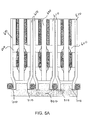
- FIG. 5a depicts a bottom cross section view of a thermal bridge PBA module according to another embodiment of the present invention.
- Chassis 700 may comprise a plurality of channels 710.
- Thermal bridge PBA modules 600 may each comprise a thermal bridge stiffener 610 with extension on either side of the PBA.
- the extensions of thermal bridge stiffener extensions 610 are in unclamped position.
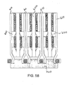
- Figure 5b depicts a bottom cross section view of the thermal bridge PBA module 600 of Figure 5a with the extensions of its thermal bridge stiffeners 610 in the clamped position.
- the thermal bridge extensions of each thermal bridge PBA module share a chassis channel and a wedge clamp assembly on each side with the adjacent thermal bridge PBA module.
- two wedge clamp assemblies at each module-chassis interface must be relaxed for module insertion or removal or expanded for module clamping.
- a single wedge clamp assembly at each module-chassis interface must be relaxed for module insertion or removal or expanded for module clamping without affecting adjacent modules.
Landscapes
- Engineering & Computer Science (AREA)
- Microelectronics & Electronic Packaging (AREA)
- Physics & Mathematics (AREA)
- Thermal Sciences (AREA)
- Aviation & Aerospace Engineering (AREA)
- Mounting Of Printed Circuit Boards And The Like (AREA)
- Cooling Or The Like Of Electrical Apparatus (AREA)
- Coupling Device And Connection With Printed Circuit (AREA)
- Connection Of Plates (AREA)
Applications Claiming Priority (1)
| Application Number | Priority Date | Filing Date | Title |
|---|---|---|---|
| US12/557,277 US8223497B2 (en) | 2009-09-10 | 2009-09-10 | Thermal bridge extensions for a module-chassis interface |
Publications (2)
| Publication Number | Publication Date |
|---|---|
| EP2296452A2 true EP2296452A2 (de) | 2011-03-16 |
| EP2296452A3 EP2296452A3 (de) | 2011-07-13 |
Family
ID=43332643
Family Applications (1)
| Application Number | Title | Priority Date | Filing Date |
|---|---|---|---|
| EP10173478A Withdrawn EP2296452A3 (de) | 2009-09-10 | 2010-08-19 | Wärmebrückenerweiterungen für eine Modulkarosserie-Schnittstelle |
Country Status (3)
| Country | Link |
|---|---|
| US (1) | US8223497B2 (de) |
| EP (1) | EP2296452A3 (de) |
| JP (1) | JP2011066407A (de) |
Families Citing this family (20)
| Publication number | Priority date | Publication date | Assignee | Title |
|---|---|---|---|---|
| FR2956280A1 (fr) * | 2010-02-09 | 2011-08-12 | Kontron Modular Computers Sa | Dispositif auxiliaire d'evacuation par conduction de la chaleur produite par une carte electronique |
| FR2956557B1 (fr) * | 2010-02-18 | 2013-01-04 | Airbus Operations Sas | Module electronique et ensemble electronique comportant un tel module |
| US8559178B2 (en) | 2010-10-11 | 2013-10-15 | Lockheed Martin Corporation | Cardlock clamp |
| TWI445483B (zh) * | 2010-12-23 | 2014-07-11 | 仁寶電腦工業股份有限公司 | 殼體結構及具有其之電子裝置 |
| US20130003316A1 (en) * | 2010-12-28 | 2013-01-03 | Elma Electronic Inc. | Card Lock Retainer For Pluggable Conduction Cooled Circuit Card Assemblies |
| US8482929B2 (en) * | 2011-05-17 | 2013-07-09 | General Electric Company | Systems for circuit board heat transfer and method of assembling same |
| US9437518B2 (en) * | 2012-10-29 | 2016-09-06 | Samsung Electronics Co., Ltd. | Semiconductor module |
| US9253925B1 (en) * | 2013-01-11 | 2016-02-02 | L-3 Communications Corp. | Panel for enhancing thermal conduction in an electronic assembly |
| US9426931B2 (en) * | 2014-02-07 | 2016-08-23 | Lockheed Martin Corporation | Fluid-flow-through cooling of circuit boards |
| US9730352B2 (en) * | 2014-08-26 | 2017-08-08 | Honeywell International Inc. | Clamp for panel-mounted electronics modules or other devices |
| US10327357B2 (en) * | 2014-09-18 | 2019-06-18 | Artesyn Embedded Computing, Inc. | Thermal conduction to a cylindrical shaft |
| DE102017222148A1 (de) * | 2017-12-07 | 2019-06-13 | Siemens Mobility GmbH | Lüfterloses Kühlsystem |
| JP6945948B2 (ja) * | 2018-05-21 | 2021-10-06 | 三菱電機株式会社 | 電子機器 |
| US11395429B2 (en) * | 2019-01-14 | 2022-07-19 | Simon Industries, Inc. | Wedge clamp for circuit board |
| US11917797B2 (en) * | 2019-12-03 | 2024-02-27 | The Florida State University Research Foundation, Inc. | Integrated thermal-electrical component for power electronics converters |
| US12050352B2 (en) * | 2020-09-17 | 2024-07-30 | Te Connectivity Solutions Gmbh | Heat exchange assembly for a pluggable module |
| US11864353B2 (en) * | 2021-09-15 | 2024-01-02 | Te Connectivity Solutions Gmbh | Heat exchange assembly |
| US20230239993A1 (en) * | 2022-01-26 | 2023-07-27 | Microsoft Technology Licensing, Llc | Cooling systems for a circuit board |
| US12075587B2 (en) * | 2022-02-17 | 2024-08-27 | Hamilton Sundstrand Corporation | Heat transfer interfaces for circuit card assembly (CCA) modules |
| GB2644096A (en) * | 2024-09-17 | 2026-03-18 | Harting Int Innovation Ag | Thermal connector for cooling electronic devices using a vapor chamber |
Family Cites Families (23)
| Publication number | Priority date | Publication date | Assignee | Title |
|---|---|---|---|---|
| JPS5895896A (ja) * | 1981-12-02 | 1983-06-07 | 株式会社日立製作所 | 電子部品の冷却装置 |
| US4721155A (en) | 1986-05-07 | 1988-01-26 | United Technologies Corporation | Sawtooth card retainer |
| DE8811949U1 (de) | 1988-09-21 | 1988-12-01 | Standard Elektrik Lorenz Ag, 7000 Stuttgart | Vorrichtung zur Wärmeableitung und Versteifung von Leiterplatten-Baugruppen |
| US5109318A (en) | 1990-05-07 | 1992-04-28 | International Business Machines Corporation | Pluggable electronic circuit package assembly with snap together heat sink housing |
| US5224016A (en) | 1990-05-31 | 1993-06-29 | Calmark Corporation | Retainer for electronic modules |
| US5184281A (en) | 1992-03-03 | 1993-02-02 | Digital Equipment Corporation | Heat dissipation apparatus |
| US5407297A (en) | 1993-02-24 | 1995-04-18 | Eg&G Birtcher, Inc. | Circuit board retainer having a spring body member |
| DE4334127C1 (de) * | 1993-10-07 | 1995-03-23 | Mtu Muenchen Gmbh | Metallkernleiterplatte zum Einschieben in das Gehäuse eines Elektronikgerätes |
| US5472353A (en) | 1995-04-13 | 1995-12-05 | Hristake; Val | Isobaric expandable thermal clamp for printed circuit board |
| US5892660A (en) | 1996-08-29 | 1999-04-06 | Micron Technology, Inc. | Single in line memory module adapter |
| US6535387B2 (en) | 2001-06-28 | 2003-03-18 | Intel Corporation | Heat transfer apparatus |
| US6687130B2 (en) | 2001-09-10 | 2004-02-03 | Corvis Corporation | Integrated wedge lock and elastic member |
| US6873528B2 (en) | 2002-05-28 | 2005-03-29 | Dy 4 Systems Ltd. | Supplemental heat conduction path for card to chassis heat dissipation |
| US6771504B2 (en) * | 2002-12-23 | 2004-08-03 | Eastman Kodak Company | Thermal transport element for use with a heat dissipating electrical assemblage |
| US6765798B1 (en) * | 2003-06-19 | 2004-07-20 | Curtiss-Wright Controls, Inc. | Electronic thermal management utilizing device with deflectable, two-leg conductive member; and with elastic, thermally-conductive material there between |
| KR100558065B1 (ko) | 2004-03-15 | 2006-03-10 | 삼성전자주식회사 | 방열체가 구비된 반도체 모듈 |
| US7079396B2 (en) | 2004-06-14 | 2006-07-18 | Sun Microsystems, Inc. | Memory module cooling |
| US7031167B1 (en) * | 2004-11-24 | 2006-04-18 | Elta Systems Ltd. | Wedgelock for electronic circuit card module |
| US7322843B1 (en) | 2006-07-11 | 2008-01-29 | Harris Corporation | Cam activated circuit card clamp |
| US7349221B2 (en) * | 2006-07-20 | 2008-03-25 | Honeywell International Inc. | Device for increased thermal conductivity between a printed wiring assembly and a chassis |
| EP2061296B1 (de) * | 2007-11-16 | 2014-05-14 | GE Aviation Systems LLC | Leitungsgekühlte Leiterplattenanordnung |
| DE102007056952B4 (de) * | 2007-11-27 | 2011-04-28 | Qimonda Ag | Vorrichtung und Verfahren zur Montage eines Kühlkörpers |
| US20100039770A1 (en) | 2008-08-15 | 2010-02-18 | Danello Paul A | Pneumatic presssure wedge |
-
2009
- 2009-09-10 US US12/557,277 patent/US8223497B2/en active Active
-
2010
- 2010-08-19 EP EP10173478A patent/EP2296452A3/de not_active Withdrawn
- 2010-09-08 JP JP2010200806A patent/JP2011066407A/ja active Pending
Non-Patent Citations (1)
| Title |
|---|
| None |
Also Published As
| Publication number | Publication date |
|---|---|
| JP2011066407A (ja) | 2011-03-31 |
| US8223497B2 (en) | 2012-07-17 |
| EP2296452A3 (de) | 2011-07-13 |
| US20110058336A1 (en) | 2011-03-10 |
Similar Documents
| Publication | Publication Date | Title |
|---|---|---|
| US8223497B2 (en) | Thermal bridge extensions for a module-chassis interface | |
| US6303408B1 (en) | Microelectronic assemblies with composite conductive elements | |
| US4771365A (en) | Passive cooled electronic chassis | |
| US7349221B2 (en) | Device for increased thermal conductivity between a printed wiring assembly and a chassis | |
| US9818669B2 (en) | Printed circuit board assembly including conductive heat transfer | |
| US9441404B2 (en) | Translating hinge | |
| US6703560B2 (en) | Stress resistant land grid array (LGA) module and method of forming the same | |
| US10403992B1 (en) | Socket assembly for an electrical system | |
| US6702587B2 (en) | Separable electrical connector using anisotropic conductive elastomer interconnect medium | |
| US10794639B2 (en) | Cooling structure and mounting structure | |
| US10212850B1 (en) | Electronic device with heat sink flange and related methods | |
| EP1309039B1 (de) | Kugelmatrix-Verbinder | |
| US11195779B2 (en) | Electronic module for motherboard | |
| KR100630013B1 (ko) | 전자 구성 요소 어셈블리 | |
| US6356458B1 (en) | Extreme density packaging for electronic assemblies | |
| US6535383B2 (en) | Clamshell heatsink | |
| US6711811B2 (en) | Method to assemble a uniform force hydrostatic bolster plate | |
| US20090080163A1 (en) | Printed wiring board assembly | |
| JP7339639B2 (ja) | 電気装置 | |
| WO2025235953A1 (en) | High reliability co-packaged electronic assembly and bga-support | |
| CN114828400A (zh) | 连接组件、板级架构,以及一种计算设备 | |
| US20260064169A1 (en) | Retention mechanisim for memory modules | |
| JP2004538602A (ja) | ランド・グリッド・アレイ・コネクタ用の取外し可能締め付け手段 | |
| US20250311106A1 (en) | Floating hardware on substrate | |
| TW202610357A (zh) | 高可靠性一體封裝電子組件及球柵陣列支援 |
Legal Events
| Date | Code | Title | Description |
|---|---|---|---|
| PUAI | Public reference made under article 153(3) epc to a published international application that has entered the european phase |
Free format text: ORIGINAL CODE: 0009012 |
|
| 17P | Request for examination filed |
Effective date: 20100819 |
|
| AK | Designated contracting states |
Kind code of ref document: A2 Designated state(s): AL AT BE BG CH CY CZ DE DK EE ES FI FR GB GR HR HU IE IS IT LI LT LU LV MC MK MT NL NO PL PT RO SE SI SK SM TR |
|
| AX | Request for extension of the european patent |
Extension state: BA ME RS |
|
| PUAL | Search report despatched |
Free format text: ORIGINAL CODE: 0009013 |
|
| AK | Designated contracting states |
Kind code of ref document: A3 Designated state(s): AL AT BE BG CH CY CZ DE DK EE ES FI FR GB GR HR HU IE IS IT LI LT LU LV MC MK MT NL NO PL PT RO SE SI SK SM TR |
|
| AX | Request for extension of the european patent |
Extension state: BA ME RS |
|
| STAA | Information on the status of an ep patent application or granted ep patent |
Free format text: STATUS: THE APPLICATION HAS BEEN WITHDRAWN |
|
| 18W | Application withdrawn |
Effective date: 20150505 |