EP2296568B1 - Dispositif de réduction de tige - Google Patents
Dispositif de réduction de tige Download PDFInfo
- Publication number
- EP2296568B1 EP2296568B1 EP09763592.4A EP09763592A EP2296568B1 EP 2296568 B1 EP2296568 B1 EP 2296568B1 EP 09763592 A EP09763592 A EP 09763592A EP 2296568 B1 EP2296568 B1 EP 2296568B1
- Authority
- EP
- European Patent Office
- Prior art keywords
- anvil
- reduction device
- rod
- arms
- rod reduction
- Prior art date
- Legal status (The legal status is an assumption and is not a legal conclusion. Google has not performed a legal analysis and makes no representation as to the accuracy of the status listed.)
- Active
Links
Images


Classifications
-
- A—HUMAN NECESSITIES
- A61—MEDICAL OR VETERINARY SCIENCE; HYGIENE
- A61B—DIAGNOSIS; SURGERY; IDENTIFICATION
- A61B17/00—Surgical instruments, devices or methods
- A61B17/56—Surgical instruments or methods for treatment of bones or joints; Devices specially adapted therefor
- A61B17/58—Surgical instruments or methods for treatment of bones or joints; Devices specially adapted therefor for osteosynthesis, e.g. bone plates, screws or setting implements
- A61B17/68—Internal fixation devices, including fasteners and spinal fixators, even if a part thereof projects from the skin
- A61B17/70—Spinal positioners or stabilisers, e.g. stabilisers comprising fluid filler in an implant
- A61B17/7074—Tools specially adapted for spinal fixation operations other than for bone removal or filler handling
- A61B17/7083—Tools for guidance or insertion of tethers, rod-to-anchor connectors, rod-to-rod connectors, or longitudinal elements
- A61B17/7086—Rod reducers, i.e. devices providing a mechanical advantage to allow a user to force a rod into or onto an anchor head other than by means of a rod-to-bone anchor locking element; rod removers
-
- A—HUMAN NECESSITIES
- A61—MEDICAL OR VETERINARY SCIENCE; HYGIENE
- A61B—DIAGNOSIS; SURGERY; IDENTIFICATION
- A61B17/00—Surgical instruments, devices or methods
- A61B17/56—Surgical instruments or methods for treatment of bones or joints; Devices specially adapted therefor
- A61B17/58—Surgical instruments or methods for treatment of bones or joints; Devices specially adapted therefor for osteosynthesis, e.g. bone plates, screws or setting implements
- A61B17/68—Internal fixation devices, including fasteners and spinal fixators, even if a part thereof projects from the skin
- A61B17/70—Spinal positioners or stabilisers, e.g. stabilisers comprising fluid filler in an implant
- A61B17/7001—Screws or hooks combined with longitudinal elements which do not contact vertebrae
- A61B17/7032—Screws or hooks with U-shaped head or back through which longitudinal rods pass
Definitions
- the present disclosure relates to orthopedic surgery devices for stabilizing and fixing the bones and joints of the body.
- the present disclosure relates to a manually operated device for reducing a spinal rod into a bone anchor in a controlled, measured manner.
- the spinal column is a complex system of bones and connective tissues that provides support for the human body and protection for the spinal cord and nerves.
- the human spine is comprised of thirty-three vertebrae at birth and twenty-four as a mature adult. Between each pair of vertebrae is an intervertebral disc, which maintains the space between adjacent vertebrae and acts as a cushion under compressive, bending and rotational loads and motions.
- the problems may include but are not limited to scoliosis, kyphosis, excessive lordosis, spondylolisthesis, slipped or ruptured disc, degenerative disc disease, vertebral body fracture, and tumors. Persons suffering from any of the above conditions typically experience extreme or debilitating pain and often times diminished nerve function.
- spinal fusion involves fusing two or more vertebral bodies in order to stabilize or eliminate motion at the intervertebral disc or joint.
- natural or artificial bone along with a spacing device, replaces either part, or all of the intervertebral disc to form a rigid column of bone, which is stabilized by mechanical hardware.
- the mechanical hardware used to immobilize the spinal column typically involves a series of bone screws/anchors and metal rods or plates.
- bone screws/anchors and metal rods or plates When the spine surgery is performed posteriorly, it is common practice to place bone anchors into the vertebral bodies and then connect a metal rod between adjacent vertebral bodies.
- the spine surgery is performed anteriorly, it is common practice to attach a thin metal plate directly to the vertebral bodies and secure it to each vertebral level using one or more bone screws.
- the alignment of the rod as it connects to each of the sequential bone anchors may require adjustment during the procedure and, therefore it is desirable that a device and method be provided by which the rod can be reduced into the head of each of the sequentially aligned bone anchors and, as necessary, easily adjusted so as to facilitate the process for the surgeon with minimal effort and loss of time.
- US 2006/0036260 discloses an instrument for guiding a spinal rod into a rod receiving portion of an implant.
- the instrument comprises a linear portion comprising two relatively movable shafts, an actuator portion coupled to the linear portion for moving the spinal rod relative to the implant and a handle portion for moving the shafts to actuate the actuator portion.
- the actuator portion holds the rod in place until the surgeon inserts a set screw or other device for securing the rod to the anchor.
- the actuator portion further defines a path for inserting and securing a locking device, such as a set screw, for securing the rod in the implant while also holding the rod in the implant.
- the path for the screw is aligned with the rod holding portion of the implant.
- US 5,720,751 discloses a set of tools for use in seating a spinal rod in a rod receiving channel in a head of an open-ended spinal surgery implant such as a bone screw, hook or transverse connector.
- Each of the tools comprises an implant holder for grasping, holding or engaging an implant, and a pusher assembly including a pusher bar advanceable relative to the implant holder to drive, push or force a spinal rod into the rod receiving channel of an implant held by the implant holder.
- the implant holders are of various configurations to facilitate holding or grasping of different types of implants or to accommodate different situations relating to the location of the implant.
- the pusher assembly is adapted for interchangeable use with each of the various implant holders.
- the pusher assembly is threadingly securable to each of the implant holders and includes a pusher bar having an elongate slot extending therethrough.
- the slot in the pusher bar and a channel or slot in the implant holder provides access to the head of the open-ended implant in which the spinal rod is seated to permit the installation of a cap thereon.
- the present disclosure is directed to a rod reduction device including a housing defining a longitudinal axis and having first and second arms extending distally therefrom.
- the housing includes a housing bore extending longitudinally therethrough.
- the housing bore is configured to receive a driver for engaging a bone anchor.
- the rod reduction device is configured to engage the driver that advances the rod reduction device and the bone anchor into bone.
- the first and second arms of the housing are positionable between a first position and at least one second position.
- the arms are parallel to each other in at least one position.
- the distal ends of the arms are configured to releasably attach to the bone anchor.
- the distal ends of the arms include at least one grasping feature for engaging the bone anchor.
- An anvil is operatively associated with the first and second arms of the housing and is translatable along the longitudinal axis for facilitating the insertion of a spinal rod into the bone anchor.
- the anvil includes first and second bores for receiving the first and second arms of the housing. The first and second bores are parallel to each other.
- the anvil is positionable between a first position and at least one second position.
- the anvil is configured to position the arms to a parallel position upon moving the anvil a predetermined distance distally from the housing.
- the anvil includes an anvil bore extending longitudinally therethrough. The anvil bore is configured to receive the driver for engaging the bone anchor.
- the anvil includes an anvil post disposed at the distal end thereof.
- the rod reduction device includes a reduction screw that advances the anvil.
- the reduction screw includes an engaging spool disposed on the distal end thereof, wherein the engaging spool is disposed in mechanical cooperation with an anvil head.
- the anvil head is coupled to the engaging spool via at least one interconnecting pin.
- a thrust bearing is operatively associated with the engaging spool and the anvil head, the thrust bearing being disposed therebetween.
- the anvil head has a contoured surface.
- proximal refers to the end of the device that is closer to the user and the term “distal” refers to the end of the device that is farther from the user.
- distal refers to the end of the device that is farther from the user.
- FIG. 1A illustrates a rod reduction device 10.
- the rod reduction device 10 includes a housing 20 having first and second arms 30, 40 extending distally therefrom and an anvil 50 operatively associated with the first and second arms 30, 40.
- the housing 20 defines a longitudinal axis "L" and includes a proximal end 20a and a distal end 20b.
- the proximal end 20a includes a top surface 22, which may be contoured, and a longitudinal opening 21.
- the housing 20 includes a housing bore 23 extending therethrough.
- the longitudinal opening 21 and the housing bore 23 may be engaged by a plurality of instruments "I” (e.g., a reduction screw 600 ⁇ Fig. 2A and 2B ⁇ described in further detail hereinbelow).
- the housing 20 includes a first notch 24 and a second notch (not shown) that is substantially similar to the first notch 24, but is defined within the opposing side of the housing 20.
- the first notch 24 and the second notch are configured for receiving the respective first and second arms 30, 40.
- First and second channels 25, 27 are cut through the housing 20 transverse to the longitudinal axis "L" on opposing sides of the housing 20 for receiving a first arm pin 25a and a second arm pin 27a ( FIG. 3A ) respectively therethrough.
- the second arm pin 27a is the same as the first arm pin 25a and each is configured to support respective first and second arms 30, 40 relative to the housing 20. As such, the first and second arms 30, 40 can pivot relative to the housing 20.
- the first arm 30 is positioned within the first notch 24 and the second arm 40 is positioned within the second notch.
- the first and second arms 30, 40 receive arm pins 25a, 27a through pin holes 25b, 27b disposed at the proximal end of arms 30, 40.
- the first and second arms 30, 40 are pivotally attached to the housing 20, wherein the arms 30, 40 may pivot through a predefined angle with respect to the housing 20. Accordingly, the arms 30, 40 are movable or repositionable throughout a plurality of positions including an open position and a closed position.
- each arm 30, 40 is a grasping feature 32, 42, which may be a hook or a claw disposed in mirror image with the opposing grasping feature 32, 42.
- Each grasping feature 32, 42 is configured to releasably attach to a complimentary mating feature on a bone anchor "B" (See FIGS. 3A-3B ).
- Each arm 32, 42 includes an inwardly facing cut portion 44 for enabling the anvil 50 to readily translate therealong.
- the anvil 50 includes parallel first and a second arm bores 52, 54 for translating along the first and second arms 30, 40 from the open position to the closed position and along the longitudinal axis "L” for facilitating the insertion of a spinal rod "R” (See FIG. 5 ) into the bone anchor "B" (See FIGS. 3A-3B ).
- the anvil 50 includes a longitudinal opening 51 and an anvil bore 53 extending therethrough.
- the longitudinal opening 51 and the anvil bore 53 may be engaged by a plurality of instruments "I” (e.g., a reduction screw 600 ⁇ Fig. 2A and 2B ⁇ described in further detail hereinbelow).
- An arcuate channel 55 is disposed along the distal end of the anvil 50 transverse to the longitudinal axis "L” for engaging a spinal rod "R” (See FIG. 5 ).
- the arms 30, 40 are separated and the anvil 50 is disposed proximal to the housing 20.
- the arms 30, 40 pivot toward each other, become parallel, and are positioned in the closed position.
- the transition of the anvil 50 and arms 30, 40 from open to closed positions occurs when the anvil 50 has translated distally from the housing 20 within the first quarter of the distance along the arms 30, 40 down the longitudinal axis measured from the housing 20 to the distal ends of the arms 30, 40.
- the rod reduction device 10 is considered to be “closed” when the arms 30, 40 are parallel and the anvil 50 has translated approximately 25% away from the housing 20.
- the grasping features 32, 42 e.g. the hook or claw geometry, engage complimentary mating recesses "M" of the bone anchor "B," ( FIGS. 3A-3B ) removably attaching the rod reduction device 10 to the bone anchor "B.”
- the rod reduction device 10 is removably attached to the bone anchor "B"
- the two pieces act as a single unit and may be collectively introduced into the anatomy.
- Rod reduction device 100 is shown in the open position engaging the bone anchor "B."
- Rod reduction device 100 is substantially similar to rod reduction device 10, but rod reduction device 100 includes first and second outwardly facing cut portions 102, 104 disposed on the proximal ends of first and second arms 130, 140 so that the anvil 50 may translate therealong from the open position ( FIG. 3A ) to the closed position ( FIG. 3B ).
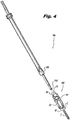
- a driver 700 with a driving end 710 may be passed through the housing bore 23 disposed longitudinally through the housing 20 and through the anvil bore 53 disposed longitudinally through the anvil 50.
- the driver 700 includes a sleeve 720 configured to engage housing 20.
- the driver 700 can transmit torque to the rod reduction device 10 and the bone anchor "B.”
- the user may employ driver 700 to insert the bone anchor "B” into the bone and to reduce the spinal rod “R” into the in the saddle “X” of the bone anchor "B.”
- the user positions the bone anchor "B” close to a bone and places the sleeve 720 over the proximal end 20a of the housing 20. Moreover, the user passes driving end 710 through the housing bore 23 and the anvil bore 53 until the driving end 710 engages a shaft portion "S" of the bone anchor “B.” Then, a torsional force is applied to the driver 700. Upon application of such torsional force, the rod reduction device 10 rotates along with the bone anchor "B” to advance the bone anchor "B” distally into the bone.
- the driver 700 and/or driver tube 800 may be removed and the reduction screw 600 ( FIGS. 2A-2B ) may be inserted through the housing bore 23 ( FIG. 5 ) and the anvil bore 53.
- the reduction screw 600 has a head 610 disposed on the proximal end thereof for driving the reduction screw 600, a threaded portion 620 on the distal end for advancing the reduction screw 600 through the housing bore 23 and the anvil bore 53, and a shoulder 630 positioned distally of the threaded portion 620. From the illustration in FIG.
- the spinal rod “R” may also be introduced between the two arms 130, 140 of the rod reduction device 100 and above the saddle “X" of the bone anchor “B".
- the threads of the reduction screw 600 engage threads on the inside of the housing bore 23 (see Fig. IA) such that when a torsional force is applied to the reduction screw 600 a controlled and measurable incremental linear advancement of the reduction screw 600 occurs.
- the reduction screw 600 passes through the anvil bore 53 until the shoulder 630 engages on the anvil 50. At this point, shoulder 630 rests on the anvil 50 and the reduction screw 600 is ready to drive anvil 50. Further distal advancement of the reduction screw 600 drives anvil 50 distally along the first and second arms 30, 40.
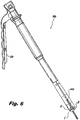
- a locking instrument ( Fig. 6 ) may be placed overtop the entire assembly. Squeezing the lever 810 of the driving tube 800 causes it to engage the bone anchor “B” and pull up on a coupling "C” of the bone anchor “B” while pushing down on the reduction screw 600 and spinal rod “R” thereby fully locking the spinal rod “R” into the bone anchor “B” without applying any force to the patient. Releasing the lever 810 disengages the driving tube 800 from the bone anchor "B” so the driving tube 800 may be removed.
- the reduction screw 600 may then be unscrewed, the anvil 50 retracted and the rod reduction device 10, 100 may be disassembled from the bone anchor "B.”
- the driving tube 800 may fully or partially lock the bone anchor "B” onto the spinal rod “R.”
- the spinal rod “R” may be partially locked (i.e., reducing the spinal rod “R” in the saddle “X” ⁇ the spinal rod “R” can move transverse to the longitudinal axis "L” ⁇ ) or fully locked (i.e., pulling the coupling "C” up to the saddle “X” after the spinal rod “R” is reduced) to the bone anchor "B” in order to facilitate adjustment of adjacent bone anchors "B” along the spinal rod “R.” Constructs having multiple bone anchors "B” along the spinal rod “R” are contemplated.
- the driving tube 800 may be used to lock one or more spinal rods "R” after assembling one or more completed spinal rod “R” and bone anchor “B” constructs. After one or more spinal rods “R” are reduced into one or more bone anchors “B” and adjusted for proper placement, each spinal rod “R” and each bone anchor “B” can be fully locked into place as described hereinabove. Accordingly, each spinal rod “R” and bone anchor “B” construct may be partially or fully locked (individually or collectively) using the driving tube 800 as described hereinabove. Thus, the bone anchor "B” and spinal rod “R” constructs may provide permanent spinal support to the patient.
- the anvil 250 is configured with an anvil post 260 disposed on the distal end thereof.
- the anvil post 260 has a hexalobular distal end 262.
- This embodiment of the rod reduction device 200 allows the anvil 250 to be moved distally to secure the arms 130, 140 to the bone anchor "B' while the hexalobular distal end 262 mates with the screw shank "S" of the bone anchor "B.”
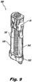
- a driving instrument "D" such as that shown in Figure 8 , may be used to drive the screw shank "S" of the bone anchor "B” into bone from a proximal end of the driving instrument “D.”
- the driving instrument “D” includes a distal end configured to engage the housing 20 and transmit torque to the rod reduction device 300 and to the bone anchor "B” attached to rod reduction device 300.
- the user may implant bone anchor "B” into bone before or after reducing the spinal rod “R” into the bone anchor saddle “X.”
- the user first places the distal end of the driving instrument “D” over the housing 20 and then rotates the driving instrument “D” while advancing the driving instrument “D” distally. During rotation, the distal end of driving instrument “D” transmits the torque to the rod reduction device 300 and the bone anchor "B.” Consequently, the bone anchor "B” is incrementally introduced into the bone.
- the user may reduce spinal rod “R” into the bone anchor saddle "X".
- spinal rod reduction the anvil post 260 of anvil 250 is retracted proximally and a spinal rod “R” is placed between the arms 130, 140 of the rod reduction device 200.
- the user then rotates the reduction screw 600 about longitudinal axis "L,” thereby driving anvil post 260 distally. While the anvil post 260 moves distally, the hexalobular distal end 262 of the anvil post 260 urges the spine rod “R” distally, reducing the spinal rod "R” into the bone anchor "B.”
- rod reduction device 300 includes a reduction screw 310 disposed in mechanical cooperation with the housing 20 and an anvil 350.
- the reduction screw 310 has an engaging spool 320 at a distal end thereof for cooperation with interconnecting pins 330a, 330b and an anvil head 360.
- the engaging spool 320 is substantially cylindrical with an annular channel 322 constructed about the center.
- the anvil 350 has an anvil bore 352 adapted to receive the reduction screw 310 including the engaging spool 320, a thrust bearing 370, and the anvil head 360.
- the engaging spool 320 and anvil head 360 are configured to interconnect, being partially separated by the thrust bearing 370 sandwiched between the underside of the anvil head 360 and the distal end of the engaging spool 320. Furthermore, the engaging spool 320, the anvil head 360 and the anvil 350 are all interconnected via the interconnecting pins 330a, 330b.
- the anvil head 360 has a substantially cylindrical body with a cavity 362 constructed partially therethrough beginning at the proximal end for receiving the thrust bearing 370 and a portion of the engaging spool 320.
- the anvil head 360 has a contoured surface 364 at the distal end.
- the contoured surface 364 has two protrusions 365, 366, both of which are symmetrically disposed transverse to the longitudinal axis "L" and are configured in a spaced apart relation relative to the centerline of the anvil head 360.
- a parabolic channel 367 is defined by the interior walls of the two protrusions 365, 366 and is constructed to engage a spinal rod "R.”
- This contoured surface 364 may be substantially “v-shaped” for providing better contact with the spinal rod "R.”
- the anvil head 360 can have notches 361a, 361b, disposed in the cylindrical wall for interconnecting the engaging spool 320, the anvil head 360, and the anvil 350 via the two interlocking pins 330a, 330b.
- the anvil head 360 may be made from a hard material for limiting deformation and providing increased surface-to-surface contact with the spinal rod "R" (See FIG. 7 ).
- the threads of the reduction screw 310 engage the threads on the inside of the housing bore 23 such that when a torsional force is applied to the reduction screw 310 a controlled and measurable incremental linear advancement of the reduction screw 310 occurs.
- the anvil head 360 connected thereto translates with the anvil 350 until it contacts the spinal rod "R” while simultaneously manipulating the arms 330, 340 into the closed position.
- the parabolic channel 367 defined on the distal surface of the anvil head 362 e.g.
- the v-shaped surface contours the spinal rod "R.”
- the thrust bearing 370 translates the torsional force into thrust force along the longitudinal axis "L” and begins the advancement of the spinal rod “R.” Further advancement of the reduction screw 310 reduces the spinal rod “R” into the bone anchor saddle “X.”
- the proximal surface of the reduction screw 310 may recess below the top surface of the housing 20 about .020 inches. This additional translation enables further compression of the anvil head 362 on the spinal rod "R.”
- a driver tube 800 ( FIG. 6 ) may be removably attached to the housing 20 and a similar torsional force will advance the rod reduction device and bone anchor "B" as a single unit.
- Any number of prior art handles may be attached to the driver 700 or driver tube 800 in order to obtain the necessary mechanical advantage to aid in applying the torsional force. It is contemplated that other techniques and/or instruments known in the art may be utilized to install the bone anchor.
- any of the embodiments of the rod reduction devices disclosed in the present disclosure may be employed to reduce the spinal rod “R” in the saddle “X” of the bone anchor “B.” This spinal rod reduction may occur before or after implanting the bone anchor "B” to a bone.
- the user may utilize driving instrument “D” or any other suitable instrument.
- the user may also reduce the spinal rod "R” with any disclosed rod reduction devices.
- the grasping features 32, 42 of each arm e.g., 30 and 40
- the grasping features 32, 42 of each arm should engage the mating features "M" of the bone anchor "B.”
- the user translates the anvil (e.g., 50 or 250) distally along the first and second arms (e.g., 30 and 40) until the arms reach the closed position, thereby securing the rod reduction device to the bone anchor "B".
- the user places the spinal rod "R" between the first and second arms (e.g., 30 and 40).
- first and second arms e.g., 30 and 40
- anvil e.g., 50
- the spinal rod “R” into the saddle “X” of the bone anchor "R.”
- the user may lock the spinal rod “R” to the bone anchor "B” with a set screw (not shown).
- the user may utilize multiple rod reduction devices (e.g, 100, 200, or 300) in a single surgery to reduce a single spinal rod "R" into multiple bone anchors "R.”
- This spinal rod reduction may occur before or after implanting the bone anchor "B" to a bone.
- the user sequentially secures each rod reduction device to a bone anchor. After or before attaching the rod reduction devices to the bone anchors "B,” the user places the spinal rod "R” between the first and second arms (e.g., 30 and 40) of each rod reduction device.
- each rod reduction device (as discussed above) to selectively reduce portions of the spinal rod “R” into each bone anchor “B.”
- the spinal rod “R” would be reduced into the saddles “X” of each bone anchor “R.”
- the user may sequentially lock the spinal rod “R” to each bone anchor "B” with set screws (not shown)
Landscapes
- Health & Medical Sciences (AREA)
- Orthopedic Medicine & Surgery (AREA)
- Neurology (AREA)
- Life Sciences & Earth Sciences (AREA)
- Surgery (AREA)
- Heart & Thoracic Surgery (AREA)
- Engineering & Computer Science (AREA)
- Biomedical Technology (AREA)
- Nuclear Medicine, Radiotherapy & Molecular Imaging (AREA)
- Medical Informatics (AREA)
- Molecular Biology (AREA)
- Animal Behavior & Ethology (AREA)
- General Health & Medical Sciences (AREA)
- Public Health (AREA)
- Veterinary Medicine (AREA)
- Surgical Instruments (AREA)
- Prostheses (AREA)
Claims (13)
- Dispositif de réduction de tige (10, 100, 200, 300), comprenant :un logement (20) définissant un axe longitudinal (L) ;des premier (30, 130, 330) et second (40, 140, 340) bras s'étendant de manière distale depuis le logement jusqu'aux extrémités distales des premier et second bras, les extrémités distales des premier et second bras étant configurées pour se fixer de manière libérable à un ancrage osseux (B) ; etune enclume (50, 250, 350) comprenant des premier (52) et second (54) alésages pour bras qui s'étendent longitudinalement à travers l'enclume en parallèle, les premier et second bras positionnés dans les premier et second alésages pour bras, respectivement, pour permettre à l'enclume d'être translatée le long des premier et second bras et de l'axe longitudinal pour faciliter l'insertion d'une tige vertébrale (R) dans l'ancrage osseux ;dans lequel l'enclume et chacun des premier et second bras peuvent être positionnés entre une première position et au moins une seconde position lorsque l'enclume est translatée le long des premier et second bras.
- Dispositif de réduction de tige selon la revendication 1, dans lequel les premier et second bras sont parallèles l'un à l'autre dans au moins une position.
- Dispositif de réduction de tige selon l'une quelconque des revendications précédentes, dans lequel les extrémités distales des premier et second bras incluent au moins une caractéristique de préhension (32, 42) pour venir en prise avec l'ancrage osseux.
- Dispositif de réduction de tige selon l'une quelconque des revendications précédentes, dans lequel l'enclume est configurée pour positionner les premier et second bras dans une position parallèle lors du déplacement de l'enclume sur une distance prédéterminée de manière distale à partir du logement.
- Dispositif de réduction de tige selon l'une quelconque des revendications précédentes, dans lequel le logement comprend un alésage de logement (23) s'étendant longitudinalement à travers celui-ci et l'enclume comprend un alésage d'enclume (53, 352) s'étendant longitudinalement à travers celui-ci, l'alésage de logement et l'alésage d'enclume étant configurés pour recevoir un dispositif d'entraînement (700) pour venir en prise avec l'ancrage osseux.
- Dispositif de réduction de tige selon l'une quelconque des revendications précédentes, dans lequel le dispositif de réduction de tige est configuré pour venir en prise avec un dispositif d'entraînement qui fait avancer le dispositif de réduction de tige et l'ancrage osseux dans l'os.
- Dispositif de réduction de tige selon l'une quelconque des revendications précédentes, dans lequel l'enclume inclut un montant d'enclume (260) disposé à l'extrémité distale de l'enclume.
- Dispositif de réduction de tige selon l'une quelconque des revendications précédentes, comprenant en outre une vis de réduction (600, 310) qui fait avancer l'enclume.
- Dispositif de réduction de tige selon la revendication 8, dans lequel la vis de réduction inclut une bobine de mise en prise (320) disposée sur son extrémité distale, dans lequel la bobine de mise en prise est disposée en coopération mécanique avec une tête d'enclume (360).
- Dispositif de réduction de tige selon la revendication 9, dans lequel la tête d'enclume est couplée à la bobine de mise en prise par l'intermédiaire d'au moins une broche d'interconnexion (330a, 330b).
- Dispositif de réduction de tige selon la revendication 9 ou 10, comprenant en outre un palier de butée (370) associé de manière fonctionnelle à la bobine de mise en prise et à la tête d'enclume, le palier de butée étant disposé entre ceux-ci.
- Dispositif de réduction de tige selon la revendication 9, 10 ou 11, dans lequel la tête d'enclume a une surface profilée (364).
- Dispositif de réduction de tige selon l'une quelconque des revendications précédentes, dans lequel le premier et second bras sont reliés de manière articulée au logement.
Applications Claiming Priority (3)
| Application Number | Priority Date | Filing Date | Title |
|---|---|---|---|
| US13164508P | 2008-06-11 | 2008-06-11 | |
| US8695708P | 2008-08-07 | 2008-08-07 | |
| PCT/US2009/047002 WO2009152302A1 (fr) | 2008-06-11 | 2009-06-11 | Dispositif de réduction de tige |
Publications (3)
| Publication Number | Publication Date |
|---|---|
| EP2296568A1 EP2296568A1 (fr) | 2011-03-23 |
| EP2296568A4 EP2296568A4 (fr) | 2013-06-19 |
| EP2296568B1 true EP2296568B1 (fr) | 2018-04-04 |
Family
ID=41417118
Family Applications (1)
| Application Number | Title | Priority Date | Filing Date |
|---|---|---|---|
| EP09763592.4A Active EP2296568B1 (fr) | 2008-06-11 | 2009-06-11 | Dispositif de réduction de tige |
Country Status (6)
| Country | Link |
|---|---|
| US (2) | US8308729B2 (fr) |
| EP (1) | EP2296568B1 (fr) |
| JP (1) | JP5543964B2 (fr) |
| AU (1) | AU2009257412B2 (fr) |
| ES (1) | ES2672778T3 (fr) |
| WO (1) | WO2009152302A1 (fr) |
Families Citing this family (90)
| Publication number | Priority date | Publication date | Assignee | Title |
|---|---|---|---|---|
| US7833250B2 (en) | 2004-11-10 | 2010-11-16 | Jackson Roger P | Polyaxial bone screw with helically wound capture connection |
| US7862587B2 (en) | 2004-02-27 | 2011-01-04 | Jackson Roger P | Dynamic stabilization assemblies, tool set and method |
| US8876868B2 (en) | 2002-09-06 | 2014-11-04 | Roger P. Jackson | Helical guide and advancement flange with radially loaded lip |
| US7621918B2 (en) | 2004-11-23 | 2009-11-24 | Jackson Roger P | Spinal fixation tool set and method |
| US7377923B2 (en) | 2003-05-22 | 2008-05-27 | Alphatec Spine, Inc. | Variable angle spinal screw assembly |
| US7967850B2 (en) | 2003-06-18 | 2011-06-28 | Jackson Roger P | Polyaxial bone anchor with helical capture connection, insert and dual locking assembly |
| US8936623B2 (en) | 2003-06-18 | 2015-01-20 | Roger P. Jackson | Polyaxial bone screw assembly |
| US7766915B2 (en) | 2004-02-27 | 2010-08-03 | Jackson Roger P | Dynamic fixation assemblies with inner core and outer coil-like member |
| US7776067B2 (en) | 2005-05-27 | 2010-08-17 | Jackson Roger P | Polyaxial bone screw with shank articulation pressure insert and method |
| US11419642B2 (en) | 2003-12-16 | 2022-08-23 | Medos International Sarl | Percutaneous access devices and bone anchor assemblies |
| US7527638B2 (en) | 2003-12-16 | 2009-05-05 | Depuy Spine, Inc. | Methods and devices for minimally invasive spinal fixation element placement |
| US7179261B2 (en) | 2003-12-16 | 2007-02-20 | Depuy Spine, Inc. | Percutaneous access devices and bone anchor assemblies |
| US8998952B2 (en) * | 2004-02-17 | 2015-04-07 | Globus Medical, Inc. | Facet joint replacement instruments and methods |
| US8152810B2 (en) | 2004-11-23 | 2012-04-10 | Jackson Roger P | Spinal fixation tool set and method |
| US11241261B2 (en) | 2005-09-30 | 2022-02-08 | Roger P Jackson | Apparatus and method for soft spinal stabilization using a tensionable cord and releasable end structure |
| US7160300B2 (en) | 2004-02-27 | 2007-01-09 | Jackson Roger P | Orthopedic implant rod reduction tool set and method |
| JP2007525274A (ja) | 2004-02-27 | 2007-09-06 | ロジャー・ピー・ジャクソン | 整形外科インプラントロッド整復器具セット及び方法 |
| US8926672B2 (en) | 2004-11-10 | 2015-01-06 | Roger P. Jackson | Splay control closure for open bone anchor |
| US8444681B2 (en) | 2009-06-15 | 2013-05-21 | Roger P. Jackson | Polyaxial bone anchor with pop-on shank, friction fit retainer and winged insert |
| US9168069B2 (en) | 2009-06-15 | 2015-10-27 | Roger P. Jackson | Polyaxial bone anchor with pop-on shank and winged insert with lower skirt for engaging a friction fit retainer |
| WO2006057837A1 (fr) | 2004-11-23 | 2006-06-01 | Jackson Roger P | Structure d'accrochage pour outil de fixation spinale |
| US8100946B2 (en) | 2005-11-21 | 2012-01-24 | Synthes Usa, Llc | Polyaxial bone anchors with increased angulation |
| JP2010512178A (ja) | 2006-12-08 | 2010-04-22 | ロジャー・ピー・ジャクソン | 動的脊椎インプラントのためのツールシステム |
| US8961523B2 (en) | 2007-07-13 | 2015-02-24 | K2M, Inc. | Rod reduction device and method of use |
| US9439681B2 (en) | 2007-07-20 | 2016-09-13 | DePuy Synthes Products, Inc. | Polyaxial bone fixation element |
| WO2009158707A1 (fr) * | 2008-06-27 | 2009-12-30 | K2M, Inc. | Système et procédé de réalisation d'une chirurgie vertébrale |
| WO2010147639A1 (fr) | 2008-08-01 | 2010-12-23 | Jackson Roger P | Élément longitudinal de liaison avec cordons tendus gainés |
| PL2337512T3 (pl) * | 2008-09-12 | 2012-09-28 | Synthes Gmbh | System usztywniający do stabilizacji i kierowania wzrostem kręgosłupa |
| JP2012504029A (ja) | 2008-09-29 | 2012-02-16 | ジンテス ゲゼルシャフト ミット ベシュレンクテル ハフツング | 多軸型底部装填ねじ及びロッドの組立体 |
| EP3117788B1 (fr) | 2008-11-03 | 2020-04-01 | Synthes GmbH | Ensemble fixation osseuse plane |
| FR2937855B1 (fr) | 2008-11-05 | 2010-12-24 | Warsaw Orthopedic Inc | Instrument d'introduction progressive d'une tige vertebrale. |
| KR20120013312A (ko) | 2009-04-15 | 2012-02-14 | 신세스 게엠바하 | 척추 구조물용 교정 커넥터 |
| US8998959B2 (en) | 2009-06-15 | 2015-04-07 | Roger P Jackson | Polyaxial bone anchors with pop-on shank, fully constrained friction fit retainer and lock and release insert |
| WO2013043218A1 (fr) | 2009-06-15 | 2013-03-28 | Jackson Roger P | Dispositif d'ancrage osseux polyaxial doté d'une tige à enclenchement par pression et insert à ailettes à pince de compression à ajustement par friction |
| EP2753252A1 (fr) | 2009-06-15 | 2014-07-16 | Jackson, Roger P. | Ancrage osseux polyaxial avec tige fixée par pression et élément de retenue à ajustement serré doté d'un verrou de bordure discret |
| US11229457B2 (en) | 2009-06-15 | 2022-01-25 | Roger P. Jackson | Pivotal bone anchor assembly with insert tool deployment |
| BRPI1012921A2 (pt) | 2009-06-17 | 2016-04-05 | Synthes Gmbh | conector de revisão para construção espinhal |
| US20150105831A1 (en) * | 2009-10-09 | 2015-04-16 | Synthes Usa, Lla | Tightening device for spine surgery |
| US8545505B2 (en) | 2010-01-15 | 2013-10-01 | Pioneer Surgical Technology, Inc. | Low friction rod persuader |
| US8685029B2 (en) | 2010-09-27 | 2014-04-01 | DePuy Synthes Products, LLC | Rod reduction instrument and methods of rod reduction |
| US20120191144A1 (en) * | 2011-01-26 | 2012-07-26 | Warsaw Orthopedic, Inc | Instrument for reduction of a vertebral rod and method of use |
| US8556904B2 (en) | 2011-05-05 | 2013-10-15 | Warsaw Orthopedic, Inc. | Anchors extender assemblies and methods for using |
| USD649243S1 (en) | 2011-05-05 | 2011-11-22 | Ebi, Llc | Pusher for a rod reduction device |
| US9204909B2 (en) | 2011-07-13 | 2015-12-08 | Warsaw Orthopedic, Inc. | Spinal rod system and method |
| US8932296B2 (en) | 2011-09-27 | 2015-01-13 | Oak Tree Engineering Llc | Spinal rod persuader |
| US9289250B2 (en) * | 2011-10-17 | 2016-03-22 | Warsaw Orthopedic, Inc. | Extender collar system |
| US8911479B2 (en) | 2012-01-10 | 2014-12-16 | Roger P. Jackson | Multi-start closures for open implants |
| US9125703B2 (en) | 2012-01-16 | 2015-09-08 | K2M, Inc. | Rod reducer, compressor, distractor system |
| US9480505B2 (en) * | 2012-08-23 | 2016-11-01 | DePuy Synthes Products, Inc. | Bi-planar persuader |
| US8911478B2 (en) | 2012-11-21 | 2014-12-16 | Roger P. Jackson | Splay control closure for open bone anchor |
| US10058354B2 (en) | 2013-01-28 | 2018-08-28 | Roger P. Jackson | Pivotal bone anchor assembly with frictional shank head seating surfaces |
| US8852239B2 (en) | 2013-02-15 | 2014-10-07 | Roger P Jackson | Sagittal angle screw with integral shank and receiver |
| AU2014201336B2 (en) | 2013-03-11 | 2018-04-19 | K2M, Inc. | Flexible Fastening System |
| US9668789B2 (en) * | 2013-03-15 | 2017-06-06 | Ebi, Llc | Reduction instrument, surgical assembly including a reduction instrument and related method |
| US10136927B1 (en) | 2013-03-15 | 2018-11-27 | Nuvasive, Inc. | Rod reduction assemblies and related methods |
| US9486256B1 (en) | 2013-03-15 | 2016-11-08 | Nuvasive, Inc. | Rod reduction assemblies and related methods |
| US20150100098A1 (en) * | 2013-10-07 | 2015-04-09 | K2M, Inc. | Rod reducer |
| US9452000B2 (en) | 2013-10-07 | 2016-09-27 | K2M, Inc. | Rod reducer |
| US9566092B2 (en) | 2013-10-29 | 2017-02-14 | Roger P. Jackson | Cervical bone anchor with collet retainer and outer locking sleeve |
| AU2014259592B2 (en) | 2013-11-15 | 2019-05-16 | K2M, Inc. | System for corrective spinal surgery and method of use |
| US9717533B2 (en) | 2013-12-12 | 2017-08-01 | Roger P. Jackson | Bone anchor closure pivot-splay control flange form guide and advancement structure |
| US9451993B2 (en) | 2014-01-09 | 2016-09-27 | Roger P. Jackson | Bi-radial pop-on cervical bone anchor |
| US9597119B2 (en) | 2014-06-04 | 2017-03-21 | Roger P. Jackson | Polyaxial bone anchor with polymer sleeve |
| US10064658B2 (en) | 2014-06-04 | 2018-09-04 | Roger P. Jackson | Polyaxial bone anchor with insert guides |
| US9381051B2 (en) | 2014-07-31 | 2016-07-05 | Innovasis, Inc. | Reduction jack for spinal rod placement and method of use |
| US9943344B2 (en) | 2015-01-15 | 2018-04-17 | K2M, Inc. | Rod reducer |
| EP3288473B1 (fr) * | 2015-04-30 | 2022-12-28 | K2M, Inc. | Réducteur à tige |
| US10117678B2 (en) | 2015-05-28 | 2018-11-06 | K2M, Inc. | Surgical system for bone screw insertion and rod reduction |
| AU2016203448B2 (en) * | 2015-05-28 | 2021-02-25 | K2M, Inc. | Surgical system for bone screw insertion and rod reduction |
| US9962191B2 (en) | 2016-01-19 | 2018-05-08 | K2M, Inc. | Spinal implant and methods of use thereof |
| US10524843B2 (en) | 2016-05-06 | 2020-01-07 | K2M, Inc. | Rotation shaft for a rod reducer |
| EP3287088B1 (fr) | 2016-08-24 | 2019-01-09 | Biedermann Technologies GmbH & Co. KG | Instrument destiné à verrouiller et déverrouiller une tête d'un ancrage osseux dans un dispositif d'ancrage osseux polyaxial |
| WO2018071514A1 (fr) | 2016-10-11 | 2018-04-19 | K2M, Inc. | Implant vertébral et procédés d'utilisation de celui-ci |
| US10779866B2 (en) | 2016-12-29 | 2020-09-22 | K2M, Inc. | Rod reducer assembly |
| US10485590B2 (en) | 2017-01-18 | 2019-11-26 | K2M, Inc. | Rod reducing device |
| US10973558B2 (en) | 2017-06-12 | 2021-04-13 | K2M, Inc. | Screw insertion instrument and methods of use |
| US10610269B2 (en) | 2017-09-05 | 2020-04-07 | Medos International Sarl | Modular surgical instruments and related methods |
| US11730522B2 (en) | 2017-10-20 | 2023-08-22 | Spine Wave, Inc. | Threaded spinal rod reducer |
| US10966762B2 (en) | 2017-12-15 | 2021-04-06 | Medos International Sarl | Unilateral implant holders and related methods |
| US11051861B2 (en) | 2018-06-13 | 2021-07-06 | Nuvasive, Inc. | Rod reduction assemblies and related methods |
| US11291482B2 (en) | 2019-03-21 | 2022-04-05 | Medos International Sarl | Rod reducers and related methods |
| USD1004774S1 (en) | 2019-03-21 | 2023-11-14 | Medos International Sarl | Kerrison rod reducer |
| US11291481B2 (en) | 2019-03-21 | 2022-04-05 | Medos International Sarl | Rod reducers and related methods |
| US11553947B2 (en) | 2019-07-16 | 2023-01-17 | Aesculap Implant Systems, Llc | Spinal deformity sequential persuader |
| US12318121B2 (en) | 2020-11-09 | 2025-06-03 | Medos International Sàrl | Biplanar forceps reducers and methods of use |
| US12262927B2 (en) | 2020-12-10 | 2025-04-01 | K2M, Inc. | Screw insertion instrument and methods of use |
| WO2022184798A1 (fr) | 2021-03-05 | 2022-09-09 | Medos International Sarl | Réducteur séquentiel |
| JP2024538403A (ja) | 2021-11-19 | 2024-10-18 | メドス・インターナショナル・エスエイアールエル | 整復係止機構 |
| US11903617B1 (en) | 2022-09-06 | 2024-02-20 | Warsaw Orthopedic, Inc | Spinal implant system and methods of use |
| WO2025076022A1 (fr) * | 2023-10-03 | 2025-04-10 | Orthopediatrics Corp. | Réducteur de tige avec verrou de sangle |
Family Cites Families (20)
| Publication number | Priority date | Publication date | Assignee | Title |
|---|---|---|---|---|
| US5720751A (en) * | 1996-11-27 | 1998-02-24 | Jackson; Roger P. | Tools for use in seating spinal rods in open ended implants |
| US6123707A (en) * | 1999-01-13 | 2000-09-26 | Spinal Concepts, Inc. | Reduction instrument |
| DE60032225T2 (de) | 1999-03-30 | 2007-09-13 | Howmedica Osteonics Corp. | Apparat zur stabilisierung der wirbelsäule |
| US6440133B1 (en) | 2001-07-03 | 2002-08-27 | Sdgi Holdings, Inc. | Rod reducer instruments and methods |
| US6957758B2 (en) | 2001-10-05 | 2005-10-25 | Tyco Healthcare Group, Lp | Tilt top anvil for a surgical fastener device |
| US20040267275A1 (en) * | 2003-06-26 | 2004-12-30 | Cournoyer John R. | Spinal implant holder and rod reduction systems and methods |
| US7090674B2 (en) | 2003-11-03 | 2006-08-15 | Spinal, Llc | Bone fixation system with low profile fastener |
| US8152810B2 (en) * | 2004-11-23 | 2012-04-10 | Jackson Roger P | Spinal fixation tool set and method |
| US7591836B2 (en) | 2004-07-30 | 2009-09-22 | Zimmer Spine, Inc. | Surgical devices and methods for vertebral shifting utilizing spinal fixation systems |
| US7572281B2 (en) * | 2004-08-06 | 2009-08-11 | Depuy Spine, Inc. | Instrument for guiding a rod into an implant in a spinal fixation system |
| US7462182B2 (en) * | 2004-08-10 | 2008-12-09 | Warsaw Orthopedic, Inc. | Reducing instrument for spinal surgery |
| ES2318917B1 (es) | 2005-03-30 | 2010-02-04 | Sdgi Holdings Inc. | Sistema para la correccion tridimensional de la curvatura de la columna vertebral en problemas de escoliosis por alineacion coplanar de los tornillos pediculares. |
| US7988694B2 (en) | 2005-09-29 | 2011-08-02 | K2M, Inc. | Spinal fixation system having locking and unlocking devices for use with a multi-planar, taper lock screw |
| US7655008B2 (en) | 2006-02-09 | 2010-02-02 | Warsaw Orthopedic, Inc. | Methods and instruments for spinal derotation |
| US7927334B2 (en) | 2006-04-11 | 2011-04-19 | Warsaw Orthopedic, Inc. | Multi-directional rod reducer instrument and method |
| US7922749B2 (en) | 2006-04-14 | 2011-04-12 | Warsaw Orthopedic, Inc. | Reducing device |
| US8192438B2 (en) | 2006-05-18 | 2012-06-05 | Phygen, LLC. | Rod reducer |
| US20080015601A1 (en) * | 2006-06-14 | 2008-01-17 | Michael Castro | Reduction device and method of use |
| US8961523B2 (en) | 2007-07-13 | 2015-02-24 | K2M, Inc. | Rod reduction device and method of use |
| EP2296569B1 (fr) * | 2008-06-11 | 2014-04-09 | K2M, Inc. | Dispositif de réduction de tige |
-
2009
- 2009-06-11 JP JP2011513680A patent/JP5543964B2/ja not_active Expired - Fee Related
- 2009-06-11 AU AU2009257412A patent/AU2009257412B2/en active Active
- 2009-06-11 EP EP09763592.4A patent/EP2296568B1/fr active Active
- 2009-06-11 WO PCT/US2009/047002 patent/WO2009152302A1/fr not_active Ceased
- 2009-06-11 US US12/996,874 patent/US8308729B2/en active Active
- 2009-06-11 ES ES09763592.4T patent/ES2672778T3/es active Active
-
2012
- 2012-10-19 US US13/655,614 patent/US9247969B2/en active Active
Non-Patent Citations (1)
| Title |
|---|
| None * |
Also Published As
| Publication number | Publication date |
|---|---|
| AU2009257412A1 (en) | 2009-12-17 |
| ES2672778T3 (es) | 2018-06-18 |
| JP5543964B2 (ja) | 2014-07-09 |
| EP2296568A4 (fr) | 2013-06-19 |
| JP2011524198A (ja) | 2011-09-01 |
| WO2009152302A1 (fr) | 2009-12-17 |
| AU2009257412B2 (en) | 2014-08-14 |
| US20130046344A1 (en) | 2013-02-21 |
| US8308729B2 (en) | 2012-11-13 |
| EP2296568A1 (fr) | 2011-03-23 |
| US20110118791A1 (en) | 2011-05-19 |
| US9247969B2 (en) | 2016-02-02 |
Similar Documents
| Publication | Publication Date | Title |
|---|---|---|
| EP2296568B1 (fr) | Dispositif de réduction de tige | |
| US12569282B2 (en) | Tissue retraction and vertebral displacement devices, systems, and methods for posterior spinal fusion | |
| US11903621B2 (en) | Rod reduction device and method of use | |
| EP2296569B1 (fr) | Dispositif de réduction de tige | |
| WO2005041799A1 (fr) | Systeme et procede de stabilisation de structures internes | |
| EP3097879B1 (fr) | Système chirurgical pour insertion de vis osseuse et réduction de tige |
Legal Events
| Date | Code | Title | Description |
|---|---|---|---|
| PUAI | Public reference made under article 153(3) epc to a published international application that has entered the european phase |
Free format text: ORIGINAL CODE: 0009012 |
|
| 17P | Request for examination filed |
Effective date: 20110103 |
|
| AK | Designated contracting states |
Kind code of ref document: A1 Designated state(s): AT BE BG CH CY CZ DE DK EE ES FI FR GB GR HR HU IE IS IT LI LT LU LV MC MK MT NL NO PL PT RO SE SI SK TR |
|
| AX | Request for extension of the european patent |
Extension state: AL BA RS |
|
| DAX | Request for extension of the european patent (deleted) | ||
| A4 | Supplementary search report drawn up and despatched |
Effective date: 20130517 |
|
| RIC1 | Information provided on ipc code assigned before grant |
Ipc: A61B 17/70 20060101AFI20130513BHEP |
|
| GRAP | Despatch of communication of intention to grant a patent |
Free format text: ORIGINAL CODE: EPIDOSNIGR1 |
|
| INTG | Intention to grant announced |
Effective date: 20171211 |
|
| GRAS | Grant fee paid |
Free format text: ORIGINAL CODE: EPIDOSNIGR3 |
|
| GRAA | (expected) grant |
Free format text: ORIGINAL CODE: 0009210 |
|
| RAP1 | Party data changed (applicant data changed or rights of an application transferred) |
Owner name: K2M, INC. |
|
| AK | Designated contracting states |
Kind code of ref document: B1 Designated state(s): AT BE BG CH CY CZ DE DK EE ES FI FR GB GR HR HU IE IS IT LI LT LU LV MC MK MT NL NO PL PT RO SE SI SK TR |
|
| REG | Reference to a national code |
Ref country code: GB Ref legal event code: FG4D |
|
| REG | Reference to a national code |
Ref country code: CH Ref legal event code: EP |
|
| REG | Reference to a national code |
Ref country code: AT Ref legal event code: REF Ref document number: 984715 Country of ref document: AT Kind code of ref document: T Effective date: 20180415 |
|
| REG | Reference to a national code |
Ref country code: DE Ref legal event code: R096 Ref document number: 602009051622 Country of ref document: DE |
|
| REG | Reference to a national code |
Ref country code: IE Ref legal event code: FG4D |
|
| REG | Reference to a national code |
Ref country code: FR Ref legal event code: PLFP Year of fee payment: 10 |
|
| REG | Reference to a national code |
Ref country code: ES Ref legal event code: FG2A Ref document number: 2672778 Country of ref document: ES Kind code of ref document: T3 Effective date: 20180618 |
|
| REG | Reference to a national code |
Ref country code: NL Ref legal event code: MP Effective date: 20180404 |
|
| REG | Reference to a national code |
Ref country code: LT Ref legal event code: MG4D |
|
| PG25 | Lapsed in a contracting state [announced via postgrant information from national office to epo] |
Ref country code: NL Free format text: LAPSE BECAUSE OF FAILURE TO SUBMIT A TRANSLATION OF THE DESCRIPTION OR TO PAY THE FEE WITHIN THE PRESCRIBED TIME-LIMIT Effective date: 20180404 |
|
| PG25 | Lapsed in a contracting state [announced via postgrant information from national office to epo] |
Ref country code: PL Free format text: LAPSE BECAUSE OF FAILURE TO SUBMIT A TRANSLATION OF THE DESCRIPTION OR TO PAY THE FEE WITHIN THE PRESCRIBED TIME-LIMIT Effective date: 20180404 Ref country code: SE Free format text: LAPSE BECAUSE OF FAILURE TO SUBMIT A TRANSLATION OF THE DESCRIPTION OR TO PAY THE FEE WITHIN THE PRESCRIBED TIME-LIMIT Effective date: 20180404 Ref country code: FI Free format text: LAPSE BECAUSE OF FAILURE TO SUBMIT A TRANSLATION OF THE DESCRIPTION OR TO PAY THE FEE WITHIN THE PRESCRIBED TIME-LIMIT Effective date: 20180404 Ref country code: BG Free format text: LAPSE BECAUSE OF FAILURE TO SUBMIT A TRANSLATION OF THE DESCRIPTION OR TO PAY THE FEE WITHIN THE PRESCRIBED TIME-LIMIT Effective date: 20180704 Ref country code: NO Free format text: LAPSE BECAUSE OF FAILURE TO SUBMIT A TRANSLATION OF THE DESCRIPTION OR TO PAY THE FEE WITHIN THE PRESCRIBED TIME-LIMIT Effective date: 20180704 Ref country code: LT Free format text: LAPSE BECAUSE OF FAILURE TO SUBMIT A TRANSLATION OF THE DESCRIPTION OR TO PAY THE FEE WITHIN THE PRESCRIBED TIME-LIMIT Effective date: 20180404 |
|
| PG25 | Lapsed in a contracting state [announced via postgrant information from national office to epo] |
Ref country code: HR Free format text: LAPSE BECAUSE OF FAILURE TO SUBMIT A TRANSLATION OF THE DESCRIPTION OR TO PAY THE FEE WITHIN THE PRESCRIBED TIME-LIMIT Effective date: 20180404 Ref country code: GR Free format text: LAPSE BECAUSE OF FAILURE TO SUBMIT A TRANSLATION OF THE DESCRIPTION OR TO PAY THE FEE WITHIN THE PRESCRIBED TIME-LIMIT Effective date: 20180705 Ref country code: LV Free format text: LAPSE BECAUSE OF FAILURE TO SUBMIT A TRANSLATION OF THE DESCRIPTION OR TO PAY THE FEE WITHIN THE PRESCRIBED TIME-LIMIT Effective date: 20180404 |
|
| REG | Reference to a national code |
Ref country code: AT Ref legal event code: MK05 Ref document number: 984715 Country of ref document: AT Kind code of ref document: T Effective date: 20180404 |
|
| PG25 | Lapsed in a contracting state [announced via postgrant information from national office to epo] |
Ref country code: PT Free format text: LAPSE BECAUSE OF FAILURE TO SUBMIT A TRANSLATION OF THE DESCRIPTION OR TO PAY THE FEE WITHIN THE PRESCRIBED TIME-LIMIT Effective date: 20180806 |
|
| REG | Reference to a national code |
Ref country code: DE Ref legal event code: R097 Ref document number: 602009051622 Country of ref document: DE |
|
| PG25 | Lapsed in a contracting state [announced via postgrant information from national office to epo] |
Ref country code: CZ Free format text: LAPSE BECAUSE OF FAILURE TO SUBMIT A TRANSLATION OF THE DESCRIPTION OR TO PAY THE FEE WITHIN THE PRESCRIBED TIME-LIMIT Effective date: 20180404 Ref country code: RO Free format text: LAPSE BECAUSE OF FAILURE TO SUBMIT A TRANSLATION OF THE DESCRIPTION OR TO PAY THE FEE WITHIN THE PRESCRIBED TIME-LIMIT Effective date: 20180404 Ref country code: SK Free format text: LAPSE BECAUSE OF FAILURE TO SUBMIT A TRANSLATION OF THE DESCRIPTION OR TO PAY THE FEE WITHIN THE PRESCRIBED TIME-LIMIT Effective date: 20180404 Ref country code: DK Free format text: LAPSE BECAUSE OF FAILURE TO SUBMIT A TRANSLATION OF THE DESCRIPTION OR TO PAY THE FEE WITHIN THE PRESCRIBED TIME-LIMIT Effective date: 20180404 Ref country code: EE Free format text: LAPSE BECAUSE OF FAILURE TO SUBMIT A TRANSLATION OF THE DESCRIPTION OR TO PAY THE FEE WITHIN THE PRESCRIBED TIME-LIMIT Effective date: 20180404 Ref country code: AT Free format text: LAPSE BECAUSE OF FAILURE TO SUBMIT A TRANSLATION OF THE DESCRIPTION OR TO PAY THE FEE WITHIN THE PRESCRIBED TIME-LIMIT Effective date: 20180404 |
|
| REG | Reference to a national code |
Ref country code: CH Ref legal event code: PL |
|
| PLBE | No opposition filed within time limit |
Free format text: ORIGINAL CODE: 0009261 |
|
| STAA | Information on the status of an ep patent application or granted ep patent |
Free format text: STATUS: NO OPPOSITION FILED WITHIN TIME LIMIT |
|
| REG | Reference to a national code |
Ref country code: BE Ref legal event code: MM Effective date: 20180630 |
|
| 26N | No opposition filed |
Effective date: 20190107 |
|
| REG | Reference to a national code |
Ref country code: IE Ref legal event code: MM4A |
|
| PG25 | Lapsed in a contracting state [announced via postgrant information from national office to epo] |
Ref country code: MC Free format text: LAPSE BECAUSE OF FAILURE TO SUBMIT A TRANSLATION OF THE DESCRIPTION OR TO PAY THE FEE WITHIN THE PRESCRIBED TIME-LIMIT Effective date: 20180404 Ref country code: LU Free format text: LAPSE BECAUSE OF NON-PAYMENT OF DUE FEES Effective date: 20180611 |
|
| PG25 | Lapsed in a contracting state [announced via postgrant information from national office to epo] |
Ref country code: LI Free format text: LAPSE BECAUSE OF NON-PAYMENT OF DUE FEES Effective date: 20180630 Ref country code: IE Free format text: LAPSE BECAUSE OF NON-PAYMENT OF DUE FEES Effective date: 20180611 Ref country code: CH Free format text: LAPSE BECAUSE OF NON-PAYMENT OF DUE FEES Effective date: 20180630 |
|
| PG25 | Lapsed in a contracting state [announced via postgrant information from national office to epo] |
Ref country code: BE Free format text: LAPSE BECAUSE OF NON-PAYMENT OF DUE FEES Effective date: 20180630 Ref country code: SI Free format text: LAPSE BECAUSE OF FAILURE TO SUBMIT A TRANSLATION OF THE DESCRIPTION OR TO PAY THE FEE WITHIN THE PRESCRIBED TIME-LIMIT Effective date: 20180404 |
|
| PG25 | Lapsed in a contracting state [announced via postgrant information from national office to epo] |
Ref country code: MT Free format text: LAPSE BECAUSE OF NON-PAYMENT OF DUE FEES Effective date: 20180611 |
|
| PG25 | Lapsed in a contracting state [announced via postgrant information from national office to epo] |
Ref country code: TR Free format text: LAPSE BECAUSE OF FAILURE TO SUBMIT A TRANSLATION OF THE DESCRIPTION OR TO PAY THE FEE WITHIN THE PRESCRIBED TIME-LIMIT Effective date: 20180404 |
|
| PG25 | Lapsed in a contracting state [announced via postgrant information from national office to epo] |
Ref country code: HU Free format text: LAPSE BECAUSE OF FAILURE TO SUBMIT A TRANSLATION OF THE DESCRIPTION OR TO PAY THE FEE WITHIN THE PRESCRIBED TIME-LIMIT; INVALID AB INITIO Effective date: 20090611 |
|
| PG25 | Lapsed in a contracting state [announced via postgrant information from national office to epo] |
Ref country code: CY Free format text: LAPSE BECAUSE OF FAILURE TO SUBMIT A TRANSLATION OF THE DESCRIPTION OR TO PAY THE FEE WITHIN THE PRESCRIBED TIME-LIMIT Effective date: 20180404 Ref country code: MK Free format text: LAPSE BECAUSE OF NON-PAYMENT OF DUE FEES Effective date: 20180404 |
|
| PG25 | Lapsed in a contracting state [announced via postgrant information from national office to epo] |
Ref country code: IS Free format text: LAPSE BECAUSE OF FAILURE TO SUBMIT A TRANSLATION OF THE DESCRIPTION OR TO PAY THE FEE WITHIN THE PRESCRIBED TIME-LIMIT Effective date: 20180804 |
|
| PGFP | Annual fee paid to national office [announced via postgrant information from national office to epo] |
Ref country code: IT Payment date: 20220510 Year of fee payment: 14 |
|
| PGFP | Annual fee paid to national office [announced via postgrant information from national office to epo] |
Ref country code: ES Payment date: 20220705 Year of fee payment: 14 |
|
| REG | Reference to a national code |
Ref country code: FR Ref legal event code: PLFP Year of fee payment: 15 |
|
| P01 | Opt-out of the competence of the unified patent court (upc) registered |
Effective date: 20230522 |
|
| REG | Reference to a national code |
Ref country code: ES Ref legal event code: FD2A Effective date: 20240730 |
|
| PG25 | Lapsed in a contracting state [announced via postgrant information from national office to epo] |
Ref country code: IT Free format text: LAPSE BECAUSE OF NON-PAYMENT OF DUE FEES Effective date: 20230611 |
|
| PG25 | Lapsed in a contracting state [announced via postgrant information from national office to epo] |
Ref country code: ES Free format text: LAPSE BECAUSE OF NON-PAYMENT OF DUE FEES Effective date: 20230612 |
|
| PG25 | Lapsed in a contracting state [announced via postgrant information from national office to epo] |
Ref country code: ES Free format text: LAPSE BECAUSE OF NON-PAYMENT OF DUE FEES Effective date: 20230612 |
|
| PGFP | Annual fee paid to national office [announced via postgrant information from national office to epo] |
Ref country code: DE Payment date: 20250402 Year of fee payment: 17 |
|
| PGFP | Annual fee paid to national office [announced via postgrant information from national office to epo] |
Ref country code: GB Payment date: 20250401 Year of fee payment: 17 |
|
| PGFP | Annual fee paid to national office [announced via postgrant information from national office to epo] |
Ref country code: FR Payment date: 20250401 Year of fee payment: 17 |