EP2296745B1 - Ultraschall-geführter roboter zur flexiblen nadelsteuerung - Google Patents
Ultraschall-geführter roboter zur flexiblen nadelsteuerung Download PDFInfo
- Publication number
- EP2296745B1 EP2296745B1 EP09754349.0A EP09754349A EP2296745B1 EP 2296745 B1 EP2296745 B1 EP 2296745B1 EP 09754349 A EP09754349 A EP 09754349A EP 2296745 B1 EP2296745 B1 EP 2296745B1
- Authority
- EP
- European Patent Office
- Prior art keywords
- needle
- tissue
- tip
- ultrasound
- region
- Prior art date
- Legal status (The legal status is an assumption and is not a legal conclusion. Google has not performed a legal analysis and makes no representation as to the accuracy of the status listed.)
- Active
Links
Images


Classifications
-
- A—HUMAN NECESSITIES
- A61—MEDICAL OR VETERINARY SCIENCE; HYGIENE
- A61B—DIAGNOSIS; SURGERY; IDENTIFICATION
- A61B90/00—Instruments, implements or accessories specially adapted for surgery or diagnosis and not covered by any of the groups A61B1/00 - A61B50/00, e.g. for luxation treatment or for protecting wound edges
- A61B90/10—Instruments, implements or accessories specially adapted for surgery or diagnosis and not covered by any of the groups A61B1/00 - A61B50/00, e.g. for luxation treatment or for protecting wound edges for stereotaxic surgery, e.g. frame-based stereotaxis
- A61B90/11—Instruments, implements or accessories specially adapted for surgery or diagnosis and not covered by any of the groups A61B1/00 - A61B50/00, e.g. for luxation treatment or for protecting wound edges for stereotaxic surgery, e.g. frame-based stereotaxis with guides for needles or instruments, e.g. arcuate slides or ball joints
-
- A—HUMAN NECESSITIES
- A61—MEDICAL OR VETERINARY SCIENCE; HYGIENE
- A61B—DIAGNOSIS; SURGERY; IDENTIFICATION
- A61B17/00—Surgical instruments, devices or methods
- A61B17/34—Trocars; Puncturing needles
- A61B17/3403—Needle locating or guiding means
-
- A—HUMAN NECESSITIES
- A61—MEDICAL OR VETERINARY SCIENCE; HYGIENE
- A61B—DIAGNOSIS; SURGERY; IDENTIFICATION
- A61B34/00—Computer-aided surgery; Manipulators or robots specially adapted for use in surgery
- A61B34/20—Surgical navigation systems; Devices for tracking or guiding surgical instruments, e.g. for frameless stereotaxis
-
- A—HUMAN NECESSITIES
- A61—MEDICAL OR VETERINARY SCIENCE; HYGIENE
- A61B—DIAGNOSIS; SURGERY; IDENTIFICATION
- A61B34/00—Computer-aided surgery; Manipulators or robots specially adapted for use in surgery
- A61B34/30—Surgical robots
-
- A—HUMAN NECESSITIES
- A61—MEDICAL OR VETERINARY SCIENCE; HYGIENE
- A61B—DIAGNOSIS; SURGERY; IDENTIFICATION
- A61B8/00—Diagnosis using ultrasonic, sonic or infrasonic waves
- A61B8/48—Diagnostic techniques
- A61B8/485—Diagnostic techniques involving measuring strain or elastic properties
-
- A—HUMAN NECESSITIES
- A61—MEDICAL OR VETERINARY SCIENCE; HYGIENE
- A61B—DIAGNOSIS; SURGERY; IDENTIFICATION
- A61B17/00—Surgical instruments, devices or methods
- A61B17/34—Trocars; Puncturing needles
- A61B17/3403—Needle locating or guiding means
- A61B2017/3405—Needle locating or guiding means using mechanical guide means
- A61B2017/3409—Needle locating or guiding means using mechanical guide means including needle or instrument drives
-
- A—HUMAN NECESSITIES
- A61—MEDICAL OR VETERINARY SCIENCE; HYGIENE
- A61B—DIAGNOSIS; SURGERY; IDENTIFICATION
- A61B17/00—Surgical instruments, devices or methods
- A61B17/34—Trocars; Puncturing needles
- A61B17/3403—Needle locating or guiding means
- A61B2017/3413—Needle locating or guiding means guided by ultrasound
-
- A—HUMAN NECESSITIES
- A61—MEDICAL OR VETERINARY SCIENCE; HYGIENE
- A61B—DIAGNOSIS; SURGERY; IDENTIFICATION
- A61B34/00—Computer-aided surgery; Manipulators or robots specially adapted for use in surgery
- A61B34/10—Computer-aided planning, simulation or modelling of surgical operations
- A61B2034/107—Visualisation of planned trajectories or target regions
-
- A—HUMAN NECESSITIES
- A61—MEDICAL OR VETERINARY SCIENCE; HYGIENE
- A61B—DIAGNOSIS; SURGERY; IDENTIFICATION
- A61B34/00—Computer-aided surgery; Manipulators or robots specially adapted for use in surgery
- A61B34/20—Surgical navigation systems; Devices for tracking or guiding surgical instruments, e.g. for frameless stereotaxis
- A61B2034/2046—Tracking techniques
- A61B2034/2063—Acoustic tracking systems, e.g. using ultrasound
-
- A—HUMAN NECESSITIES
- A61—MEDICAL OR VETERINARY SCIENCE; HYGIENE
- A61B—DIAGNOSIS; SURGERY; IDENTIFICATION
- A61B34/00—Computer-aided surgery; Manipulators or robots specially adapted for use in surgery
- A61B34/20—Surgical navigation systems; Devices for tracking or guiding surgical instruments, e.g. for frameless stereotaxis
- A61B2034/2046—Tracking techniques
- A61B2034/2065—Tracking using image or pattern recognition
-
- A—HUMAN NECESSITIES
- A61—MEDICAL OR VETERINARY SCIENCE; HYGIENE
- A61B—DIAGNOSIS; SURGERY; IDENTIFICATION
- A61B34/00—Computer-aided surgery; Manipulators or robots specially adapted for use in surgery
- A61B34/30—Surgical robots
- A61B2034/301—Surgical robots for introducing or steering flexible instruments inserted into the body, e.g. catheters or endoscopes
-
- A—HUMAN NECESSITIES
- A61—MEDICAL OR VETERINARY SCIENCE; HYGIENE
- A61B—DIAGNOSIS; SURGERY; IDENTIFICATION
- A61B90/00—Instruments, implements or accessories specially adapted for surgery or diagnosis and not covered by any of the groups A61B1/00 - A61B50/00, e.g. for luxation treatment or for protecting wound edges
- A61B90/36—Image-producing devices or illumination devices not otherwise provided for
- A61B90/37—Surgical systems with images on a monitor during operation
- A61B2090/378—Surgical systems with images on a monitor during operation using ultrasound
Definitions
- This method used for closed-loop needle insertion, utilizes an algorithm for robotic maneuvering of the needle base, based on a virtual spring model, path planning, needle tip and profile detection, and an iterative estimation of tissue stiffness by analyzing the displacement of the tissue along the length of the needle as a result of forces applied by the needle on the tissue.
- each segment i is subjected to point forces, F i , which depend on the local displacement w i , from the initial position, w oi , and the tissue stiffness, described by the virtual spring coefficient, k i .
- the X-ray fluoroscope tracking described in the prior art involves X-radiation doses to the subject, and incidental scattered radiation exposure to the medical personnel performing the procedure. Additionally, availability of an X-ray system for performing the imaging may be limited, and such equipment is expensive, such that an alternative method of tracking the needle would be desirable.
- This disclosure describes a system according to the invention and a method not according to the present invention for steering a flexible needle in a soft tissue under the real time guidance of ultrasound imaging.
- the use of ultrasound provides advantages over other imaging modalities.
- the main advantages over the use of X-ray imaging are the absence of radiation hazard, more general availability and lower cost.
- the cumulative path of the needle can be determined to a first order approximation by the graphic process of joining these needle tip positions. This path is approximate since it does not take into account any lateral motion of the needle path in proximal sections of the needle as the distal needle tip proceeds further into the tissue. However, it does mean that the entire beam configuration is known in the form of the tissue stiffness at all the incremental points along the length of the known needle path. Although this information is not needed for performing the first order iterative insertion process described in this disclosure, it may be useful in any derivative measurements which may be performed.
- this "deep tissue elastography" may be used to determine pathological data about tissue, which would otherwise be difficult to discern from prior art elastography procedures performed by application of external forces at the surface of the tissue.
- One example implementation of the systems described in this disclosure involves a system for controlling the insertion of a flexible needle having a tip, into a tissue according to a predetermined trajectory, in which the system comprises:
- the inverse kinematic solution may be performed on a model of the needle as a flexible beam having a plurality of virtual springs connected laterally thereto to simulate lateral forces exerted by the tissue on the needle, and the lateral forces exerted by the tissue on the needle may be determined from the elastic properties of the tissue derived from the displacement pattern around the needle tip.
- the path of the model of the needle through the tissue may be determined by the influence of the plurality of virtual springs on the needle.
- An alternative exemplary system for the insertion of such a a flexible needle into a tissue according to a predetermined trajectory may comprise:
- the path of the model of the needle through the tissue may be determined by the influence of the plurality of virtual springs on the needle. Additionally, the control system may further utilize an inverse kinematics solution applied to the virtual springs model to calculate the required motion to be imparted to the needle such that the tip follows the planned trajectory.
- the predetermined trajectory of the needle may comprise a target for the tip of the needle and at least one region which should be avoided by the needle.
- the systems may further comprise a force sensor to determine the forces exerted on the needle at its base, in which case the control system also uses the measured forces to determine stiffness properties of the tissue in the vicinity of the needle tip.
- control system may determine the deviation of the position of the tip determined by image processing of an ultrasound image, from the planned position of the tip according to the predetermined trajectory, and calculates the motion to be applied to the robot to reduce the deviation.
- the predetermined trajectory may be divided into increments, and the control system may perform the insertion according to these increments in accordance with the real time position of the needle tip obtained from the ultrasound imaging system at each incremental insertion point. Furthermore, the predetermined trajectory may be selected to avoid passage through undesired regions of the tissue.
- Still other example implementations involve a method for determining the elastic characteristics of a tissue, comprising:
- Such a method may further comprise the step of measuring the force applied externally during insertion of the needle, and using the force measurement to determine the elastic characteristics of the tissue in the region of the tip.
- the nature of the displacement pattern may include at least one of the magnitude and the form of the displacements in the pattern.
- the elastic characteristics of the tissue may be utilized to detect pathological anomalies in the tissue.
- Still further exemplary implementations involve a system for determining the elastic characteristics of a tissue, the system comprising:
- Such a system may further comprise a force sensor for measuring the insertion force applied to the needle, wherein the force measurement may be used to increase the accuracy of the determining the elastic characteristics of the tissue in the region of the tip.
- the nature of the displacement pattern may include at least one of the magnitude and the form of the displacements in the pattern. Additionally, the elastic characteristics of the tissue determined using such a system may be utilized to detect pathological anomalies in the tissue.
- Another exemplary implementation of the systems described herewithin may further involve a system for controlling the insertion of a flexible needle having a tip, into a tissue according to a predetermined trajectory, the system comprising:
- the inverse kinematic solution may be performed on a model of the needle as a flexible beam having a plurality of virtual springs connected laterally thereto to simulate lateral forces exerted by the tissue on the needle, and the lateral forces exerted by the tissue on the needle may be determined from the elastic properties of the tissue derived from the displacement pattern around the needle.
- Yet a further exemplary implementation of the systems described herewithin may involve a system for the insertion of a flexible needle having a tip into a tissue, according to a predetermined trajectory, the system comprising:
- the path of the model of the needle through the tissue may be determined by the influence of the plurality of virtual springs on the needle.
- the control system may utilize an inverse kinematics solution applied to the virtual springs model to calculate the required motion to be imparted to the needle such that the tip follows the planned trajectory.
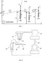
- Fig. 2 is a schematic illustration of an exemplary system for performing the controlled needle insertion methods described in this application.
- the flexible needle 24 is shown held in the insertion robot 25 and the insertion progress into the subject's tissue 20 is shown being monitored by an ultrasound (US) imaging system, including the ultrasound probe 22 and its control and display system 23.
- the probe may generally incorporate both the ultrasound transducer and the sensor system for the US energy returned from the needle and tissue.
- the US control system 23 may generally include the US power supply and the signal processing routines for analyzing the signals received and for generating the US image therefrom.
- the robot 25 used for holding the needle 24, and for aligning and propelling it into the patient's tissue 20 may be an RSPR 6DOF parallel robot, such as that described in the article entitled " Image-guided Robot for Flexible Needle Steering", by D. Glozman and M. Shoham, published in IEEE Transactions on Robotics, Vol. 23, No. 3, June 2007 . It is to be understood though, that the systems described herein are not meant to be limited to use of a parallel robot structure, but that any serial, parallel or hybrid robotic structure may be used.
- the robot motion may be controlled by means of its control system 27.
- the needle may be connected to the robot's moving plate by a 6-DOF force/torque transducer 26, which measures needle insertion forces and torques.
- a separate control system 28 for performing the calculations of the needle motion control algorithm and for running the motion control loop. Its function is to obtain the required needle base coordinates for each insertion step, and to issue commands to the robot so that it moves the needle base to the requested coordinates after calculation of each step of the inverse kinetics equation.
- the control loop is responsible for receiving incoming data from the US image processing system computer 23, and to generate movement commands based on that data.
- the raw US data or the US image may be analyzed in order to define the needle tip position, the needle path shape, data related to the tissue elastic characteristics, and insertion force information from the force sensor, for input to the robot control system. This may be performed in the system control computer 28, which may be responsible for the image processing, needle and tissue detections as well as needle control.
- the system computer 28 commands the motions of the robot via the robot control computer 27. Communication between the two can be provided by a data link 29.
- Needle visibility in an ultrasound image depends on several parameters: needle diameter, needle coating, insertion angle and most importantly the alignment of the ultrasound probe plane with the needle, as described in the article entitled " Ultrasound visibility of needles used for regional nerve block: An in vitro study" by I. Schafhalter-Zoppoth et al, published in Reg Anesth Pain Med 2004; Vol. 29, pp.480-488 .
- the probe alignment may be achieved by using a digitizer, such as the MicroScribe 3DXL digitizer, available from Immersion Products Inc. of San Jose, CA, calibrated to the robot's coordinate system. The digitizer may then be used to align the ultrasound probe central axis plane to the needle.
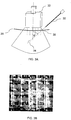
- FIG. 3A illustrates schematically a needle 30 being inserted into a tissue 20 at an angle 0 to the direction of ultrasound imaging beam emitted from the US probe 32.
- the needle is directed from the point of insertion 36, into the tissue 20 towards the target point 34.
- the needle shaft may be seen along most of its length, but the needle tip is not clearly visible.
- the needle tip becomes clearly visible in the US image, as a bright area which moves as the needle advances. This is clearly seen in the example of an ultrasound image shown in Fig. 3B , where the position of the needle tip is indicated by the arrow.
- Figs. 4A to 4C show methods of detecting the needle tip in the ultrasound images. Because of the high level of speckle in the US images, it is not always easy to use image processing directly on the US image to determine the position of the needle tip.
- the needle tip is seen in Fig. 4A as a bright area. Since, as the needle tip advances, for the close to normal alignment angles used, the main difference from frame to frame is needle tip position, the needle tip can be easily detected by the simple image processing procedure of subtraction of the current frame from a reference frame.
- Fig. 4B is such a reference frame, taken of the immediately preceding step to that of Fig. 4A , as evidenced by the time stamp on the image. Subtraction of the reference frame of Fig.
- Fig. 4C the image shown in Fig. 4C , where only the needle tip, marked with a white arrow, is seen as a bright area, since it is the only object that changes between the two frames.
- the image of Fig. 4C is cropped to leave just the tip region, and a threshold is applied to this cropped area.
- the tip position is considered as the center of the mass of the largest bright area above the threshold level in the difference image.
- image to probe registration is applied, and probe to robot transformation is measured using a digitizer. Using this image-robot registration, the detected needle tip position in the image can be expressed in the robot's coordinate system.
- the deviation of the position of the tip from the desired path is then used in the next insertion step, with the magnitude and angle of the needle base insertion being determined by the controller.
- Knowing the tissue's stiffness is required for accurate calculation of the inverse kinematics problem. Since there is no a priori knowledge of the tissue properties all the way through from the needle insertion point to the target area, and since using ultrasound, the needle path cannot be used to iteratively estimate the tissue stiffness, a novel method is described in this disclosure for estimating the tissue properties. The method used is based on ultrasound elastography which derives elastic properties of soft tissue from measurement of tissue displacement under the effects of applied forces. Ultrasonic imaging is a common medical imaging technique for producing elastograms.
- tracking the movement of the speckle-pattern in the ultrasound image may be based on the bilinear deformable block matching algorithm, as proposed in the article by A. Basarab, et al, entitled “A method for vector displacement estimation with ultrasound imaging and its application for thyroid nodular disease", published in Medical Image Analysis, Vol. 12, No. 3, June 2008, pp. 259-274 , and prepublished on-line in October 2007 as Med. Image Anal. (2007), doi:10.1016/ j.media.2007.10.007 .
- a bilinear deformable block matching algorithm is only one technique by which the image movements may be extracted, and the methods of the present disclosure are not intended to be limited just to this described method.
- the objective of elastography is to estimate tissue motion between a pair of ultrasound images: a reference frame before deformation, and a comparison frame, after tissue deformation, which is due to the needle movement.
- the reference frame is first divided into regions of interest around defined nodes placed in front of the needle tip. This is shown in the ultrasound image shown in Fig. 5 , where the regions of interest are shown as overlapping white rectangles having twice the lateral dimensions as the axial dimension, around the defined nodes, shown as small black crosses.
- the measured position of the needle tip is shown as a solitary black cross.
- a suitable size is 2.2 mm in the axial direction and 5.6 mm in the lateral direction.
- Defining overlapping regions of interest increases the accuracy of displacement estimation.
- the regions of interest may advantageously be arranged with an overlap of 60% in the lateral axis and 50% in the axial axis.
- the translation of the corners of each ROI is then calculated by a single level block matching algorithm.
- the block matching criterion is determined by minimizing the sum of squared difference (SSD).
- the displacement for all pixels inside the ROI are calculated based on a bilinear model.
- the unknown bilinear parameters can be found from the calculated displacement of the corners.
- a calibration scale or a look-up table can be generated which enables the estimated stiffness coefficient to be read off from the force applied to the needle, and the tissue motion in front of the needle tip. This tissue stiffness can then be used in the algorithm running in the system controller for determining the next insertion step of the needle insertion, as described hereinabove.
- the extent of the region around from the tip, over which tissue motion is detected provides an indication of the local stiffness of the tissue in that region - the further from the tip the tissue movement is observed, the less the stiffness of the tissue in that region.
- the magnitudes of the movements observed in the tissues around the tip also provides an indication of the local stiffness of the tissue in that region - the larger the movements, the less the stiffness of the tissue in that region.
- Fig. 8 illustrates schematically an exemplary control loop algorithm used for minimizing the needle tip tracking error during the needle insertion procedure.
- the input to the system is the planned needle tip location, excluding its orientation, which will be later optimized by the controller.
- the actual needle tip location is derived from the ultrasound image and its deviation from the planned position is fed to the controller.
- the controller calculates for each insertion step, the required needle base movement based on the inverse kinematics of the virtual spring model using the detected tissue stiffness, which is input to the controller by the dashed line.
- the controller also optimizes needle orientation to minimize lateral tissue pressure.
- These controller outputs are fed to the robot, which moves the needle base accordingly, inwardly, laterally and angularly, to its next iterative position.
- the measured tip position minus the desired tip position is the tracking error for that iteration, and is added to the desired tip position as the new input to the controller for the next iteration. The process is continued until the needle tip reaches its planned target.
- the controller may be a PID controller, but it is to be understood that the invention is not meant to be limited to this mode of control.
- Another exemplary needle insertion procedure includes the following steps:
- Fig. 9 is a flow chart, showing the steps in a method of insertion of a flexible needle, according to one exemplary procedure described in this disclosure.
- the procedure is divided into two parts, steps 50 to 56, which are involved with the preparation for the controlled insertion, and the on-line control algorithm, and steps 57 to 63, which iteratively controls the insertion procedure itself.
- step 63 the model of the needle trajectory is updated with the newly measured tissue stiffness coefficients, to use in the next iterative step of tip motion.
- step 60 the number of iterations is queried. If the planned number of iterations to the model has been reached, as predetermined in step 54, the insertion is regarded as completed, and the process is stopped at step 65.
- step 64 a further iteration is performed in step 64.
- the updated model from step 63 is used in order to calculate, using the inverse kinematic solutions, the robot movement necessary to move the needle tip towards the intended target in the next incremental step, taking into account the optimization for minimal needle deflections, or minimum tissue distortion.
- To this calculated new target point is also added the error correction from step 59, and the robot is then instructed to move to this combined next desired iteration position.
- step 57 the process flow returns to step 57, where another ultrasound image is obtained, so that the new needle tip position can be ascertained, and the new elastic coefficients of the tissue at that new position can be determined.
- the process described by steps 58 to 65 then repeats itself, until the final iteration has been performed and the intended target reached.
- Analyzing the stiffness of the tissue around the needle tip not only provides information of the tissue stiffness from which the maneuvering of the needle base required to follow the desired path is calculated, but it also can be used to estimate the stiffness of the target to ascertain the nature of the tissue reached. The difference in the tissue characteristics could be used to indicate either that a different organ has been reached, or that a tumor has been detected.
- the physician inserts the needle tactically, utilizing, to the best of his abilities, a constant insertion force for the procedure, while viewing the needle tip by means of ultrasound imaging.
- the displacement pattern of the tissue around the tip is determined from the ultrasound image or images and the nature of the displacement pattern is used to determine the elastic characteristics of the tissue in the region of the tip.
- a change in the elastic coefficients observed may indicate the presence of tissue having a pathological anomaly.
- a system for performing this procedure can be made up of just the needle 24, the ultrasound system 22, 23, and the control system 28, of the system of Fig. 2 hereinabove.
- a force sensor 26 may also be used, so that the force used to insert the needle may be measured rather than reliance being placed on the skill of the physician in using a specific or uniform insertion force..
- the robot and its controller or for the solution of any inverse kinematic equations to perform these methods, though it is to be understood that the method can also be performed using a robot for the insertion process.
Landscapes
- Health & Medical Sciences (AREA)
- Life Sciences & Earth Sciences (AREA)
- Surgery (AREA)
- Engineering & Computer Science (AREA)
- Animal Behavior & Ethology (AREA)
- Veterinary Medicine (AREA)
- Biomedical Technology (AREA)
- Heart & Thoracic Surgery (AREA)
- Medical Informatics (AREA)
- Molecular Biology (AREA)
- Nuclear Medicine, Radiotherapy & Molecular Imaging (AREA)
- General Health & Medical Sciences (AREA)
- Public Health (AREA)
- Pathology (AREA)
- Robotics (AREA)
- Oral & Maxillofacial Surgery (AREA)
- Physics & Mathematics (AREA)
- Biophysics (AREA)
- Radiology & Medical Imaging (AREA)
- Ultra Sonic Daignosis Equipment (AREA)
- Manipulator (AREA)
Claims (10)
- Ein System zur Steuerung des Einführens einer biegsamen Nadel (24) mit einer Spitze in ein Gewebe (20) entsprechend einer vordefinierten Trajektorie, wobei das System Folgendes umfasst:einen Roboter (25), um die Nadel in das Gewebe zu bewegen;ein Ultraschall-Bildgebungssystem (22, 23) zur Bestimmung der Position der Nadelspitze und zur Abbildung der Bewegung des Gewebes in einem Bereich vor der Spitze;ein Gewebebewegungs-Analysegerät zum Analysieren und Bestimmen des Verschiebungsmusters des Gewebes in dem Bereich vor der Spitze anhand der Ultraschallbilder, die durch die Bildgebung erzeugt werden, undein Steuerungssystem (27), ausgebildet, um Unterschiede zwischen der festgestellten Position der Nadelspitze und der gewünschten Position der Spitze anhand der vordefinierten Trajektorie zu bestimmen,wobei das Steuerungssystem (27) weiter ausgebildet ist, um das Verschiebungsmuster des Gewebes in dem Bereich vor der Spitze zu nutzen, um die elastischen Eigenschaften des Gewebes in dem Bereich vor der Spitze zu bestimmen;die elastischen Eigenschaften des Gewebes in dem Bereich vor der Spitze zu nutzen, um eine umgekehrte kinematische Lösung zur Berechnung der erforderlichen Bewegung zu erhalten, die der Nadel zu verleihen ist, damit die Spitze der geplanten Trajektorie folgt; undden Roboter anzuweisen, die Nadel entsprechend der umgekehrten kinematischen Lösung in das Gewebe zu bewegen.
- Ein System gemäß Anspruch 1, wobei die umgekehrte kinematische Lösung an einem Modell der Nadel als biegsamem Arm durchgeführt wird, mit dem seitlich eine Vielzahl virtueller Federn verbunden ist, um seitliche Kräfte zu simulieren, die von dem Gewebe auf die Nadel ausgeübt werden, und wobei die seitlichen Kräfte, die von dem Gewebe auf die Nadel ausgeübt werden, anhand der elastischen Eigenschaften des Gewebes bestimmt werden, die von dem Gewebeverschiebungsmuster vor der Nadelspitze abgeleitet werden.
- Ein System gemäß Anspruch 2, worin der Weg des Modells der Nadel durch das Gewebe durch den Einfluss der Vielzahl virtueller Federn an der Nadel bestimmt wird.
- Ein System gemäß einem beliebigen der obigen Ansprüche, worin die vordefinierte Trajektorie der Nadel einen Zielort (34) für die Nadelspitze und mindestens einen Bereich umfasst, der von der Nadel gemieden werden sollte.
- Ein System gemäß einem beliebigen der obigen Ansprüche, das weiter einen Kraftsensor zum Bestimmen der Kräfte umfasst, die auf die Nadel an ihrer Basis ausgeübt werden, wobei das Steuerungssystem die Kräfte nutzt, um Steifigkeitseigenschaften des Gewebes in der Nähe der Nadelspitze zu bestimmen.
- Ein System gemäß einem beliebigen der obigen Ansprüche, worin das Steuerungssystem die Abweichung der Position der Spitze, die durch Bildverarbeitung eines Ultraschallbildes bestimmt wird, von der geplanten Position der Spitze entsprechend der vordefinierten Trajektorie ermittelt und die Bewegung ausrechnet, die zur Reduzierung der Abweichung auf den Roboter einwirken soll.
- Ein System gemäß einem beliebigen der obigen Ansprüche, worin die vordefinierte Trajektorie in Inkremente unterteilt ist und das Steuerungssystem das Einführen entsprechend diesen Inkrementen gemäß der Echtzeitposition der Nadelspitze vornimmt, die an jedem Inkrementaleinführpunkt anhand des Ultraschallbildgebungssystems bestimmt wird.
- Ein System gemäß einem beliebigen der obigen Ansprüche, worin die vordefinierte Trajektorie gewählt ist, um das Durchdringen unerwünschter Bereiche des Gewebes zu vermeiden.
- Ein System gemäß einem beliebigen der obigen Ansprüche, worin das Verschiebungsmuster des Gewebes in dem Bereich vor der Spitze mit Hilfe eines Bildverarbeitungsalgorithmus gewonnen wird.
- Ein System gemäß Anspruch 9, worin der Bildverarbeitungsalgorithmus ein bilinearer verformbarer Block-Matching-Algorithmus ist.
Applications Claiming Priority (2)
| Application Number | Priority Date | Filing Date | Title |
|---|---|---|---|
| US7195408P | 2008-05-28 | 2008-05-28 | |
| PCT/IL2009/000537 WO2009144730A1 (en) | 2008-05-28 | 2009-05-31 | Ultrasound guided robot for flexible needle steering |
Publications (3)
| Publication Number | Publication Date |
|---|---|
| EP2296745A1 EP2296745A1 (de) | 2011-03-23 |
| EP2296745A4 EP2296745A4 (de) | 2016-12-14 |
| EP2296745B1 true EP2296745B1 (de) | 2019-07-24 |
Family
ID=41376661
Family Applications (1)
| Application Number | Title | Priority Date | Filing Date |
|---|---|---|---|
| EP09754349.0A Active EP2296745B1 (de) | 2008-05-28 | 2009-05-31 | Ultraschall-geführter roboter zur flexiblen nadelsteuerung |
Country Status (4)
| Country | Link |
|---|---|
| US (3) | US8663130B2 (de) |
| EP (1) | EP2296745B1 (de) |
| CN (2) | CN104382650B (de) |
| WO (1) | WO2009144730A1 (de) |
Families Citing this family (85)
| Publication number | Priority date | Publication date | Assignee | Title |
|---|---|---|---|---|
| US9801527B2 (en) | 2004-04-19 | 2017-10-31 | Gearbox, Llc | Lumen-traveling biological interface device |
| US8353896B2 (en) | 2004-04-19 | 2013-01-15 | The Invention Science Fund I, Llc | Controllable release nasal system |
| US9011329B2 (en) | 2004-04-19 | 2015-04-21 | Searete Llc | Lumenally-active device |
| US7918795B2 (en) | 2005-02-02 | 2011-04-05 | Gynesonics, Inc. | Method and device for uterine fibroid treatment |
| US11259825B2 (en) | 2006-01-12 | 2022-03-01 | Gynesonics, Inc. | Devices and methods for treatment of tissue |
| US10595819B2 (en) | 2006-04-20 | 2020-03-24 | Gynesonics, Inc. | Ablation device with articulated imaging transducer |
| US8088072B2 (en) | 2007-10-12 | 2012-01-03 | Gynesonics, Inc. | Methods and systems for controlled deployment of needles in tissue |
| JP2011530366A (ja) * | 2008-08-12 | 2011-12-22 | コーニンクレッカ フィリップス エレクトロニクス エヌ ヴィ | 超音波画像化 |
| CA2743983A1 (en) * | 2008-12-15 | 2010-06-24 | Advanced Medical Diagnostics Holding S.A. | Method and device for planning and performing a biopsy |
| US8262574B2 (en) | 2009-02-27 | 2012-09-11 | Gynesonics, Inc. | Needle and tine deployment mechanism |
| FR2959409B1 (fr) * | 2010-05-03 | 2012-06-29 | Gen Electric | Procede de determination d'un trajet d'insertion d'un outil dans une matricee tissulaire pouvant se deformer et systeme robotise mettant en oeuvre le procede |
| US20120190970A1 (en) | 2010-11-10 | 2012-07-26 | Gnanasekar Velusamy | Apparatus and method for stabilizing a needle |
| US20130324833A1 (en) * | 2011-02-24 | 2013-12-05 | Koninklijke Philips N.V. | Non-rigid-body morphing of vessel image using intravascular device shape |
| US11406278B2 (en) | 2011-02-24 | 2022-08-09 | Koninklijke Philips N.V. | Non-rigid-body morphing of vessel image using intravascular device shape |
| US20120226145A1 (en) * | 2011-03-03 | 2012-09-06 | National University Of Singapore | Transcutaneous robot-assisted ablation-device insertion navigation system |
| JP6008960B2 (ja) * | 2011-07-06 | 2016-10-19 | シー・アール・バード・インコーポレーテッドC R Bard Incorporated | 挿入案内システムのためのニードル長決定および較正 |
| CN102961166A (zh) * | 2011-08-31 | 2013-03-13 | 通用电气公司 | 用于检测和跟踪针的方法 |
| EP3632300A1 (de) * | 2011-11-10 | 2020-04-08 | OncoRes Medical Pty Ltd. | Methode zur charakterisierung einer mechanischen eigenschaft eines materials |
| FR2985167A1 (fr) * | 2011-12-30 | 2013-07-05 | Medtech | Procede medical robotise de surveillance de la respiration d'un patient et de correction de la trajectoire robotisee. |
| US20150238167A1 (en) * | 2012-03-22 | 2015-08-27 | Gamma Medical Technologies, Llc | Dual modality endocavity biopsy imaging system and method |
| WO2013142778A2 (en) * | 2012-03-22 | 2013-09-26 | Lall Terrence | Applications of endocavity diagnostic probe in disease treatment |
| EP2863827B1 (de) * | 2012-06-21 | 2022-11-16 | Globus Medical, Inc. | Chirurgische roboterplattform |
| US9861336B2 (en) | 2012-09-07 | 2018-01-09 | Gynesonics, Inc. | Methods and systems for controlled deployment of needle structures in tissue |
| EP2705863A1 (de) * | 2012-09-11 | 2014-03-12 | Sanofi-Aventis Deutschland GmbH | Medikamentenabgabevorrichtung mit Nadelausrichtungserkennungsmechanismus |
| US10052458B2 (en) | 2012-10-17 | 2018-08-21 | Worcester Polytechnic Institute | System and method for underactuated control of insertion path for asymmetric tip needles |
| US10390737B2 (en) * | 2013-09-30 | 2019-08-27 | Stryker Corporation | System and method of controlling a robotic system for manipulating anatomy of a patient during a surgical procedure |
| KR102201407B1 (ko) * | 2013-11-18 | 2021-01-12 | 삼성전자주식회사 | 엑스선 영상장치 및 그 제어방법 |
| CA2940450A1 (en) | 2014-03-04 | 2015-09-11 | Xact Robotics Ltd. | Dynamic planning method for needle insertion |
| US11547499B2 (en) * | 2014-04-04 | 2023-01-10 | Surgical Theater, Inc. | Dynamic and interactive navigation in a surgical environment |
| US20170231499A1 (en) * | 2014-08-11 | 2017-08-17 | The Regents Of The University Of California | Fine needle elastography device and system for the measurement of material properties |
| US9655686B2 (en) * | 2014-08-18 | 2017-05-23 | Choon Kee Lee | Automated stereotactic apparatus |
| US9969337B2 (en) * | 2014-09-03 | 2018-05-15 | Sharp Laboratories Of America, Inc. | Methods and systems for mobile-agent navigation |
| US9157757B1 (en) | 2014-09-03 | 2015-10-13 | Sharp Laboratories Of America, Inc. | Methods and systems for mobile-agent navigation |
| US9625912B2 (en) * | 2014-09-03 | 2017-04-18 | Sharp Laboratories Of America, Inc. | Methods and systems for mobile-agent navigation |
| WO2016103094A1 (en) * | 2014-12-24 | 2016-06-30 | Koninklijke Philips N.V. | Needle trajectory prediction for target biopsy |
| US9739674B2 (en) | 2015-01-09 | 2017-08-22 | Stryker Corporation | Isolated force/torque sensor assembly for force controlled robot |
| US11020143B2 (en) * | 2015-07-20 | 2021-06-01 | Edan Instruments, Inc. | Adaptive steering adjustment for needle visualization |
| EP3346920B1 (de) | 2015-09-10 | 2022-11-02 | Xact Robotics Ltd. | Systeme und verfahren zur anleitung des einsatzes eines medizinischen instruments |
| US10806523B2 (en) | 2015-12-28 | 2020-10-20 | Xact Robotics Ltd. | Adjustable registration frame |
| WO2017115235A1 (en) * | 2015-12-29 | 2017-07-06 | Koninklijke Philips N.V. | Image-based adaptive path planning for a robot |
| CN108472090B (zh) * | 2015-12-29 | 2021-06-18 | 皇家飞利浦有限公司 | 用于控制外科手术机器人的系统、控制单元和方法 |
| KR102650270B1 (ko) | 2016-01-11 | 2024-03-21 | 메이저 로보틱스 엘티디. | 수술용 로봇 시스템 |
| CN109069207B (zh) * | 2016-03-17 | 2021-09-10 | 皇家飞利浦有限公司 | 机器人系统及其控制单元和计算机可读存储介质 |
| US10682184B2 (en) | 2016-04-26 | 2020-06-16 | Siemens Healthcare Gmbh | Tissue sampling system |
| US9996083B2 (en) | 2016-04-28 | 2018-06-12 | Sharp Laboratories Of America, Inc. | System and method for navigation assistance |
| CA3024963A1 (en) | 2016-05-25 | 2017-11-30 | Xact Robotics Ltd. | Automated insertion device |
| US10631933B2 (en) * | 2016-08-31 | 2020-04-28 | Covidien Lp | Pathway planning for use with a navigation planning and procedure system |
| WO2018055621A1 (en) | 2016-09-23 | 2018-03-29 | Xact Robotics Ltd. | Universal holder for an insertable medical tool |
| AU2017359338B2 (en) | 2016-11-11 | 2022-09-08 | Gynesonics, Inc. | Controlled treatment of tissue and dynamic interaction with, and comparison of, tissue and/or treatment data |
| CN117481800A (zh) | 2016-11-14 | 2024-02-02 | 杰尼索尼克斯公司 | 用于实时规划和监控组织中消融针部署的方法和系统 |
| CN106650298A (zh) * | 2017-01-11 | 2017-05-10 | 湘潭大学 | 基于环境特征和随机方法的柔性针路径规划方法 |
| CA3060579A1 (en) | 2017-05-04 | 2018-11-08 | Gynesonics Inc. | Methods for monitoring ablation progress with doppler ultrasound |
| EP3638143A4 (de) | 2017-06-16 | 2020-05-27 | Xact Robotics Ltd. | Abdeckungsadapter |
| CN108836440B (zh) * | 2018-03-21 | 2020-04-14 | 北京理工大学 | 一种穿刺辅助机器人的控制决策方法与系统 |
| CA3091593A1 (en) | 2018-05-04 | 2019-11-07 | Hologic, Inc. | Biopsy needle visualization |
| US12121304B2 (en) | 2018-05-04 | 2024-10-22 | Hologic, Inc. | Introducer and localization wire visualization |
| ES2988539T3 (es) | 2018-05-15 | 2024-11-20 | Univ California | Sistema para cirugía intraocular robótica automatizada guiada por imágenes |
| WO2020002078A1 (en) * | 2018-06-26 | 2020-01-02 | Koninklijke Philips N.V. | Optimal imaging point of view based on intervention instrument loading |
| US10778943B2 (en) | 2018-07-17 | 2020-09-15 | C-Tonomy, LLC | Autonomous surveillance duo |
| US11911111B2 (en) * | 2018-08-24 | 2024-02-27 | University Of Hawaii | Autonomous system and method for planning, tracking, and controlling the operation of steerable surgical devices |
| CN111329585A (zh) * | 2018-12-18 | 2020-06-26 | 深圳迈瑞生物医疗电子股份有限公司 | 超声图像处理方法及超声成像设备 |
| CN109589145A (zh) * | 2018-12-28 | 2019-04-09 | 吴莹 | 一种智能化肾穿刺控制系统 |
| CN109875607A (zh) * | 2019-01-29 | 2019-06-14 | 中国科学院苏州生物医学工程技术研究所 | 浸润组织检测方法、装置及系统 |
| WO2020167938A1 (en) * | 2019-02-13 | 2020-08-20 | Butterfly Network, Inc. | Methods and apparatuses for collecting ultrasound images depicting needles |
| EP3930615A1 (de) * | 2019-02-28 | 2022-01-05 | Koninklijke Philips N.V. | Vorwärtsgekoppelte kontinuierliche positioniersteuerung von endeffektoren |
| IL265963A (en) * | 2019-04-10 | 2020-10-28 | Tamar Robotics Ltd | Steerable needle with tip navigation |
| US11195275B2 (en) * | 2019-10-16 | 2021-12-07 | International Business Machines Corporation | Methods to induce non-rigid mesh transformation in-variance to CNN based medical imaging classifiers |
| JP7337667B2 (ja) * | 2019-11-11 | 2023-09-04 | キヤノンメディカルシステムズ株式会社 | 穿刺支援装置 |
| KR20220106140A (ko) * | 2019-11-27 | 2022-07-28 | 잭트 로보틱스 엘티디. | 의료 기기의 3d 궤적 설계 및 실시간 업데이트 |
| EP4648061A2 (de) | 2019-12-23 | 2025-11-12 | Mazor Robotics Ltd. | Mehrarmiges robotersystem für wirbelsäulenchirurgie mit bildgebungsführung |
| CN115243610A (zh) | 2020-01-08 | 2022-10-25 | 艾科缇弗外科公司 | 激光散斑力反馈估计 |
| IL295510B2 (en) | 2020-02-14 | 2025-08-01 | Activ Surgical Inc | Systems and methods for processing laser speckle signals |
| CN111428919B (zh) * | 2020-03-17 | 2022-07-19 | 深圳先进技术研究院 | 路径规划方法、装置、电子设备及存储介质 |
| WO2021214750A1 (en) | 2020-04-19 | 2021-10-28 | Xact Robotics Ltd. | Data analysis based methods and systems for optimizing insertion of a medical instrument |
| US11858144B2 (en) | 2020-05-12 | 2024-01-02 | Aescape, Inc. | Method and system for autonomous body interaction |
| CA3183644A1 (en) * | 2020-05-12 | 2021-11-18 | Aescape, Inc. | Method and system for autonomous therapy |
| US11999061B2 (en) | 2020-05-12 | 2024-06-04 | Aescape, Inc. | Method and system for autonomous object manipulation |
| US12122050B2 (en) | 2020-09-09 | 2024-10-22 | Aescape, Inc. | Method and system for generating a therapeutic massage plan |
| CN112754616B (zh) * | 2020-12-30 | 2022-05-10 | 诺创智能医疗科技(杭州)有限公司 | 超声定位穿刺系统和存储介质 |
| CN113349896B (zh) * | 2021-07-07 | 2022-08-02 | 北京精准医械科技有限公司 | 一种针穿刺机构及穿刺手术机器人 |
| WO2023129636A1 (en) | 2021-12-29 | 2023-07-06 | Creare Llc | Penetrative medical access devices, and related methods and systems |
| CN115060593B (zh) * | 2022-06-14 | 2025-01-07 | 扬州大学 | 基于多曲率样本优化的辅助穿刺软组织粘弹性测试方法 |
| CN116570347B (zh) * | 2022-11-23 | 2025-12-26 | 无锡学院 | 基于矫正力微创介入治疗系统及组织杨氏模量识别方法 |
| US20250082420A1 (en) * | 2023-09-12 | 2025-03-13 | Edda Technology, Inc. | Method and system for robot guided needle placement |
| CN117656071B (zh) * | 2023-12-26 | 2025-10-14 | 广东工业大学 | 一种柔性针的穴位安全柔顺入针方法、装置、设备及介质 |
Family Cites Families (23)
| Publication number | Priority date | Publication date | Assignee | Title |
|---|---|---|---|---|
| US7225404B1 (en) * | 1996-04-04 | 2007-05-29 | Massachusetts Institute Of Technology | Method and apparatus for determining forces to be applied to a user through a haptic interface |
| US6552722B1 (en) * | 1998-07-17 | 2003-04-22 | Sensable Technologies, Inc. | Systems and methods for sculpting virtual objects in a haptic virtual reality environment |
| US6704694B1 (en) * | 1998-10-16 | 2004-03-09 | Massachusetts Institute Of Technology | Ray based interaction system |
| EP1171037A4 (de) * | 1999-04-15 | 2004-03-24 | Ultraguide Ltd | Vorrichtung und verfahren zur detektion der biegung medizinischer invasiver werkzeuge während medizinischer eingriffe |
| US6361487B1 (en) * | 2000-03-09 | 2002-03-26 | Neoseed Technology Llc | Method and apparatus for brachytherapy treatment of prostate disease |
| US6676706B1 (en) | 2000-04-26 | 2004-01-13 | Zimmer Technology, Inc. | Method and apparatus for performing a minimally invasive total hip arthroplasty |
| US7217242B2 (en) * | 2002-03-12 | 2007-05-15 | Riverside Research Institute | Ultrasonic method for visualizing brachytheraphy seeds |
| US6679847B1 (en) * | 2002-04-30 | 2004-01-20 | Koninklijke Philips Electronics N.V. | Synthetically focused ultrasonic diagnostic imaging system for tissue and flow imaging |
| US7850456B2 (en) * | 2003-07-15 | 2010-12-14 | Simbionix Ltd. | Surgical simulation device, system and method |
| US20050203413A1 (en) * | 2003-08-07 | 2005-09-15 | Gabor Fichtinger | Transcavital needle insertion device |
| US7974681B2 (en) * | 2004-03-05 | 2011-07-05 | Hansen Medical, Inc. | Robotic catheter system |
| JP3991282B2 (ja) | 2004-08-05 | 2007-10-17 | 株式会社日立メディコ | 弾性像表示方法及び超音波診断装置 |
| US20100312129A1 (en) * | 2005-01-26 | 2010-12-09 | Schecter Stuart O | Cardiovascular haptic handle system |
| US20080007517A9 (en) * | 2005-02-23 | 2008-01-10 | Northwestern University | Electrical damping system |
| US7822458B2 (en) * | 2005-05-19 | 2010-10-26 | The Johns Hopkins University | Distal bevel-tip needle control device and algorithm |
| ATE540634T1 (de) * | 2005-06-06 | 2012-01-15 | Intuitive Surgical Operations | Laparoskopisches ultraschall-robotersystem für chirurgische zwecke |
| US8398541B2 (en) * | 2006-06-06 | 2013-03-19 | Intuitive Surgical Operations, Inc. | Interactive user interfaces for robotic minimally invasive surgical systems |
| CN101175444B (zh) | 2005-06-07 | 2010-04-21 | 株式会社日立医药 | 超声波诊断装置及超声波弹性图像取得方法 |
| WO2007063619A1 (ja) * | 2005-11-30 | 2007-06-07 | Matsushita Electric Industrial Co., Ltd. | 超音波診断装置 |
| AU2007254159B2 (en) * | 2006-05-19 | 2013-07-04 | Mako Surgical Corp. | System and method for verifying calibration of a surgical device |
| CA2654343C (en) * | 2006-06-05 | 2015-02-10 | Technion Research & Development Foundation Ltd. | Controlled steering of a flexible needle |
| US20070287983A1 (en) | 2006-06-07 | 2007-12-13 | Richard Worthington Lodge | Absorbent article having an anchored core assembly |
| EP2208182B1 (de) * | 2007-11-14 | 2011-06-08 | Koninklijke Philips Electronics N.V. | System und verfahren für 3d-ceus-analysen |
-
2009
- 2009-05-31 CN CN201410637274.1A patent/CN104382650B/zh active Active
- 2009-05-31 EP EP09754349.0A patent/EP2296745B1/de active Active
- 2009-05-31 CN CN200980129480.9A patent/CN102105190B/zh active Active
- 2009-05-31 US US12/994,864 patent/US8663130B2/en active Active
- 2009-05-31 WO PCT/IL2009/000537 patent/WO2009144730A1/en not_active Ceased
-
2014
- 2014-01-27 US US14/164,584 patent/US9420995B2/en active Active
-
2016
- 2016-08-22 US US15/242,632 patent/US9743996B2/en active Active
Non-Patent Citations (1)
| Title |
|---|
| None * |
Also Published As
| Publication number | Publication date |
|---|---|
| US9420995B2 (en) | 2016-08-23 |
| EP2296745A4 (de) | 2016-12-14 |
| CN102105190A (zh) | 2011-06-22 |
| CN104382650B (zh) | 2017-04-12 |
| CN104382650A (zh) | 2015-03-04 |
| EP2296745A1 (de) | 2011-03-23 |
| US20170049528A1 (en) | 2017-02-23 |
| US20140142429A1 (en) | 2014-05-22 |
| US9743996B2 (en) | 2017-08-29 |
| US8663130B2 (en) | 2014-03-04 |
| US20110112549A1 (en) | 2011-05-12 |
| WO2009144730A1 (en) | 2009-12-03 |
| CN102105190B (zh) | 2014-12-10 |
Similar Documents
| Publication | Publication Date | Title |
|---|---|---|
| EP2296745B1 (de) | Ultraschall-geführter roboter zur flexiblen nadelsteuerung | |
| CN101522134B (zh) | 挠性针的受控导向 | |
| US10026015B2 (en) | Imaging control to facilitate tracking objects and/or perform real-time intervention | |
| US10492741B2 (en) | Reducing incremental measurement sensor error | |
| Abayazid et al. | Integrating deflection models and image feedback for real-time flexible needle steering | |
| Neubach et al. | Ultrasound-guided robot for flexible needle steering | |
| CN102018575B (zh) | 机器人辅助柔性针穿刺软组织实时操控系统及方法 | |
| US10368850B2 (en) | System and method for real-time ultrasound guided prostate needle biopsies using a compliant robotic arm | |
| US9014851B2 (en) | Systems and methods for tracking robotically controlled medical instruments | |
| KR20240021747A (ko) | 초음파 안내식 바늘 배치를 위한 의료용 로봇 | |
| CN115003235A (zh) | 规划和实时更新医疗器械的3d轨迹 | |
| CN107550566A (zh) | 将手术器械相对患者身体进行定位的机器人辅助装置 | |
| US12357403B2 (en) | Robot equipped with an ultrasound probe for real-time guidance in percutaneous interventions | |
| Brij Koolwal et al. | An ultrasound-based localization algorithm for catheter ablation guidance in the left atrium | |
| Abdoun et al. | Steerable Tape-Spring Needle for Autonomous Sharp Turns Through Tissue | |
| Shahriari | Flexible needle steering for computed tomography-guided interventions | |
| IL195703A (en) | Controlled flexible needle guide |
Legal Events
| Date | Code | Title | Description |
|---|---|---|---|
| PUAI | Public reference made under article 153(3) epc to a published international application that has entered the european phase |
Free format text: ORIGINAL CODE: 0009012 |
|
| 17P | Request for examination filed |
Effective date: 20101222 |
|
| AK | Designated contracting states |
Kind code of ref document: A1 Designated state(s): AT BE BG CH CY CZ DE DK EE ES FI FR GB GR HR HU IE IS IT LI LT LU LV MC MK MT NL NO PL PT RO SE SI SK TR |
|
| AX | Request for extension of the european patent |
Extension state: AL BA RS |
|
| RIN1 | Information on inventor provided before grant (corrected) |
Inventor name: NEUBACH, ZIPI Inventor name: SHOHAM, MOSHE |
|
| DAX | Request for extension of the european patent (deleted) | ||
| RA4 | Supplementary search report drawn up and despatched (corrected) |
Effective date: 20161116 |
|
| RIC1 | Information provided on ipc code assigned before grant |
Ipc: A61M 25/04 20060101ALI20161110BHEP Ipc: A61B 17/34 20060101ALI20161110BHEP Ipc: A61B 8/08 20060101ALI20161110BHEP Ipc: A61B 34/20 20160101AFI20161110BHEP Ipc: A61B 34/30 20160101ALI20161110BHEP |
|
| STAA | Information on the status of an ep patent application or granted ep patent |
Free format text: STATUS: EXAMINATION IS IN PROGRESS |
|
| 17Q | First examination report despatched |
Effective date: 20171205 |
|
| RIC1 | Information provided on ipc code assigned before grant |
Ipc: A61B 34/30 20160101ALI20161110BHEP Ipc: A61B 8/08 20060101ALI20161110BHEP Ipc: A61B 34/20 20160101AFI20161110BHEP Ipc: A61B 17/34 20060101ALI20161110BHEP Ipc: A61M 25/04 20060101ALI20161110BHEP |
|
| REG | Reference to a national code |
Ref country code: DE Ref legal event code: R079 Ref document number: 602009059225 Country of ref document: DE Free format text: PREVIOUS MAIN CLASS: A61M0025040000 Ipc: A61B0034200000 |
|
| GRAP | Despatch of communication of intention to grant a patent |
Free format text: ORIGINAL CODE: EPIDOSNIGR1 |
|
| RIC1 | Information provided on ipc code assigned before grant |
Ipc: A61B 34/30 20160101ALI20161110BHEP Ipc: A61B 34/20 20160101AFI20161110BHEP Ipc: A61B 17/34 20060101ALI20161110BHEP Ipc: A61M 25/04 20060101ALI20161110BHEP Ipc: A61B 8/08 20060101ALI20161110BHEP |
|
| STAA | Information on the status of an ep patent application or granted ep patent |
Free format text: STATUS: GRANT OF PATENT IS INTENDED |
|
| RIC1 | Information provided on ipc code assigned before grant |
Ipc: A61B 34/30 20160101ALI20190125BHEP Ipc: A61B 8/08 20060101ALI20190125BHEP Ipc: A61B 34/20 20160101AFI20190125BHEP Ipc: A61B 17/34 20060101ALI20190125BHEP Ipc: A61B 90/00 20160101ALI20190125BHEP |
|
| INTG | Intention to grant announced |
Effective date: 20190214 |
|
| GRAS | Grant fee paid |
Free format text: ORIGINAL CODE: EPIDOSNIGR3 |
|
| GRAA | (expected) grant |
Free format text: ORIGINAL CODE: 0009210 |
|
| STAA | Information on the status of an ep patent application or granted ep patent |
Free format text: STATUS: THE PATENT HAS BEEN GRANTED |
|
| AK | Designated contracting states |
Kind code of ref document: B1 Designated state(s): AT BE BG CH CY CZ DE DK EE ES FI FR GB GR HR HU IE IS IT LI LT LU LV MC MK MT NL NO PL PT RO SE SI SK TR |
|
| REG | Reference to a national code |
Ref country code: GB Ref legal event code: FG4D |
|
| REG | Reference to a national code |
Ref country code: CH Ref legal event code: EP |
|
| REG | Reference to a national code |
Ref country code: DE Ref legal event code: R096 Ref document number: 602009059225 Country of ref document: DE |
|
| REG | Reference to a national code |
Ref country code: AT Ref legal event code: REF Ref document number: 1157268 Country of ref document: AT Kind code of ref document: T Effective date: 20190815 |
|
| REG | Reference to a national code |
Ref country code: IE Ref legal event code: FG4D |
|
| REG | Reference to a national code |
Ref country code: NL Ref legal event code: MP Effective date: 20190724 |
|
| REG | Reference to a national code |
Ref country code: LT Ref legal event code: MG4D |
|
| REG | Reference to a national code |
Ref country code: AT Ref legal event code: MK05 Ref document number: 1157268 Country of ref document: AT Kind code of ref document: T Effective date: 20190724 |
|
| PG25 | Lapsed in a contracting state [announced via postgrant information from national office to epo] |
Ref country code: HR Free format text: LAPSE BECAUSE OF FAILURE TO SUBMIT A TRANSLATION OF THE DESCRIPTION OR TO PAY THE FEE WITHIN THE PRESCRIBED TIME-LIMIT Effective date: 20190724 Ref country code: PT Free format text: LAPSE BECAUSE OF FAILURE TO SUBMIT A TRANSLATION OF THE DESCRIPTION OR TO PAY THE FEE WITHIN THE PRESCRIBED TIME-LIMIT Effective date: 20191125 Ref country code: LT Free format text: LAPSE BECAUSE OF FAILURE TO SUBMIT A TRANSLATION OF THE DESCRIPTION OR TO PAY THE FEE WITHIN THE PRESCRIBED TIME-LIMIT Effective date: 20190724 Ref country code: NL Free format text: LAPSE BECAUSE OF FAILURE TO SUBMIT A TRANSLATION OF THE DESCRIPTION OR TO PAY THE FEE WITHIN THE PRESCRIBED TIME-LIMIT Effective date: 20190724 Ref country code: BG Free format text: LAPSE BECAUSE OF FAILURE TO SUBMIT A TRANSLATION OF THE DESCRIPTION OR TO PAY THE FEE WITHIN THE PRESCRIBED TIME-LIMIT Effective date: 20191024 Ref country code: SE Free format text: LAPSE BECAUSE OF FAILURE TO SUBMIT A TRANSLATION OF THE DESCRIPTION OR TO PAY THE FEE WITHIN THE PRESCRIBED TIME-LIMIT Effective date: 20190724 Ref country code: FI Free format text: LAPSE BECAUSE OF FAILURE TO SUBMIT A TRANSLATION OF THE DESCRIPTION OR TO PAY THE FEE WITHIN THE PRESCRIBED TIME-LIMIT Effective date: 20190724 Ref country code: AT Free format text: LAPSE BECAUSE OF FAILURE TO SUBMIT A TRANSLATION OF THE DESCRIPTION OR TO PAY THE FEE WITHIN THE PRESCRIBED TIME-LIMIT Effective date: 20190724 Ref country code: NO Free format text: LAPSE BECAUSE OF FAILURE TO SUBMIT A TRANSLATION OF THE DESCRIPTION OR TO PAY THE FEE WITHIN THE PRESCRIBED TIME-LIMIT Effective date: 20191024 |
|
| PG25 | Lapsed in a contracting state [announced via postgrant information from national office to epo] |
Ref country code: ES Free format text: LAPSE BECAUSE OF FAILURE TO SUBMIT A TRANSLATION OF THE DESCRIPTION OR TO PAY THE FEE WITHIN THE PRESCRIBED TIME-LIMIT Effective date: 20190724 Ref country code: IS Free format text: LAPSE BECAUSE OF FAILURE TO SUBMIT A TRANSLATION OF THE DESCRIPTION OR TO PAY THE FEE WITHIN THE PRESCRIBED TIME-LIMIT Effective date: 20191124 Ref country code: GR Free format text: LAPSE BECAUSE OF FAILURE TO SUBMIT A TRANSLATION OF THE DESCRIPTION OR TO PAY THE FEE WITHIN THE PRESCRIBED TIME-LIMIT Effective date: 20191025 Ref country code: LV Free format text: LAPSE BECAUSE OF FAILURE TO SUBMIT A TRANSLATION OF THE DESCRIPTION OR TO PAY THE FEE WITHIN THE PRESCRIBED TIME-LIMIT Effective date: 20190724 |
|
| PG25 | Lapsed in a contracting state [announced via postgrant information from national office to epo] |
Ref country code: TR Free format text: LAPSE BECAUSE OF FAILURE TO SUBMIT A TRANSLATION OF THE DESCRIPTION OR TO PAY THE FEE WITHIN THE PRESCRIBED TIME-LIMIT Effective date: 20190724 |
|
| PG25 | Lapsed in a contracting state [announced via postgrant information from national office to epo] |
Ref country code: RO Free format text: LAPSE BECAUSE OF FAILURE TO SUBMIT A TRANSLATION OF THE DESCRIPTION OR TO PAY THE FEE WITHIN THE PRESCRIBED TIME-LIMIT Effective date: 20190724 Ref country code: IT Free format text: LAPSE BECAUSE OF FAILURE TO SUBMIT A TRANSLATION OF THE DESCRIPTION OR TO PAY THE FEE WITHIN THE PRESCRIBED TIME-LIMIT Effective date: 20190724 Ref country code: EE Free format text: LAPSE BECAUSE OF FAILURE TO SUBMIT A TRANSLATION OF THE DESCRIPTION OR TO PAY THE FEE WITHIN THE PRESCRIBED TIME-LIMIT Effective date: 20190724 Ref country code: DK Free format text: LAPSE BECAUSE OF FAILURE TO SUBMIT A TRANSLATION OF THE DESCRIPTION OR TO PAY THE FEE WITHIN THE PRESCRIBED TIME-LIMIT Effective date: 20190724 Ref country code: PL Free format text: LAPSE BECAUSE OF FAILURE TO SUBMIT A TRANSLATION OF THE DESCRIPTION OR TO PAY THE FEE WITHIN THE PRESCRIBED TIME-LIMIT Effective date: 20190724 |
|
| PG25 | Lapsed in a contracting state [announced via postgrant information from national office to epo] |
Ref country code: SK Free format text: LAPSE BECAUSE OF FAILURE TO SUBMIT A TRANSLATION OF THE DESCRIPTION OR TO PAY THE FEE WITHIN THE PRESCRIBED TIME-LIMIT Effective date: 20190724 Ref country code: IS Free format text: LAPSE BECAUSE OF FAILURE TO SUBMIT A TRANSLATION OF THE DESCRIPTION OR TO PAY THE FEE WITHIN THE PRESCRIBED TIME-LIMIT Effective date: 20200224 Ref country code: CZ Free format text: LAPSE BECAUSE OF FAILURE TO SUBMIT A TRANSLATION OF THE DESCRIPTION OR TO PAY THE FEE WITHIN THE PRESCRIBED TIME-LIMIT Effective date: 20190724 |
|
| REG | Reference to a national code |
Ref country code: DE Ref legal event code: R097 Ref document number: 602009059225 Country of ref document: DE |
|
| PLBE | No opposition filed within time limit |
Free format text: ORIGINAL CODE: 0009261 |
|
| STAA | Information on the status of an ep patent application or granted ep patent |
Free format text: STATUS: NO OPPOSITION FILED WITHIN TIME LIMIT |
|
| PG2D | Information on lapse in contracting state deleted |
Ref country code: IS |
|
| 26N | No opposition filed |
Effective date: 20200603 |
|
| PG25 | Lapsed in a contracting state [announced via postgrant information from national office to epo] |
Ref country code: SI Free format text: LAPSE BECAUSE OF FAILURE TO SUBMIT A TRANSLATION OF THE DESCRIPTION OR TO PAY THE FEE WITHIN THE PRESCRIBED TIME-LIMIT Effective date: 20190724 |
|
| PG25 | Lapsed in a contracting state [announced via postgrant information from national office to epo] |
Ref country code: MC Free format text: LAPSE BECAUSE OF FAILURE TO SUBMIT A TRANSLATION OF THE DESCRIPTION OR TO PAY THE FEE WITHIN THE PRESCRIBED TIME-LIMIT Effective date: 20190724 Ref country code: LI Free format text: LAPSE BECAUSE OF NON-PAYMENT OF DUE FEES Effective date: 20200531 Ref country code: CH Free format text: LAPSE BECAUSE OF NON-PAYMENT OF DUE FEES Effective date: 20200531 |
|
| REG | Reference to a national code |
Ref country code: BE Ref legal event code: MM Effective date: 20200531 |
|
| PG25 | Lapsed in a contracting state [announced via postgrant information from national office to epo] |
Ref country code: LU Free format text: LAPSE BECAUSE OF NON-PAYMENT OF DUE FEES Effective date: 20200531 |
|
| PG25 | Lapsed in a contracting state [announced via postgrant information from national office to epo] |
Ref country code: IE Free format text: LAPSE BECAUSE OF NON-PAYMENT OF DUE FEES Effective date: 20200531 |
|
| PG25 | Lapsed in a contracting state [announced via postgrant information from national office to epo] |
Ref country code: BE Free format text: LAPSE BECAUSE OF NON-PAYMENT OF DUE FEES Effective date: 20200531 |
|
| PG25 | Lapsed in a contracting state [announced via postgrant information from national office to epo] |
Ref country code: MT Free format text: LAPSE BECAUSE OF FAILURE TO SUBMIT A TRANSLATION OF THE DESCRIPTION OR TO PAY THE FEE WITHIN THE PRESCRIBED TIME-LIMIT Effective date: 20190724 Ref country code: CY Free format text: LAPSE BECAUSE OF FAILURE TO SUBMIT A TRANSLATION OF THE DESCRIPTION OR TO PAY THE FEE WITHIN THE PRESCRIBED TIME-LIMIT Effective date: 20190724 |
|
| PG25 | Lapsed in a contracting state [announced via postgrant information from national office to epo] |
Ref country code: MK Free format text: LAPSE BECAUSE OF FAILURE TO SUBMIT A TRANSLATION OF THE DESCRIPTION OR TO PAY THE FEE WITHIN THE PRESCRIBED TIME-LIMIT Effective date: 20190724 |
|
| P01 | Opt-out of the competence of the unified patent court (upc) registered |
Effective date: 20230529 |
|
| PGFP | Annual fee paid to national office [announced via postgrant information from national office to epo] |
Ref country code: DE Payment date: 20250519 Year of fee payment: 17 |
|
| PGFP | Annual fee paid to national office [announced via postgrant information from national office to epo] |
Ref country code: GB Payment date: 20250519 Year of fee payment: 17 |
|
| PGFP | Annual fee paid to national office [announced via postgrant information from national office to epo] |
Ref country code: FR Payment date: 20250521 Year of fee payment: 17 |