EP2296850B1 - Appareil domestique comprenant des moyens pour générer de l'énergie électrique dans une unité à action fonctionnelle - Google Patents
Appareil domestique comprenant des moyens pour générer de l'énergie électrique dans une unité à action fonctionnelle Download PDFInfo
- Publication number
- EP2296850B1 EP2296850B1 EP09757913A EP09757913A EP2296850B1 EP 2296850 B1 EP2296850 B1 EP 2296850B1 EP 09757913 A EP09757913 A EP 09757913A EP 09757913 A EP09757913 A EP 09757913A EP 2296850 B1 EP2296850 B1 EP 2296850B1
- Authority
- EP
- European Patent Office
- Prior art keywords
- electric energy
- movably arranged
- action unit
- functional action
- appliance
- Prior art date
- Legal status (The legal status is an assumption and is not a legal conclusion. Google has not performed a legal analysis and makes no representation as to the accuracy of the status listed.)
- Active
Links
Images
Classifications
-
- B—PERFORMING OPERATIONS; TRANSPORTING
- B26—HAND CUTTING TOOLS; CUTTING; SEVERING
- B26B—HAND-HELD CUTTING TOOLS NOT OTHERWISE PROVIDED FOR
- B26B19/00—Clippers or shavers operating with a plurality of cutting edges, e.g. hair clippers, dry shavers
- B26B19/14—Clippers or shavers operating with a plurality of cutting edges, e.g. hair clippers, dry shavers of the rotary-cutter type; Cutting heads therefor; Cutters therefor
-
- B—PERFORMING OPERATIONS; TRANSPORTING
- B26—HAND CUTTING TOOLS; CUTTING; SEVERING
- B26B—HAND-HELD CUTTING TOOLS NOT OTHERWISE PROVIDED FOR
- B26B19/00—Clippers or shavers operating with a plurality of cutting edges, e.g. hair clippers, dry shavers
- B26B19/38—Details of, or accessories for, hair clippers, or dry shavers, e.g. housings, casings, grips, guards
- B26B19/3873—Electric features; Charging; Computing devices
-
- A—HUMAN NECESSITIES
- A61—MEDICAL OR VETERINARY SCIENCE; HYGIENE
- A61C—DENTISTRY; APPARATUS OR METHODS FOR ORAL OR DENTAL HYGIENE
- A61C17/00—Devices for cleaning, polishing, rinsing or drying teeth, teeth cavities or prostheses; Saliva removers; Dental appliances for receiving spittle
- A61C17/16—Power-driven cleaning or polishing devices
- A61C17/22—Power-driven cleaning or polishing devices with brushes, cushions, cups, or the like
Definitions
- the present invention relates to a domestic appliance adapted to perform a shaving process, i.e. a process of removing hairs from skin by cutting through the hairs at a position close to the skin, comprising a handle (2) which is intended to be taken hold of by a user during intended application of the appliance (1), and comprising a functional action unit (3) mounted on the handle (2) for performing an action which is directly related to an intended function of the appliance (1), wherein at least one movably arranged member (8, 10, 11a, 12, 13) adapted to cut through hairs is located in the functional action unit (3), and wherein the handle (2) encloses means (9) for providing power to the movably arranged member (8, 10, 11a, 12, 13).
- the present invention relates to a functional action unit for use in a domestic appliance appliance as mentioned in the opening paragraph, said functional action unit being adapted to perform an action which is directly related to an intended function of the domestic appliance, and comprising at least one movably arranged member adapted to cut through hairs.
- a domestic appliance as mentioned in the opening paragraph is an appliance which is adapted to perform a shaving process, i.e. a process of removing hairs from skin by cutting through the hairs at a position close to the skin, and which comprises a shaving unit having at least one cutting member.
- a shaving appliance is known, for example, from WO 2006/067710 .
- the known shaving appliance comprises a handle.
- the shaving unit of the known shaving appliance comprises three rotatably arranged cutting members in a triangular formation.
- the cutting members are driven by a single shaft which protrudes from the handle, and which is positioned centrally with respect to the cutting members.
- the drive shaft is driven by a motor which is accommodated in the handle, possibly together with suitable transmission and/or reduction means.
- each cutting member is provided with a gear wheel at one side
- the drive shaft is provided with a primary gear wheel which is arranged to engage the respective gear wheels of the cutting members.
- a shaving unit which is equipped with other components besides the cutting members, in particular electric components for performing peripheral functions.
- a well-known example of such components is a number of light emitting diodes (LEDs) for emitting ultra violet rays for killing germs which are present in the shaving unit, especially on the cutting members.
- LEDs light emitting diodes
- providing the shaving appliance known from WO 2006/067710 with LEDs in this way would not yield much effect, as a structure for supporting the cutting members would very much hinder the ultra violet rays on their way to the cutting members.
- the present invention provides a way for having an optimum germ-killing functionality in a shaving appliance, such as the shaving appliance known from WO 2006/067710 , by providing means for generating electric energy at the location of the functional action unit of the appliance, which means are associated with the movably arranged member which is located in the functional action unit, and are adapted to employ movement of the movably arranged member in a process of generating electric energy, and by providing at least one electric component which is located in the functional action unit, and which is adapted to use electric energy generated by said means for its operation.
- the movement of at least one movably arranged member which is located in the functional action unit can suitably be used for generating electric energy, so that it is possible to realize a source for providing electric energy inside the functional action unit.
- a position inside the functional action unit would be an optimal position of these components, it is possible to arrange the components accordingly, without a need for an electric cord or the like extending from the components to an electric connection point outside of the functional action unit.
- the movably arranged member is driven mechanically, wherein the energy needed to perform the driving action is generated by a device such as an electric motor which is suitable for transforming electric energy to mechanical energy.
- a device such as an electric motor which is suitable for transforming electric energy to mechanical energy.
- a device is arranged outside of the functional action unit.
- the creation of a source providing electric energy inside the functional action unit on the basis of movement of at least one movably arranged member which is located in the functional action unit does not only offer the possibility of having LEDs arranged inside the functional action unit.
- Other electric components may be provided as well.
- other electric components may be components for retaining and releasing a lid of a structure for accommodating a cutting member, micro heating components, micro cooling components, a light source in order to visualize a moving cutting member in a stroboscopic manner, a light source in order to visualize a cleaning process of the shaving unit which is performed by using cleaning fluid, components suitable to be used at locations where drying of difficult-to-reach areas needs to be performed, and integrated circuits (ICs) for wireless communication purposes from the shaving unit to the handle of the shaving appliance or to a device for subjecting the unit to a cleaning action.
- ICs integrated circuits
- the movably arranged member whose movement is used in a process of generating electric energy may be a movable member of driving means which are located in the functional action unit, and which are adapted to impose a movement on at least one movably arranged member for performing the action which is directly related to the intended function of the appliance, which is also located in the functional action unit.
- the driving means may comprise a rotatably arranged gear wheel. It is advantageous if at least one member of the means for generating electric energy is attached to the gear wheel, so that this member may be rotated along with the gear wheel.
- the functional action unit comprises at least two movably arranged members, wherein the gear wheel has a central position between the movably arranged members and serves for driving all movably arranged members.
- the means for generating electric energy comprise a permanent magnet and an electric coil, i.e. a coil comprising wound electrically conductive wires.
- the permanent magnet may be attached to a movable member of the driving means, so that the magnet is arranged to be movable as well.
- This magnet may be arranged such as to extend through an electric coil, but it is also possible that the magnet is arranged in the vicinity of one or more electric coils inside of which another permanent magnet is arranged, in a manner known per se.
- at least one permanent magnet and at least one electric coil may be used to generate the electric energy as desired on the basis of known physical principles.
- the appliance according to the present invention comprises a drive shaft protruding from the handle and extending into the functional action unit.
- the appliance according to the present invention may be of the type which is adapted to perform a shaving process by using rotating cutting members, like the shaving appliance known from WO 2006/067710 .
- at least one member of the means for generating electric energy may be rotatably arranged, like the cutting members.
- the shaving appliance is of another type, in particular a type which is adapted to perform a shaving process by using reciprocating cutting members, wherein at least one member of the means for generating electric energy is arranged such as to be capable of performing a reciprocating movement as well.
- the present invention also relates to a functional action unit which is suitable to be used in the above-described appliance, i.e. a functional action unit adapted to perform an action which is directly related to an intended function of the appliance, and comprising at least one movably arranged member adapted to cut through hairs, means for generating electric energy, which are associated with the movably arranged member and which are adapted to employ movement of the movably arranged member in a process of generating electric energy, and at least one electric component which is adapted to use electric energy generated by said means for its operation.
- a functional action unit which is suitable to be used in the above-described appliance, i.e. a functional action unit adapted to perform an action which is directly related to an intended function of the appliance, and comprising at least one movably arranged member adapted to cut through hairs, means for generating electric energy, which are associated with the movably arranged member and which are adapted to employ movement of the movably arranged member in a process of generating electric energy, and
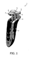
- FIG 1 shows a shaving appliance 1 according to the present invention
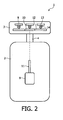
- Figure 4 provides a diagrammatic representation of the shaving appliance 1.
- a shaving appliance is a hand-held device which is suitable to be used for removing hairs from skin by performing an action commonly known as shaving, which is cutting through hairs at a position close to the skin.
- the shaving appliance 1 comprises a handle 2 for allowing a user to take hold of the shaving appliance 1, and a shaving unit 3, which is suitable to contact an area of skin having hairs to be shaved off.
- the shaving unit 3 is connected to the handle 2 through a central shaft member 4, wherein the connection of the shaving unit 3 to the handle 2 may be detachable.
- the shaving appliance 1 is shown in a typical orientation, namely an orientation in which a side of the shaving appliance 1 where the shaving unit 3 is present extends upwards.
- a typical orientation namely an orientation in which a side of the shaving appliance 1 where the shaving unit 3 is present extends upwards.
- the shaving appliance 1 is assumed that the shaving appliance 1 is in this orientation. In any case, that does not alter the fact that the shaving appliance 1 may be used in any suitable orientation.
- the shaving unit 3 comprises three shaving elements 5, which are arranged in a triangle formation.
- the number of shaving elements 5 may be chosen freely, and may therefore also be less than three or more than three.
- each of the shaving elements 5 may be arranged so as to be movable to a certain extent, so as to facilitate following a contour of an area of skin to be shaved.
- the shaving elements 5 may be pivotable, to a limited extent, with respect to the central shaft member 4.
- Each shaving element 5 comprises a cap 6, which is arranged at a top side of the shaving element 5, and which is held in a ring-shaped cap holder 7, and which has a plurality of holes for letting through hairs to be shaved off.
- a cutting member 8 is rotatably arranged.
- the cutting member 8, which is only diagrammatically shown in Figure 2 , may have a design known per se, according to which the cutting member 8 comprises a disc and cutters which are arranged along a circumference of the disc. During operation of the shaving appliance 1, the disc of the cutting member 8 is rotated, and hairs extending through the holes in the cap 6 are cut off when they are hit by a cutter of the cutting member 8.
- the shaving appliance 1 For the purpose of driving the cutting members 8, the shaving appliance 1 comprises a number of components, which are diagrammatically shown in Figure 2 , and which will be described in the following.
- the shaving appliance 1 comprises a motor 9, which is located in the handle 2.
- a gear wheel 10 In the shaving unit 3, at a central position, a gear wheel 10 is arranged, which will hereinafter be referred to as primary gear wheel 10.
- the primary gear wheel 10 is coupled in any suitable manner to an output shaft 11 of the motor 9, which is a primary drive shaft 11 to the gear wheel 10.
- the coupling of the primary gear wheel 10 to the primary drive shaft 11 is diagrammatically depicted by means of a dashed line.
- Each shaving element 5 accommodates a gear wheel 12, which is in engagement with the primary gear wheel 10.
- the gear wheels 12, which are located inside the shaving element 5, will be referred to as secondary gear wheels 12.
- a drive shaft 13 for driving the cutting member 8, which will hereinafter be referred to as secondary drive shaft 13, extends from each secondary gear wheel 12, and the cutting member 8 is coupled to the secondary drive shaft 13 through a suitable coupling member 14.
- the motor 9 When the shaving appliance 1 is operated, the motor 9 is in an activated condition, as a result of which the primary drive shaft 11 and the primary gear wheel 10 coupled to the primary drive shaft 11 are rotated about a central rotation axis. As the primary gear wheel 10 is in engagement with the secondary gear wheels 12, the rotation of the primary gear wheel 10 about the central rotation axis causes rotations of the secondary gear wheels 12 about their respective rotation axes. Consequently, due to the fact that each cutting member 8 is coupled to a secondary gear wheel 12 through a secondary drive shaft 13 and a coupling member 14, rotations of the cutting members 8 are realized. When a user of the shaving appliance 1 moves the shaving unit 3 across an area of skin, hairs extending through the holes in the caps 6 of the shaving elements 5 are cut off by the cutters of the cutting members 8.
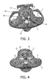
- FIG 3 a first embodiment of the shaving unit 3 is shown, wherein a number of components of the shaving unit 3, including the caps 6 and the cutting members 8, are omitted for the sake of clarity.
- Figure 3 shows that the cap holders 7 are hingably arranged in the shaving unit 3, wherein the cap holders 7 are movable between an opened position as shown in this Figure and a closed position as shown in Figure 1 .
- the cap holder 7 of a particular shaving element 5 is in the opened position, the cap 6 and the cutting member 8 of that shaving element 5 may be removed, which may be useful for cleaning purposes, for example.
- the shaving unit 3 is equipped with means 15 for generating electric energy at the location of the shaving unit 3. It is advantageous to have such means 15 at a location inside the shaving unit 3, as this allows having one or more electric components at the location of the shaving unit 3, without a need for an external electric connection, which might be a connection towards the handle 2.
- Examples of electric components which may be located in the shaving unit 3 are cleaning LEDs for emitting ultraviolet rays, components for retaining and releasing the cap holder 7, micro heating components, micro cooling components, a light source in order to visualize a rotating cutting member 8 in a stroboscopic manner, a light source in order to visualize a cleaning process of the shaving unit 3 which is performed by using cleaning fluid, components suitable to be used at locations where drying of difficult-to-reach areas needs to be performed, and integrated circuits (ICs) for wireless communication purposes from the shaving unit 3 to the handle 2 or a device for subjecting the unit 3 to a cleaning action.
- the means 15 for generating electric energy comprise a permanent magnet 16 which is mounted on the primary gear wheel 10.
- the magnet 16 can be insert molded in the primary gear wheel 10.
- the means 15 for generating electric energy comprise at least one electric coil 18. It is well-known that electric energy can be generated by subjecting a coil to an alternating magnetic field, on the basis of a physical process called induction. In the shaving unit 3, the alternating magnetic field is obtained by virtue of the rotatably arranged magnet 16 which is connected to the primary gear wheel 10.
- the permanent magnet 16 is surrounded by three other permanent magnets 17, wherein each of these magnets 17 extends through an electric coil 18.
- the coils 18 are subjected to an alternating magnetic field, as a result of which electric energy is generated.
- This electric energy may be used for operating one or more electric components through a connection of these components to the coils 18. It is noted that the way in which electric energy is generated in the first embodiment of the shaving unit 3 is comparable to the way in which an electric motor having a rotor surrounded by a number of stators is operated to generate electric energy.
- Figure 4 serves to illustrate another example, namely an example in which a single coil 18 is provided having an overall angular shape.
- the coil 18 is arranged right above the gear wheel 10 and the magnet 16, and its diameter is in the same order as the diameter of the magnet 16.
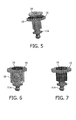
- Figure 5 shows an assembly of the primary gear wheel 10, the magnet 16, the coil 18, and a drive shaft end portion 11a on which the gear wheel 10 is mounted.
- FIG. 6 Yet another embodiment of the means 15 for generating electric energy during operation of the shaving appliance 1 is illustrated by Figures 6 and 7 .
- the permanent magnet 16 coupled to the primary gear wheel 10 is shaped like a disc.
- the magnet 16 is shaped like a cylinder, as is clearly shown in Figure 7 .
- the coil 18 which is part of this embodiment of the means 15 for generating electric energy is arranged such as to encompass the magnet 16. In other words, an arrangement is obtained in which the magnet 16 extends through the coil 18, as is clearly shown in Figure 6 .
- the means 15 for generating electric energy at the location of the shaving unit 3 other examples are feasible as well.
- An advantageous aspect of the present invention is that the generation of electric energy is based on the movement which is needed to drive the cutting members 8 of the shaving unit 3, so that an embodiment of the means 15 for generating electric energy may be compact and does not need additional drive components.
- a shaving appliance 1 which comprises a shaving unit 3 which has at least one movably arranged member 8 adapted to cut through hairs, and driving means 10, 11 a, 12, 13 adapted to impose a movement on the cutting member 8, and which further comprises means 15 for generating electric energy at the location of the shaving unit 3.
- the means 15 for generating electric energy are associated with the driving means 10, 11a, 12, 13, and are adapted to employ movement of at least one movable member of the driving means 10, 11 a, 12, 13 in a process of generating electric energy.
- the means 15 for generating electric energy comprise a permanent magnet 16 and an electric coil 18, wherein the magnet 16 may be mounted on a movably arranged component of the driving means 10, 11a, 12, 13.
Landscapes
- Life Sciences & Earth Sciences (AREA)
- Forests & Forestry (AREA)
- Engineering & Computer Science (AREA)
- Mechanical Engineering (AREA)
- Dry Shavers And Clippers (AREA)
- Magnetic Treatment Devices (AREA)
- Percussion Or Vibration Massage (AREA)
- Food-Manufacturing Devices (AREA)
Claims (11)
- Appareil ménager (1) qui est adapté de manière à effectuer un processus de rasage, c'est-à-dire un processus d'enlèvement de poils de la peau en coupant les poils dans une position qui se situe proche de la peau, comprenant une poignée (2) qui est destinée à être saisie par un utilisateur lors de l'application prévue de l'appareil (1) et comprenant une unité d'action fonctionnelle (3) qui est montée sur la poignée (2) pour effectuer une action qui est directement liée à une fonction prévue de l'appareil (1), dans lequel au moins un élément disposé de façon mobile (8, 10, 11a, 12, 13) qui est adapté de manière à couper des poils se situe dans l'unité d'action fonctionnelle (3) et dans lequel la poignée (2) enferme des moyens (9) pour fournir de la puissance à l'élément disposé de façon mobile (8, 10, 11a, 12, 13), caractérisé en ce que des moyens (15) sont prévus pour générer de l'énergie électrique à l'emplacement de l'unité d'action fonctionnelle (3), qui sont associés à l'élément disposé de façon mobile (8, 10, 11a, 12, 13) et qui sont adaptés de manière à utiliser le mouvement de l'élément disposé de façon mobile (8, 10, 11a, 12, 13) dans un processus de génération d'énergie électrique dans lequel au moins un composant électrique se situe dans l'unité d'action fonctionnelle (3) dans laquelle ledit composant électrique est adapté de manière à utiliser de l'énergie électrique qui est générée par lesdits moyens (15) pour son fonctionnement.
- Appareil ménager (1) selon la revendication 1, dans lequel au moins un élément disposé de façon mobile (8) pour effectuer l'action qui est directement liée à la fonction prévue de l'appareil (1) aussi bien que les moyens d'entraînement (10, 11a, 12, 13) qui sont adaptés de manière à imposer un mouvement à l'élément disposé de façon mobile (8) se situent dans l'unité d'action fonctionnelle (3) dans laquelle les moyens (15) pour générer de l'énergie électrique sont associés aux moyens d'entraînement (10, 11a, 12, 13) et sont adaptés de manière à utiliser le mouvement d'au moins un élément mobile des moyens d'entraînement (10, 11a, 12, 13) dans le processus de génération d'énergie électrique.
- Appareil ménager (1) selon la revendication 2, dans lequel les moyens d'entraînement (10, 11a, 12, 13) comprennent une roue dentée disposée de façon rotative (10) et dans lequel au moins un élément des moyens (15) pour générer de l'énergie électrique est fixé à la roue dentée (10).
- Appareil ménager (1) selon la revendication 3, dans lequel l'unité d'action fonctionnelle (3) comprend au moins deux éléments disposés de façon mobile (8) où la roue dentée (10) présente une position centrale entre les éléments disposés de façon mobile (8) et sert à entraîner tous les éléments disposés de façon mobile (8).
- Appareil ménager (1) selon la revendication 1, dans lequel les moyens (15) pour générer de l'énergie électrique comprennent un aimant permanent (16) et une bobine électrique (18).
- Appareil ménager (1) selon la revendication 1, comprenant en outre un arbre d'entraînement (11) qui fait saillie de la poignée (2) et qui s'étend dans l'unité d'action fonctionnelle (3).
- Unité d'action fonctionnelle (3) pour être utilisée dans un appareil ménager (1) selon la revendication 1, ladite unité d'action fonctionnelle étant adaptée de manière à effectuer une action qui est directement liée à une fonction prévue de l'appareil (1), et comprenant au moins un élément disposé de façon mobile (8, 10, 11a, 12, 13) qui est adapté de manière à couper des poils, caractérisé en ce que l'unité d'action fonctionnelle (3) comprend des moyens (15) pour générer de l'énergie électrique qui sont associés à l'élément disposé de façon mobile (8, 10, 11a, 12, 13) et qui sont adaptés de manière à utiliser le mouvement de l'élément disposé de façon mobile (8, 10, 11a, 12, 13) dans un processus de génération d'énergie électrique, et au moins un composant électrique qui est adapté de manière à utiliser de l'énergie électrique qui est générée par lesdits moyens (15) pour son fonctionnement.
- Unité d'action fonctionnelle (3) selon la revendication 7, comprenant au moins un élément disposé de façon mobile (8) pour effectuer l'action qui est directement liée à la fonction prévue de l'appareil (1) dans lequel l'unité d'action fonctionnelle (3) doit être utilisée et des moyens d'entraînement (10, 11a, 12, 13) qui sont adaptés de manière à imposer un mouvement à l'élément disposé de façon mobile (8) où les moyens (15) pour générer de l'énergie électrique sont associés aux moyens d'entraînement (10, 11a, 12, 13) et sont adaptés de manière à utiliser le mouvement d'au moins un élément mobile des moyens d'entraînement (10, 11a, 12, 13) dans le processus de génération d'énergie électrique.
- Unité d'action fonctionnelle (3) selon la revendication 8, dans laquelle les moyens d'entraînement (10, 11a, 12, 13) comprennent une roue dentée disposée de façon rotative (10) et dans lequel au moins un élément des moyens (15) pour générer de l'énergie électrique est fixé à la roue dentée (10).
- Unité d'action fonctionnelle (3) selon la revendication 9, comprenant au moins deux éléments disposés de façon mobile (8) où la roue dentée (10) présente une position centrale entre les éléments disposés de façon mobile (8) et sert à entraîner tous les éléments disposés de façon mobile (8).
- Unité d'action fonctionnelle (3) selon la revendication 7, dans laquelle les moyens (15) pour générer de l'énergie électrique comprennent un aimant permanent (16) et une bobine électrique (18).
Priority Applications (1)
| Application Number | Priority Date | Filing Date | Title |
|---|---|---|---|
| EP09757913A EP2296850B1 (fr) | 2008-05-27 | 2009-05-20 | Appareil domestique comprenant des moyens pour générer de l'énergie électrique dans une unité à action fonctionnelle |
Applications Claiming Priority (3)
| Application Number | Priority Date | Filing Date | Title |
|---|---|---|---|
| EP08156956 | 2008-05-27 | ||
| EP09757913A EP2296850B1 (fr) | 2008-05-27 | 2009-05-20 | Appareil domestique comprenant des moyens pour générer de l'énergie électrique dans une unité à action fonctionnelle |
| PCT/IB2009/052115 WO2009147561A2 (fr) | 2008-05-27 | 2009-05-20 | Appareil domestique comprenant des moyens pour générer de l'énergie électrique dans une unité à action fonctionnelle |
Publications (2)
| Publication Number | Publication Date |
|---|---|
| EP2296850A2 EP2296850A2 (fr) | 2011-03-23 |
| EP2296850B1 true EP2296850B1 (fr) | 2012-09-26 |
Family
ID=41398616
Family Applications (1)
| Application Number | Title | Priority Date | Filing Date |
|---|---|---|---|
| EP09757913A Active EP2296850B1 (fr) | 2008-05-27 | 2009-05-20 | Appareil domestique comprenant des moyens pour générer de l'énergie électrique dans une unité à action fonctionnelle |
Country Status (6)
| Country | Link |
|---|---|
| US (1) | US9126345B2 (fr) |
| EP (1) | EP2296850B1 (fr) |
| JP (1) | JP5632832B2 (fr) |
| CN (1) | CN102046339B (fr) |
| RU (1) | RU2508186C2 (fr) |
| WO (1) | WO2009147561A2 (fr) |
Families Citing this family (15)
| Publication number | Priority date | Publication date | Assignee | Title |
|---|---|---|---|---|
| JP5215301B2 (ja) * | 2006-07-14 | 2013-06-19 | コーニンクレッカ フィリップス エレクトロニクス エヌ ヴィ | 切除される毛を収集するための空間を有するシェーバ |
| US9009978B2 (en) | 2009-01-09 | 2015-04-21 | Koninklijke Philips N.V. | Shaver having spaces for collecting cut-off hairs |
| EP2822606A4 (fr) * | 2012-03-08 | 2015-12-23 | Daniel Moyal | Brosse de séchage à air chaud électroluminescente débranchable |
| BR112015008478B1 (pt) * | 2013-11-05 | 2020-11-03 | Koninklijke Philips N.V. | dispositivo de cuidados pessoais |
| WO2017121623A1 (fr) | 2016-01-12 | 2017-07-20 | Koninklijke Philips N.V. | Appareil domestique |
| CN105729507A (zh) * | 2016-04-25 | 2016-07-06 | 浙江美森电器有限公司 | 一种浮动刀头及剃须刀 |
| EP3354425B1 (fr) * | 2017-01-26 | 2020-07-29 | Braun GmbH | Rasoir ayant une source de lumière |
| US11186000B2 (en) * | 2017-01-27 | 2021-11-30 | Koninklijke Philips N.V. | Shaving unit and shaving apparatus with supporting structure for external cutting member |
| AU201715925S (en) * | 2017-03-31 | 2017-10-23 | Koninklijke Philips Nv | Shaver |
| AU201715869S (en) * | 2017-03-31 | 2017-10-19 | Koninklijke Philips Nv | Shaver |
| USD845545S1 (en) | 2018-08-21 | 2019-04-09 | E. Mishan & Sons, Inc. | Rotary shaver |
| EP3643461A1 (fr) * | 2018-10-23 | 2020-04-29 | Koninklijke Philips N.V. | Appareil portatif ayant une structure de couplage améliorée pour une fixation fonctionnelle de l'appareil |
| EP3835009A1 (fr) * | 2019-12-11 | 2021-06-16 | Koninklijke Philips N.V. | Unité de coupe de cheveux destiné à être utilisé dans un appareil de coupe de cheveux |
| USD945071S1 (en) * | 2021-03-16 | 2022-03-01 | Guangdong Huanengda Electrical Appliances Co., Ltd | Electric shaver |
| ES2978983T3 (es) * | 2021-07-27 | 2024-09-23 | Koninklijke Philips Nv | Unidad de afeitado y máquina de afeitar eléctrica que comprende la misma |
Family Cites Families (33)
| Publication number | Priority date | Publication date | Assignee | Title |
|---|---|---|---|---|
| US1538992A (en) * | 1920-12-20 | 1925-05-26 | Nat Carbon Co Inc | Flash light and recharging device for the battery thereof |
| US2222308A (en) * | 1936-07-11 | 1940-11-19 | Company The Stamford Trust | Safety razor |
| US2301147A (en) * | 1937-03-18 | 1942-11-03 | Schaaf Alexander | Electric safety razor |
| US2279682A (en) * | 1938-03-31 | 1942-04-14 | Jackson Jesse Atwater | Shearing shaver |
| US2383421A (en) * | 1944-08-07 | 1945-08-21 | Maxwell I Schultz | Ultraviolet ray applicator |
| SU76080A1 (ru) * | 1948-08-07 | 1948-11-30 | В.А. Щепетков | Машинка дл стрижки волос |
| DE1048189B (de) * | 1956-08-06 | 1958-12-31 | Otto Huebner | Elektrischer Rasierapparat |
| US3257599A (en) * | 1960-01-11 | 1966-06-21 | Sperry Rand Corp | Battery operated electric shaver and charger |
| US3141239A (en) * | 1960-03-08 | 1964-07-21 | Philips Corp | Dry shaving apparatus comprising a shaving head with a cooling system |
| US3298101A (en) * | 1964-03-30 | 1967-01-17 | Richard W Maccarthy | Counter-rotating head electric razor |
| US3675324A (en) * | 1969-05-07 | 1972-07-11 | Matsushita Electric Works Ltd | Electric dry shaver |
| US3756105A (en) * | 1971-10-28 | 1973-09-04 | Ultrasonic Systems | Ultrasonic electric shaver |
| JPS5331056B2 (fr) * | 1972-02-01 | 1978-08-31 | ||
| JPS5363154A (en) * | 1976-11-15 | 1978-06-06 | Matsushita Electric Works Ltd | Electric shaver incorporating hand-operated generator |
| JPS59107551U (ja) * | 1983-01-07 | 1984-07-19 | 九州日立マクセル株式会社 | 小型電気機器 |
| RU1773717C (ru) * | 1990-05-23 | 1992-11-07 | Р.М.Гасанлы | "Устройство дл удалени волос ного покрова на труднодоступных участках "Сабина" |
| CN2134266Y (zh) * | 1991-12-21 | 1993-05-26 | 鬲仲远 | 多功能手动电筒剃须刀 |
| US6226870B1 (en) * | 1998-09-08 | 2001-05-08 | Benjamin J. Barish | Electrical shaver and auxiliary device particularly useful therewith |
| DE19859622A1 (de) * | 1998-12-23 | 2000-07-06 | Braun Gmbh | Antriebseinrichtung für oszillierende elektrische Produkte des persönlichen Bedarfs, insbesondere Trockenrasierer |
| DE10052296C1 (de) | 2000-10-20 | 2002-04-04 | Braun Gmbh | Elektrisch betriebenes Haarentfernungsgerät mit einer Beleuchtungseinrichtung |
| JP2002166374A (ja) * | 2000-12-04 | 2002-06-11 | Nissan Motor Co Ltd | 回転工具用照明装置 |
| US6862534B2 (en) * | 2001-12-14 | 2005-03-01 | Optiscan Biomedical Corporation | Method of determining an analyte concentration in a sample from an absorption spectrum |
| DE10242092A1 (de) * | 2002-09-11 | 2004-04-01 | Braun Gmbh | Eletrisches Kleingerät mit einer Antriebseinrichtung zur Erzeugung einer oszillierenden Bewegung |
| US7504751B2 (en) * | 2002-09-11 | 2009-03-17 | Braun Gmbh | Small electric appliance with a drive mechanism for generating an oscillatory motion |
| US20040194316A1 (en) | 2003-04-04 | 2004-10-07 | Ray-Ming Lin | Shaver having germ-killing device |
| DE10330978A1 (de) * | 2003-07-09 | 2005-02-10 | Braun Gmbh | Elektrisches Kleingerät mit einem Elektromotor zur Erzeugung einer oszillierenden Bewegung |
| ATE500932T1 (de) | 2004-12-22 | 2011-03-15 | Koninkl Philips Electronics Nv | Rotationsrasierer mit verbessertem antrieb und stützstruktur für den rasierkopf |
| AU2006247036C1 (en) | 2005-05-18 | 2010-08-26 | Biolase, Inc. | Electromagnetic radiation emitting toothbrush and dentifrice system |
| US7232238B2 (en) * | 2005-08-08 | 2007-06-19 | Rsga International, Inc. | Renewable energy flashlight |
| DE102005044175A1 (de) * | 2005-09-16 | 2007-03-29 | Braun Gmbh | Haarentfernungsgerät |
| DE102005060537A1 (de) * | 2005-12-17 | 2007-06-21 | Braun Gmbh | Elektrischer Rasierapparat mit oszillierendem Scherkopf |
| US20070177377A1 (en) * | 2006-02-02 | 2007-08-02 | Xiang Yang Ding | Rechargeable flashlight |
| DE102008032150A1 (de) * | 2008-07-08 | 2010-01-14 | Braun Gmbh | Elektrischer Rasierer mit integrierter Kühlung |
-
2009
- 2009-05-20 JP JP2011511130A patent/JP5632832B2/ja active Active
- 2009-05-20 EP EP09757913A patent/EP2296850B1/fr active Active
- 2009-05-20 US US12/993,123 patent/US9126345B2/en active Active
- 2009-05-20 WO PCT/IB2009/052115 patent/WO2009147561A2/fr not_active Ceased
- 2009-05-20 RU RU2010153340/02A patent/RU2508186C2/ru active
- 2009-05-20 CN CN200980119509.5A patent/CN102046339B/zh active Active
Also Published As
| Publication number | Publication date |
|---|---|
| CN102046339B (zh) | 2014-04-16 |
| EP2296850A2 (fr) | 2011-03-23 |
| JP5632832B2 (ja) | 2014-11-26 |
| JP2011521696A (ja) | 2011-07-28 |
| CN102046339A (zh) | 2011-05-04 |
| RU2508186C2 (ru) | 2014-02-27 |
| US20110067243A1 (en) | 2011-03-24 |
| WO2009147561A2 (fr) | 2009-12-10 |
| US9126345B2 (en) | 2015-09-08 |
| WO2009147561A3 (fr) | 2010-07-15 |
| RU2010153340A (ru) | 2012-07-10 |
Similar Documents
| Publication | Publication Date | Title |
|---|---|---|
| US9126345B2 (en) | Domestic appliance comprising means for generating electric energy in a functional action unit | |
| JP6402859B2 (ja) | 美容装置 | |
| JP5356025B2 (ja) | 除毛装置 | |
| JP5043846B2 (ja) | 除毛装置 | |
| JP2010536462A (ja) | 手持ち式パーソナルケア装置 | |
| RU2745523C2 (ru) | Бытовое устройство | |
| EP2213427B1 (fr) | Ensemble de lame pour rasoir électrique | |
| JP6882489B2 (ja) | 光源を有するかみそり | |
| CN103812299A (zh) | 执行器及电动理容美容器具 | |
| TW200927405A (en) | Hair trimmer | |
| US7717867B2 (en) | Massage apparatus with positional set-up actuator | |
| JP2011135840A (ja) | 電動刈込機 | |
| CN104508959A (zh) | 电动作业机 | |
| CN216455435U (zh) | 电动牙刷 | |
| CN112008770B (zh) | 一种能整体浮动的电动剃须刀 | |
| CN210389266U (zh) | 一种能整体浮动的电动剃须刀 | |
| CN104985614B (zh) | 位移理发剪 | |
| EP4617017A3 (fr) | Appareil de toilettage électrique comprenant un système de couplage magnétique | |
| CN212853613U (zh) | 一种消除眼袋的医疗器械 | |
| JP2024541332A (ja) | シェービングユニットの外部切断部材の回転 | |
| CN103846499B (zh) | 往复锯 | |
| CN221391155U (zh) | 一种三刀头剃须刀驱动电机 | |
| JP4355401B2 (ja) | セパレート式電気カミソリ | |
| CN217883046U (zh) | 一种电机、手持式电动工具 | |
| BR112020013156A2 (pt) | dispositivo conectável a um aparelho com um elemento de acionamento rotacional e kit de peças |
Legal Events
| Date | Code | Title | Description |
|---|---|---|---|
| PUAI | Public reference made under article 153(3) epc to a published international application that has entered the european phase |
Free format text: ORIGINAL CODE: 0009012 |
|
| 17P | Request for examination filed |
Effective date: 20110117 |
|
| AK | Designated contracting states |
Kind code of ref document: A2 Designated state(s): AT BE BG CH CY CZ DE DK EE ES FI FR GB GR HR HU IE IS IT LI LT LU LV MC MK MT NL NO PL PT RO SE SI SK TR |
|
| DAX | Request for extension of the european patent (deleted) | ||
| GRAP | Despatch of communication of intention to grant a patent |
Free format text: ORIGINAL CODE: EPIDOSNIGR1 |
|
| GRAS | Grant fee paid |
Free format text: ORIGINAL CODE: EPIDOSNIGR3 |
|
| GRAA | (expected) grant |
Free format text: ORIGINAL CODE: 0009210 |
|
| AK | Designated contracting states |
Kind code of ref document: B1 Designated state(s): AT BE BG CH CY CZ DE DK EE ES FI FR GB GR HR HU IE IS IT LI LT LU LV MC MK MT NL NO PL PT RO SE SI SK TR |
|
| REG | Reference to a national code |
Ref country code: GB Ref legal event code: FG4D |
|
| REG | Reference to a national code |
Ref country code: CH Ref legal event code: EP |
|
| REG | Reference to a national code |
Ref country code: AT Ref legal event code: REF Ref document number: 576804 Country of ref document: AT Kind code of ref document: T Effective date: 20121015 |
|
| REG | Reference to a national code |
Ref country code: IE Ref legal event code: FG4D |
|
| REG | Reference to a national code |
Ref country code: DE Ref legal event code: R096 Ref document number: 602009010052 Country of ref document: DE Effective date: 20121115 |
|
| PG25 | Lapsed in a contracting state [announced via postgrant information from national office to epo] |
Ref country code: LT Free format text: LAPSE BECAUSE OF FAILURE TO SUBMIT A TRANSLATION OF THE DESCRIPTION OR TO PAY THE FEE WITHIN THE PRESCRIBED TIME-LIMIT Effective date: 20120926 Ref country code: FI Free format text: LAPSE BECAUSE OF FAILURE TO SUBMIT A TRANSLATION OF THE DESCRIPTION OR TO PAY THE FEE WITHIN THE PRESCRIBED TIME-LIMIT Effective date: 20120926 Ref country code: HR Free format text: LAPSE BECAUSE OF FAILURE TO SUBMIT A TRANSLATION OF THE DESCRIPTION OR TO PAY THE FEE WITHIN THE PRESCRIBED TIME-LIMIT Effective date: 20120926 Ref country code: NO Free format text: LAPSE BECAUSE OF FAILURE TO SUBMIT A TRANSLATION OF THE DESCRIPTION OR TO PAY THE FEE WITHIN THE PRESCRIBED TIME-LIMIT Effective date: 20121226 |
|
| REG | Reference to a national code |
Ref country code: AT Ref legal event code: MK05 Ref document number: 576804 Country of ref document: AT Kind code of ref document: T Effective date: 20120926 |
|
| REG | Reference to a national code |
Ref country code: LT Ref legal event code: MG4D Effective date: 20120926 |
|
| REG | Reference to a national code |
Ref country code: NL Ref legal event code: VDEP Effective date: 20120926 |
|
| PG25 | Lapsed in a contracting state [announced via postgrant information from national office to epo] |
Ref country code: GR Free format text: LAPSE BECAUSE OF FAILURE TO SUBMIT A TRANSLATION OF THE DESCRIPTION OR TO PAY THE FEE WITHIN THE PRESCRIBED TIME-LIMIT Effective date: 20121227 Ref country code: SE Free format text: LAPSE BECAUSE OF FAILURE TO SUBMIT A TRANSLATION OF THE DESCRIPTION OR TO PAY THE FEE WITHIN THE PRESCRIBED TIME-LIMIT Effective date: 20120926 Ref country code: SI Free format text: LAPSE BECAUSE OF FAILURE TO SUBMIT A TRANSLATION OF THE DESCRIPTION OR TO PAY THE FEE WITHIN THE PRESCRIBED TIME-LIMIT Effective date: 20120926 Ref country code: LV Free format text: LAPSE BECAUSE OF FAILURE TO SUBMIT A TRANSLATION OF THE DESCRIPTION OR TO PAY THE FEE WITHIN THE PRESCRIBED TIME-LIMIT Effective date: 20120926 |
|
| PG25 | Lapsed in a contracting state [announced via postgrant information from national office to epo] |
Ref country code: BE Free format text: LAPSE BECAUSE OF FAILURE TO SUBMIT A TRANSLATION OF THE DESCRIPTION OR TO PAY THE FEE WITHIN THE PRESCRIBED TIME-LIMIT Effective date: 20120926 Ref country code: RO Free format text: LAPSE BECAUSE OF FAILURE TO SUBMIT A TRANSLATION OF THE DESCRIPTION OR TO PAY THE FEE WITHIN THE PRESCRIBED TIME-LIMIT Effective date: 20120926 Ref country code: CZ Free format text: LAPSE BECAUSE OF FAILURE TO SUBMIT A TRANSLATION OF THE DESCRIPTION OR TO PAY THE FEE WITHIN THE PRESCRIBED TIME-LIMIT Effective date: 20120926 Ref country code: IS Free format text: LAPSE BECAUSE OF FAILURE TO SUBMIT A TRANSLATION OF THE DESCRIPTION OR TO PAY THE FEE WITHIN THE PRESCRIBED TIME-LIMIT Effective date: 20130126 Ref country code: ES Free format text: LAPSE BECAUSE OF FAILURE TO SUBMIT A TRANSLATION OF THE DESCRIPTION OR TO PAY THE FEE WITHIN THE PRESCRIBED TIME-LIMIT Effective date: 20130106 Ref country code: NL Free format text: LAPSE BECAUSE OF FAILURE TO SUBMIT A TRANSLATION OF THE DESCRIPTION OR TO PAY THE FEE WITHIN THE PRESCRIBED TIME-LIMIT Effective date: 20120926 Ref country code: EE Free format text: LAPSE BECAUSE OF FAILURE TO SUBMIT A TRANSLATION OF THE DESCRIPTION OR TO PAY THE FEE WITHIN THE PRESCRIBED TIME-LIMIT Effective date: 20120926 |
|
| PG25 | Lapsed in a contracting state [announced via postgrant information from national office to epo] |
Ref country code: PL Free format text: LAPSE BECAUSE OF FAILURE TO SUBMIT A TRANSLATION OF THE DESCRIPTION OR TO PAY THE FEE WITHIN THE PRESCRIBED TIME-LIMIT Effective date: 20120926 Ref country code: SK Free format text: LAPSE BECAUSE OF FAILURE TO SUBMIT A TRANSLATION OF THE DESCRIPTION OR TO PAY THE FEE WITHIN THE PRESCRIBED TIME-LIMIT Effective date: 20120926 Ref country code: PT Free format text: LAPSE BECAUSE OF FAILURE TO SUBMIT A TRANSLATION OF THE DESCRIPTION OR TO PAY THE FEE WITHIN THE PRESCRIBED TIME-LIMIT Effective date: 20130128 |
|
| PG25 | Lapsed in a contracting state [announced via postgrant information from national office to epo] |
Ref country code: AT Free format text: LAPSE BECAUSE OF FAILURE TO SUBMIT A TRANSLATION OF THE DESCRIPTION OR TO PAY THE FEE WITHIN THE PRESCRIBED TIME-LIMIT Effective date: 20120926 |
|
| PG25 | Lapsed in a contracting state [announced via postgrant information from national office to epo] |
Ref country code: DK Free format text: LAPSE BECAUSE OF FAILURE TO SUBMIT A TRANSLATION OF THE DESCRIPTION OR TO PAY THE FEE WITHIN THE PRESCRIBED TIME-LIMIT Effective date: 20120926 Ref country code: BG Free format text: LAPSE BECAUSE OF FAILURE TO SUBMIT A TRANSLATION OF THE DESCRIPTION OR TO PAY THE FEE WITHIN THE PRESCRIBED TIME-LIMIT Effective date: 20121226 |
|
| PLBE | No opposition filed within time limit |
Free format text: ORIGINAL CODE: 0009261 |
|
| STAA | Information on the status of an ep patent application or granted ep patent |
Free format text: STATUS: NO OPPOSITION FILED WITHIN TIME LIMIT |
|
| PG25 | Lapsed in a contracting state [announced via postgrant information from national office to epo] |
Ref country code: IT Free format text: LAPSE BECAUSE OF FAILURE TO SUBMIT A TRANSLATION OF THE DESCRIPTION OR TO PAY THE FEE WITHIN THE PRESCRIBED TIME-LIMIT Effective date: 20120926 |
|
| 26N | No opposition filed |
Effective date: 20130627 |
|
| REG | Reference to a national code |
Ref country code: DE Ref legal event code: R097 Ref document number: 602009010052 Country of ref document: DE Effective date: 20130627 |
|
| PG25 | Lapsed in a contracting state [announced via postgrant information from national office to epo] |
Ref country code: CY Free format text: LAPSE BECAUSE OF FAILURE TO SUBMIT A TRANSLATION OF THE DESCRIPTION OR TO PAY THE FEE WITHIN THE PRESCRIBED TIME-LIMIT Effective date: 20120926 |
|
| PG25 | Lapsed in a contracting state [announced via postgrant information from national office to epo] |
Ref country code: MC Free format text: LAPSE BECAUSE OF FAILURE TO SUBMIT A TRANSLATION OF THE DESCRIPTION OR TO PAY THE FEE WITHIN THE PRESCRIBED TIME-LIMIT Effective date: 20120926 |
|
| REG | Reference to a national code |
Ref country code: CH Ref legal event code: PL |
|
| PG25 | Lapsed in a contracting state [announced via postgrant information from national office to epo] |
Ref country code: LI Free format text: LAPSE BECAUSE OF NON-PAYMENT OF DUE FEES Effective date: 20130531 Ref country code: CH Free format text: LAPSE BECAUSE OF NON-PAYMENT OF DUE FEES Effective date: 20130531 |
|
| REG | Reference to a national code |
Ref country code: IE Ref legal event code: MM4A |
|
| PG25 | Lapsed in a contracting state [announced via postgrant information from national office to epo] |
Ref country code: IE Free format text: LAPSE BECAUSE OF NON-PAYMENT OF DUE FEES Effective date: 20130520 |
|
| REG | Reference to a national code |
Ref country code: DE Ref legal event code: R081 Ref document number: 602009010052 Country of ref document: DE Owner name: KONINKLIJKE PHILIPS N.V., NL Free format text: FORMER OWNER: KONINKLIJKE PHILIPS ELECTRONICS N.V., EINDHOVEN, NL Effective date: 20140328 |
|
| REG | Reference to a national code |
Ref country code: FR Ref legal event code: CD Owner name: KONINKLIJKE PHILIPS ELECTRONICS N.V., NL Effective date: 20141126 Ref country code: FR Ref legal event code: CA Effective date: 20141126 |
|
| PG25 | Lapsed in a contracting state [announced via postgrant information from national office to epo] |
Ref country code: MT Free format text: LAPSE BECAUSE OF FAILURE TO SUBMIT A TRANSLATION OF THE DESCRIPTION OR TO PAY THE FEE WITHIN THE PRESCRIBED TIME-LIMIT Effective date: 20120926 |
|
| PG25 | Lapsed in a contracting state [announced via postgrant information from national office to epo] |
Ref country code: MK Free format text: LAPSE BECAUSE OF FAILURE TO SUBMIT A TRANSLATION OF THE DESCRIPTION OR TO PAY THE FEE WITHIN THE PRESCRIBED TIME-LIMIT Effective date: 20120926 Ref country code: HU Free format text: LAPSE BECAUSE OF FAILURE TO SUBMIT A TRANSLATION OF THE DESCRIPTION OR TO PAY THE FEE WITHIN THE PRESCRIBED TIME-LIMIT; INVALID AB INITIO Effective date: 20090520 Ref country code: LU Free format text: LAPSE BECAUSE OF NON-PAYMENT OF DUE FEES Effective date: 20130520 |
|
| REG | Reference to a national code |
Ref country code: FR Ref legal event code: PLFP Year of fee payment: 8 |
|
| REG | Reference to a national code |
Ref country code: FR Ref legal event code: PLFP Year of fee payment: 9 |
|
| REG | Reference to a national code |
Ref country code: FR Ref legal event code: PLFP Year of fee payment: 10 |
|
| PGFP | Annual fee paid to national office [announced via postgrant information from national office to epo] |
Ref country code: TR Payment date: 20210507 Year of fee payment: 13 |
|
| PG25 | Lapsed in a contracting state [announced via postgrant information from national office to epo] |
Ref country code: TR Free format text: LAPSE BECAUSE OF NON-PAYMENT OF DUE FEES Effective date: 20220520 |
|
| PGFP | Annual fee paid to national office [announced via postgrant information from national office to epo] |
Ref country code: DE Payment date: 20250528 Year of fee payment: 17 |
|
| PGFP | Annual fee paid to national office [announced via postgrant information from national office to epo] |
Ref country code: GB Payment date: 20250520 Year of fee payment: 17 |
|
| PGFP | Annual fee paid to national office [announced via postgrant information from national office to epo] |
Ref country code: FR Payment date: 20250526 Year of fee payment: 17 |