EP2296871B1 - Conduite avec gaine a permeabilite reduite aux composes acides - Google Patents
Conduite avec gaine a permeabilite reduite aux composes acides Download PDFInfo
- Publication number
- EP2296871B1 EP2296871B1 EP09766013A EP09766013A EP2296871B1 EP 2296871 B1 EP2296871 B1 EP 2296871B1 EP 09766013 A EP09766013 A EP 09766013A EP 09766013 A EP09766013 A EP 09766013A EP 2296871 B1 EP2296871 B1 EP 2296871B1
- Authority
- EP
- European Patent Office
- Prior art keywords
- sheath
- pipe
- alkaline
- metal
- carbonates
- Prior art date
- Legal status (The legal status is an assumption and is not a legal conclusion. Google has not performed a legal analysis and makes no representation as to the accuracy of the status listed.)
- Active
Links
Images
Classifications
-
- B—PERFORMING OPERATIONS; TRANSPORTING
- B32—LAYERED PRODUCTS
- B32B—LAYERED PRODUCTS, i.e. PRODUCTS BUILT-UP OF STRATA OF FLAT OR NON-FLAT, e.g. CELLULAR OR HONEYCOMB, FORM
- B32B1/00—Layered products having a non-planar shape
- B32B1/08—Tubular products
-
- B—PERFORMING OPERATIONS; TRANSPORTING
- B32—LAYERED PRODUCTS
- B32B—LAYERED PRODUCTS, i.e. PRODUCTS BUILT-UP OF STRATA OF FLAT OR NON-FLAT, e.g. CELLULAR OR HONEYCOMB, FORM
- B32B15/00—Layered products comprising a layer of metal
- B32B15/04—Layered products comprising a layer of metal comprising metal as the main or only constituent of a layer, which is next to another layer of the same or of a different material
- B32B15/08—Layered products comprising a layer of metal comprising metal as the main or only constituent of a layer, which is next to another layer of the same or of a different material of synthetic resin
-
- B—PERFORMING OPERATIONS; TRANSPORTING
- B32—LAYERED PRODUCTS
- B32B—LAYERED PRODUCTS, i.e. PRODUCTS BUILT-UP OF STRATA OF FLAT OR NON-FLAT, e.g. CELLULAR OR HONEYCOMB, FORM
- B32B27/00—Layered products comprising a layer of synthetic resin
- B32B27/06—Layered products comprising a layer of synthetic resin as the main or only constituent of a layer, which is next to another layer of the same or of a different material
- B32B27/08—Layered products comprising a layer of synthetic resin as the main or only constituent of a layer, which is next to another layer of the same or of a different material of synthetic resin
-
- B—PERFORMING OPERATIONS; TRANSPORTING
- B32—LAYERED PRODUCTS
- B32B—LAYERED PRODUCTS, i.e. PRODUCTS BUILT-UP OF STRATA OF FLAT OR NON-FLAT, e.g. CELLULAR OR HONEYCOMB, FORM
- B32B27/00—Layered products comprising a layer of synthetic resin
- B32B27/18—Layered products comprising a layer of synthetic resin characterised by the use of special additives
- B32B27/20—Layered products comprising a layer of synthetic resin characterised by the use of special additives using fillers, pigments, thixotroping agents
-
- F—MECHANICAL ENGINEERING; LIGHTING; HEATING; WEAPONS; BLASTING
- F16—ENGINEERING ELEMENTS AND UNITS; GENERAL MEASURES FOR PRODUCING AND MAINTAINING EFFECTIVE FUNCTIONING OF MACHINES OR INSTALLATIONS; THERMAL INSULATION IN GENERAL
- F16L—PIPES; JOINTS OR FITTINGS FOR PIPES; SUPPORTS FOR PIPES, CABLES OR PROTECTIVE TUBING; MEANS FOR THERMAL INSULATION IN GENERAL
- F16L11/00—Hoses, i.e. flexible pipes
- F16L11/04—Hoses, i.e. flexible pipes made of rubber or flexible plastics
- F16L11/08—Hoses, i.e. flexible pipes made of rubber or flexible plastics with reinforcements embedded in the wall
- F16L11/081—Hoses, i.e. flexible pipes made of rubber or flexible plastics with reinforcements embedded in the wall comprising one or more layers of a helically wound cord or wire
-
- F—MECHANICAL ENGINEERING; LIGHTING; HEATING; WEAPONS; BLASTING
- F16—ENGINEERING ELEMENTS AND UNITS; GENERAL MEASURES FOR PRODUCING AND MAINTAINING EFFECTIVE FUNCTIONING OF MACHINES OR INSTALLATIONS; THERMAL INSULATION IN GENERAL
- F16L—PIPES; JOINTS OR FITTINGS FOR PIPES; SUPPORTS FOR PIPES, CABLES OR PROTECTIVE TUBING; MEANS FOR THERMAL INSULATION IN GENERAL
- F16L11/00—Hoses, i.e. flexible pipes
- F16L11/04—Hoses, i.e. flexible pipes made of rubber or flexible plastics
- F16L11/12—Hoses, i.e. flexible pipes made of rubber or flexible plastics with arrangements for particular purposes, e.g. specially profiled, with protecting layer, heated, electrically conducting
-
- B—PERFORMING OPERATIONS; TRANSPORTING
- B32—LAYERED PRODUCTS
- B32B—LAYERED PRODUCTS, i.e. PRODUCTS BUILT-UP OF STRATA OF FLAT OR NON-FLAT, e.g. CELLULAR OR HONEYCOMB, FORM
- B32B2255/00—Coating on the layer surface
-
- B—PERFORMING OPERATIONS; TRANSPORTING
- B32—LAYERED PRODUCTS
- B32B—LAYERED PRODUCTS, i.e. PRODUCTS BUILT-UP OF STRATA OF FLAT OR NON-FLAT, e.g. CELLULAR OR HONEYCOMB, FORM
- B32B2264/00—Composition or properties of particles which form a particulate layer or are present as additives
- B32B2264/10—Inorganic particles
- B32B2264/104—Oxysalt, e.g. carbonate, sulfate, phosphate or nitrate particles
-
- B—PERFORMING OPERATIONS; TRANSPORTING
- B32—LAYERED PRODUCTS
- B32B—LAYERED PRODUCTS, i.e. PRODUCTS BUILT-UP OF STRATA OF FLAT OR NON-FLAT, e.g. CELLULAR OR HONEYCOMB, FORM
- B32B2264/00—Composition or properties of particles which form a particulate layer or are present as additives
- B32B2264/10—Inorganic particles
- B32B2264/107—Ceramic
- B32B2264/108—Carbon, e.g. graphite particles
-
- B—PERFORMING OPERATIONS; TRANSPORTING
- B32—LAYERED PRODUCTS
- B32B—LAYERED PRODUCTS, i.e. PRODUCTS BUILT-UP OF STRATA OF FLAT OR NON-FLAT, e.g. CELLULAR OR HONEYCOMB, FORM
- B32B2307/00—Properties of the layers or laminate
- B32B2307/50—Properties of the layers or laminate having particular mechanical properties
-
- B—PERFORMING OPERATIONS; TRANSPORTING
- B32—LAYERED PRODUCTS
- B32B—LAYERED PRODUCTS, i.e. PRODUCTS BUILT-UP OF STRATA OF FLAT OR NON-FLAT, e.g. CELLULAR OR HONEYCOMB, FORM
- B32B2307/00—Properties of the layers or laminate
- B32B2307/70—Other properties
- B32B2307/714—Inert, i.e. inert to chemical degradation, corrosion
-
- B—PERFORMING OPERATIONS; TRANSPORTING
- B32—LAYERED PRODUCTS
- B32B—LAYERED PRODUCTS, i.e. PRODUCTS BUILT-UP OF STRATA OF FLAT OR NON-FLAT, e.g. CELLULAR OR HONEYCOMB, FORM
- B32B2597/00—Tubular articles, e.g. hoses, pipes
Definitions
- the present invention relates to the field of pipes for the transport of petroleum fluid comprising acidic compounds such as hydrogen sulphide and carbon dioxide.
- the invention is particularly applicable to hydrocarbons transported in pipes that may be under high pressures, greater than 100 bar and at high temperatures, greater than 70 ° C. or even 100 ° C., for long periods of time. that is to say, several years.
- the pipes are particularly used for offshore oil exploitation.
- the pipes may be metal tubes internally coated with a tube of polymeric material.
- the pipes may also be flexible pipes consisting of a superposition of sheaths of polymeric material and several layers of metal son helically wound.
- the document EP 844 429 proposes to introduce, in the sheath of polymer material, chemically active products with the acidic compounds (H 2 S and / or CO 2 ) so as to irreversibly neutralize the corrosive effects of said acid compounds and in order to avoid corrosive effects on the metal parts of the pipe.
- the acidic compounds H 2 S and / or CO 2
- the present invention proposes to improve the teaching of the document EP 844 429 proposing solutions to substantially increase the neutralizing effect of chemically active products with acidic compounds.
- the present invention relates to a pipe for transporting a petroleum effluent comprising at least one of the acidic compounds CO 2 and H 2 S.
- the pipe comprises at least one metal element and a tubular sheath of polymer material, the element metal being disposed outside the sheath.
- the sheath comprises a mixture of a polymeric material with a determined amount of chemically active products with said acid compounds so as to irreversibly neutralize the corrosive effects of said compounds and limit the corrosive effects on said metal elements.
- the conduct is characterized in that the chemically active products are introduced into the sheath in the form of particles with a specific surface area greater than 5 m 2 / g .
- the chemically active products can be introduced into the sheath in the form of particles having a particle size greater than 0.02 ⁇ m.
- the chemically active products may be chosen from metal oxides chosen from the group consisting of Fe 2 O 3 , PbO, ZnO, NiO, CoO, CdO, CuO, SnO 2 , MoO 3 , Fe 3 O 4 , Ag 2 O, CrO 2 , CrO 3 , Cr 2 O 3 , TiO, TiO 2 and Ti 2 O 3 are the alkali and alkaline earth oxides selected from CaO, Ca (OH) 2 and MgO.
- the chemically active products may also be selected from metal carbonates, metal chlorides, hydrated forms of metal carbonates and metal chlorides, hydroxylated forms of metal carbonates and metal chlorides, alkaline carbonates, alkaline earth carbonates, Alkaline chlorides, alkaline earth chlorides, hydrated forms of alkaline carbonates, alkaline earth carbonates, alkaline chlorides, alkaline earth chlorides and hydroxylated forms of alkaline carbonates, alkaline earth carbonates, alkaline chlorides, alkaline earth chlorides.
- the sheath may further comprise lamellar shaped fillers having a shape factor greater than 20, the mass concentration of said lamellar fillers in the sheath being at most equal to 10%.
- the sheath may further comprise adsorbent fillers which trap the acidic compounds, the adsorbent fillers being chosen from active carbons, zeolites and aluminas.
- the sheath may comprise additives for improving the mechanical properties of the sheath, the additives being chosen from poly (ethylene-octene), poly (ethylene-propylene), poly (ethylene-butene) and poly (styrene / ethylene). butylene / styrene).
- Chemically active products can be surface-chemically treated with silanes.
- the sheath may comprise polyolefins grafted maleic anhydride.
- the sheath may comprise at least two layers, a first layer comprising a first polymer material and a second layer comprising a second polymer material containing said determined quantity of chemically active products.
- the first layer may further comprise lamellar shaped charges having a shape factor greater than 20, the mass concentration of said lamellar fillers in the first layer being equal to a maximum of 10%.
- a coating may be deposited between the two layers, said coating containing an amount of said chemically active products.
- said determined amount of chemically active products may be distributed throughout the thickness of said sheath.
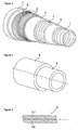
- the flexible pipe represented by the figure 1 consists of several layers described below from the inside to the outside of the pipe.
- the carcass 1 consists of a metal strip wound in a short pitch helix. It is intended for crush resistance under the effect of the external pressure applied to the pipe.
- the metal strip can be made from a deformed sheet or wire, each turn being stapled to the adjacent turns.
- Sealing sheaths 2 and 4 are made by extrusion of a polymer material, generally selected from polyolefins, polyamides and fluoropolymers.
- the arch 3 made of stapled or interlocking metal son ensures the resistance to the internal pressure in the pipe.
- the tensile armor plies 5 consist of metal wires wound helically at angles between 20 ° and 55 °. The plies are held by the ribbon 6.
- the polymer sheath 7 forms an external protection of the pipe.
- At least one of the sheaths 2 or 4 comprise chemically active charges with H 2 S and / or CO 2 .
- the driving represented by the figure 1 is of the "rough bore” type, that is to say that the fluid circulating in the pipe is in contact with the carcass 1.
- the pipe may be of the "smooth bore" type.
- the conduct represented by the figure 1 does not have a carcass 1.
- the polymer sheath 2 is directly in contact with the fluid circulating in the pipe.
- the conduct schematized by the figure 2 consists of a metal tube 8 whose inner surface is coated with a continuous sealing sheath 9 of polymeric material.
- sheath 9 comprises chemically active charges with H 2 S and / or CO 2 .
- the sealing sheaths are made from a mixture of polymer material and charges of agents that neutralize acidic compounds, such as H 2 S and CO 2 .
- the mixture is prepared at a temperature above the melting point of the polymeric material during extrusion operations of the sheath.
- the charges of neutralizing agents can be distributed throughout the thickness of the polymer material sealing sheath.
- the polymer material is preferably chosen from cross-linked or non-crosslinked polyolefins, for example polyethylene (PE) or polypropylene (PP).
- polyamides for example polyamide 11 (PA-11) or polyamide 12 (PA-12), fluorinated polymers, for example polyvinylidene fluoride (PVDF), polysulfides, for example phenylene polysulfide (PPS), ), polyurethanes (PU), polyesters, polyacetals, polyethers, for example polyethersulfone (PES), polyetheretherketone (PEEK), and rubbers such as butyl rubber.
- PVDF polyvinylidene fluoride
- PPS phenylene polysulfide
- PU polyurethanes
- polyesters polyacetals
- polyethers for example polyethersulfone (PES), polyetheretherketone (PEEK), and rubbers such as butyl rubber.
- PES polyethersulfone
- PEEK
- the neutralizing agents and the acidic compounds are chosen from metal oxides (Fe 2 O 3 , PbO, ZnO, NiO, CoO, CdO, CuO, SnO 2 , MoO 3 , Fe 3 O 4 , Ag 2 O, CrO 2 , CrO 3 , Cr 2 O 3 , TiO, TiO 2 and Ti 2 O 3 ) or alkali or alkaline earth oxides (CaO, Ca (OH) 2 , MgO), or compounds containing amine functions such as polyamines and polyethylenes polyamines.
- One type of neutralizing agent can be used. It is also possible to use a combination of different neutralizing agents, for example a combination of several metal oxides, a combination of metal oxides with alkaline or alkaline earth oxides.
- the chemically active products may also be chosen from metal carbonates (for example ZnCO 3 ), or metal chlorides (for example ZnCl 2 ), as well as the hydrated and / or hydroxylated forms of metal carbonates and metal chlorides (by way of example).
- metal carbonates for example ZnCO 3
- metal chlorides for example ZnCl 2
- the chemically active products may also be chosen from metal carbonates (for example ZnCO 3 ), or metal chlorides (for example ZnCl 2 ), as well as the hydrated and / or hydroxylated forms of metal carbonates and metal chlorides (by way of example).
- ZnCO 3 ⁇ 3H 2 O, Zn (OH) 2 , Zn 5 (CO 3 ) 2 (OH) 6 or [Zn (OH) 2 ] 3 (ZnCO 3 ) 2 ).
- the chemically active products can also be selected from alkaline carbonates, alkaline earth carbonates, alkaline chlorides and chlorides alkaline earth metals (eg Na 2 CO 3 or CaCO 3 ), as well as hydrated and / or hydroxylated forms of alkaline carbonates, alkaline earth carbonates, alkaline chlorides and alkaline earth chlorides
- the reaction principle consists in passing oxidized, carbonated, chlorinated derivatives (optionally in hydrated forms or or hydroxylated form) to sulphurized derivatives (in the case of a reaction with H 2 S) or carbonates (in the case of a reaction with CO 2 ).
- sulphurized derivatives in the case of a reaction with H 2 S
- carbonates in the case of a reaction with CO 2 .
- the carbonated forms of metal derivatives, alkaline derivatives and alkaline earth derivatives will not be selected.
- the weight ratio of the neutralizing agents to the acidic compounds may be between 10% and 50% by mass. Indeed, for mass concentrations of less than 10%, the thickness of the sheath 9 necessary to obtain acceptable efficiency, may be too large to be inserted into the flexible pipe. For mass concentrations of agents that neutralize acidic compounds greater than 50%, the mechanical strength properties of sheath 9 could be incompatible with the application.
- neutralizing agent charges are chosen for the acidic compounds which have a specific surface area greater than 5 m 2 / g and preferably at least greater than 20 m 2 / g.
- the specific surface area of the neutralizing agent may be less than 50 m 2 / g.
- the inventors have discovered that the specific surface of the charges is critical for determining the corrosion resistance of the metal parts of the pipe. For the same mass fraction of neutralizing agent charges in the matrix, the efficiency of said charge is all the more important as its specific surface area is large.
- the effectiveness of a reactive charge in a polymer sheath is related to the mass yield of the charge, that is to say the number of moles of reactive charges that will react with the acidic compounds as well as time necessary to pass one mole of acidic compound through the charged polymer sheath. It has been shown (see in particular the examples presented below) that the greater the specific surface area of the reactive charge, the greater the acid-charge reactions are at the surface of the charge and the longer the time required for the passage of active molecules. through the charged polymer sheath is large. Which corresponds for a given mass fraction of reactive charges, to a greater efficiency of said charge.
- the aim is to reduce the volume and the weight of the structures.
- the effectiveness of the sheath 9 is all the more important as its volume and weight are lower and therefore its thickness is low.
- the density of the organic polymers used in the context of the invention is relatively low and generally between 0.9 g / cm 3 and 1.8 g / cm 3 . It is well understood in the context of the invention the importance of the amount of neutralizing agents of acidic compounds, whose density may be greater than 5 g / cm 3 , affect the efficiency and therefore the thickness of the 9.
- the present invention proposes to optimize the size and the accessible surface area for the same agent that neutralises the acidic compounds in order to make the best use of the neutralization capacity of said dispersed agent in the sheath.
- a standard method for measuring surface area is based on the physical adsorption of nitrogen on the surface of a solid (BET method: Brunauer, Emmett, Teller).
- 3802S polyethylene blends produced by TOTAL Petrochemical were made with fillers of different grain sizes, shape factors and surfaces. different specificities, using a HAAKE type mixer.
- the mixing is carried out at 170 ° C. with a rotation speed of the blades of 32 revolutions per minute for 10 minutes.
- the shaping of the mixture in the form of 7.5 mm thick plates is carried out at 170 ° C. for one minute at a pressure of 200 bar using a platen press.
- a circular sample of 12 to 24 mm in diameter is cut with a punch and then subjected to a stainless steel reactor at a given pressure of H 2 S pure during a determined time. At the end of the experiment, the cylindrical sample is cut into two equal parts.
- a sulfur detection analysis is performed on the slice of the sample by microprobe of Castaing. The effectiveness of the active membrane is directly related to the advance and shape of the sulfur front in the core of the sample.
- Table 1 The comparative examples of Table 1 are made with PE3802S containing 29% by weight of zinc oxide, and illustrate the influence of the particle size on the measurement of the advance of the sulfur front in the core of the sample.
- Table 1 Example Granulometry of Zinc Oxide (Microns) PH 2 S (bar) Time (h) Relative advance of the sulfur front (%) 1 0.84 1 336 100 2 0.21 1 336 90.2 3 0.11 1 336 83.4
- Examples 1 to 3 clearly show that at a mass fraction of constant reactive charges, a smaller particle size makes it possible to limit the advance of the sulfur in the sample.
- nanometric reactive fillers that is to say with a particle size of less than 1 ⁇ m, are used.
- Table 2 The comparative examples of Table 2 are made with PE3802S containing 29% by weight of zinc oxide, and illustrate the influence of the specific surface area on the measurement of the advance of the sulfur front in the core of the sample.
- Table 2 Example Specific surface area of zinc oxide (m 2 / g) PH 2 S (bar) Time (h) Relative advance of the sulfur front (%) 4 8 1 48 100 5 22 1 48 76.7 6 28 1 48 57
- Examples 4 to 6 clearly show that a large specific surface area makes it possible to limit the advance of the sulfur front within the polymer matrix and therefore delays the moment when the acidic compounds pass through the thickness of the polymer sheath.
- the present invention proposes to use fillers whose specific surface area is greater than 5 m 2 / g, preferably at least greater than 20 m 2 / g.
- the mixture of polymer material and neutralizing agent charges can degrade during the extrusion operation: water generated by reaction between the polymer and the filler can produce, for example, degradation of the polymer by hydrolysis of the macromolecular chain.
- the filler can be encapsulated or coated.
- the presence of an additional layer between the polymer material and the reactive filler makes it possible to avoid problems of degradation of the polymer matrix by limiting the contact between the polymer and the reactive filler.
- an additional layer permeable to acidic molecules is chosen so as to allow better access to the reactive sites of load.
- additives can be added which make it possible to limit the flow defects of the compositions and to improve the mechanical properties of the sheath.
- the additives can be added when mixing the polymeric material with the reagents at a temperature above the melting temperature of the polymeric material.
- thermoplastic elastomers can be added such as poly (ethylene-octene), poly (ethylene-propylene), poly (ethylene-butene) marketed by Dow under the trade name Engage TM , block copolymers such as poly ( styrene / ethylene-butylene / styrene) grafted or ungrafted in polyethylene to promote the implementation and to improve the mechanical properties of the polymer.
- block copolymers such as poly ( styrene / ethylene-butylene / styrene) grafted or ungrafted in polyethylene to promote the implementation and to improve the mechanical properties of the polymer.
- Lotader type copolymers marketed by Arkema in polyamides to promote the compatibility of the neutralizing agent for the acidic compounds with the polymer matrix.
- the neutralizing agent for the acidic compounds can be chemically treated on the surface with silanes.
- Maleic anhydride grafted polyolefins can also be added to enhance charge-matrix interactions.
- the phase of preparation and implementation of the mixture of polymer material and chemically reactive charges with the acidic compounds H 2 S and / or CO 2 is important.
- the chemically reactive charges are distributed homogeneously in the polymer material.
- a homogeneous distribution of the reactive charges makes it possible to neutralize the acidic compounds on the entire surface of the sheath and avoids the formation of privileged passages of acidic compounds through the sheath which would lead to a rapid exit of the acid through the sheath and therefore at a poor efficiency.
- an inhomogeneous local concentration of reactive charges in the sheath could cause weaknesses in the mechanical strength of the sheath.
- the inventors have discovered that below a grain size value, the distribution of the charge in the polymer matrix is no longer sufficiently homogeneous to improve the action of the charge. Accordingly, according to the invention, it is preferable to use charges in the form of granules whose particle size is greater than 0.02 microns.
- the chemically active fillers with the acidic compounds can be introduced into the base polymer either as a dry powder or as a suspension solution.
- the introduction can be done during the polymerization in situ, during the "compounding" phase or through the use of a "masterbatch".
- the mixing of polymeric material with the reactive fillers can be carried out in several operations. For example, a premix is made with a high reactive charge concentration. The premix is then diluted in a subsequent operation.
- lamellar fillers such as mica can be introduced. natural or synthetic smectites (montmorillonites, laponites, saponites, bentonites).
- the lamellar fillers have a flat shape, that is to say a large flat surface with respect to the thickness.
- a lamellar filler is characterized by a form factor which gives the value of its largest dimension over its weakest (usually the thickness).
- charges are chosen whose shape factor is greater than 20 and less than 500.
- the particles of nanometric lamellar compound, in low mass fraction, make it possible to significantly improve the properties of the polymer matrix.
- the lamellar compounds may comprise an intercalating agent that is capable of interposing and / or exfoliating the lamellae of the particles so as to completely separate the lamellae from each other in the polymer matrix.
- the lamellar fillers make it possible to reduce the permeability of the polymer sheath via a tortuosity effect. Indeed, the particles of acidic compounds must travel a much longer path due to the presence of impermeable objects that they must circumvent. The larger the form factor, the larger the diffusion path. In addition, the increase of the diffusion path makes it possible to increase the probabilities of meeting the molecules of acidic compounds with the reactive charges. Thus, these lamellar fillers make it possible not only to slow the diffusion of the acidic compounds through the sheath, but also to increase the efficiency of the reactive fillers with respect to the acidic compounds.
- the sealing sheath is respectively referenced 2 or 4 on the figure 1 , or 9 on the figure 2 in several layers.
- the sheath G is produced in two layers C1 and C2.
- the layers C1 and C2 are successively extruded.
- the layer C1 is extruded on a core, then the layer C2 is extruded on the layer C1 to produce a sheath whose layer C1 is inside and the layer C2 is outside.
- the layer C1 is made of a polymer material without neutralizing agents, in order to have a good mechanical and thermal resistance of the sheath G.
- the layer C1 makes it possible to limit the flow rate of acidic compounds through the sheath G.
- the layer C2 comprises a mixture of polymeric material and neutralizing agent fillers for barrier to acidic compounds.
- layers C1 and C2 are made of polymer such as: polyethylenes, polyamides, fluorinated polymers.
- a first layer C1 of polyamide 11 and a second layer C2 of polyethylene loaded with a metal oxide such as ZnO can be given.
- the layer C1 acts as a sealing sheath, it therefore limits the flow of acid gases that will see the layer C2. On the other hand, it also behaves like a thermal barrier since it limits the temperature experienced by the layer C2.
- lamellar fillers having a form greater than 20 and optionally comprising an intercalating agent, maximum mass fraction of inorganic particles of 10%).
- a coating may be deposited with chemically active products at the interface.
- One of the layers C1 or C2 is extruded and then deposited on the outside of the layer said coating loaded with neutralizing agents, then the second layer is extruded on the layer of the coating.
- the chemically active products contained in the coating may be metal, alkaline or alkaline earth oxides or amines.
- the coating may be a thin layer of material of the invention deposited by winding in band form for example.
- the coating may be a paint, an organic or inorganic fabric coated with the material of the invention.
- the coating can be deposited in liquid form and dried, such as a paint. It must be flexible in order to avoid, by premature rupture, the formation of privileged passages for the acidic molecules.
Landscapes
- Engineering & Computer Science (AREA)
- General Engineering & Computer Science (AREA)
- Mechanical Engineering (AREA)
- Compositions Of Macromolecular Compounds (AREA)
- Rigid Pipes And Flexible Pipes (AREA)
- Treatments For Attaching Organic Compounds To Fibrous Goods (AREA)
- Organic Low-Molecular-Weight Compounds And Preparation Thereof (AREA)
- Multicomponent Fibers (AREA)
- Optical Fibers, Optical Fiber Cores, And Optical Fiber Bundles (AREA)
- External Artificial Organs (AREA)
Description
- La présente invention concerne le domaine des conduites pour le transport de fluide pétrolier comportant des composés acides tels l'hydrogène sulfuré et le dioxyde de carbone.
- L'invention s'applique notamment aux hydrocarbures transportés dans des conduites susceptibles d'être sous fortes pressions, supérieures à 100 bars et à des températures élevées, supérieures à 70°C, voire 100°C, pendant de longues périodes de temps, c'est-à-dire plusieurs années. Les conduites sont notamment mises en oeuvre pour l'exploitation pétrolière en mer.
- Les conduites peuvent être des tubes métalliques revêtus intérieurement d'un tube en matériau polymère. Les conduites peuvent également être des conduites flexibles constituées d'une superposition de gaines en matériau polymère et de plusieurs couches de fils métalliques enroulés en hélice.
- Lors du transport de l'effluent pétrolier à forte pression et à haute température, les composés acides tels l'H2S et le CO2 ont tendance à migrer à travers la gaine polymère jusqu'à atteindre les parties métalliques de la conduite et provoquer de la corrosion accélérée. La corrosion présente des risques pour l'intégrité mécanique de la conduite qui est fortement sollicitée par les hautes pressions de l'effluent pétrolier et par l'environnement marin.
- Le document
EP 844 429 - La présente invention propose de perfectionner l'enseignement du document
EP 844 429 - De manière générale, la présente invention concerne une conduite pour transporter un effluent pétrolier comportant au moins l'un des composés acides CO2 et H2S. La conduite comporte au moins un élément métallique et une gaine tubulaire en matériau polymère, l'élément métallique étant disposé à l'extérieur de la gaine. La gaine comporte un mélange d'un matériau polymère avec une quantité déterminée de produits chimiquement actifs avec lesdits composés acides de façon à neutraliser irréversiblement les effets corrosifs desdits composés et de limiter les effets corrosifs sur lesdits éléments métalliques. La conduite est caractérisée en ce que les produits chimiquement actifs sont introduits dans la gaine sous forme de particules de surface spécifique supérieure à 5 m2/g.
- Selon l'invention, les produits chimiquement actifs peuvent être introduits dans la gaine sous forme de particules de granulométrie supérieure à 0,02 µm.
- Les produits chimiquement actifs peuvent être choisis parmi les oxydes métalliques choisis dans le groupe constitué du Fe2O3, PbO, ZnO, NiO, CoO, CdO, CuO, SnO2, MoO3, Fe3O4, Ag2O, CrO2, CrO3, Cr2O3, TiO, TiO2 et Ti2O3 les oxydes alcalins et alcalino-terreux choisi parmi le CaO, le Ca(OH)2 et le MgO.
- Les produits chimiquement actifs peuvent également être choisis parmi les carbonates métalliques, les chlorures métalliques, les formes hydratées des carbonates métalliques et des chlorures métalliques, les formes hydroxylées des carbonates métalliques et des chlorures métalliques, les carbonates alcalins, les carbonates alcalino-terreux, les chlorures alcalins, les chlorures alcalino-terreux, les formes hydratés des carbonates alcalins, des carbonates alcalino-terreux, des chlorures alcalins, des chlorures alcalino-terreux et les formes hydroxylés des carbonates alcalins, des carbonates alcalino-terreux, des chlorures alcalins, des chlorures alcalino-terreux.
- La gaine peut comporter, en outre, des charges de forme lamellaire ayant un coefficient de forme supérieur à 20, la concentration massique desdites charges lamellaires dans la gaine étant égale au maximum à 10%.
- La gaine peut comporter, en outre, des charges adsorbantes qui piègent les composés acides, les charges adsorbantes étant choisies parmi les charbons actifs, les zéolites et les alumines.
- La gaine peut comporter des additifs pour améliorer les propriétés mécaniques de la gaine, les additifs étant choisis parmi les poly(ethylène-octène), des poly(éthylène-propylène), des poly(éthylène-butène) et les poly(styrène/éthylène-butylène/styrène).
- Les produits chimiquement actifs peuvent être traités chimiquement en surface avec des silanes.
- La gaine peut comporter des polyoléfines greffées anhydride maléique.
- Selon l'invention, la gaine peut comporter au moins deux couches, une première couche comportant un premier matériau polymère et une deuxième couche comportant un second matériau polymère contenant ladite quantité déterminée de produits chimiquement actifs. La première couche peut comporter en outre des charges de forme lamellaires ayant un coefficient de forme supérieur à 20, la concentration massique desdites charges lamellaires dans la première couche étant égale au maximum à 10%. On peut déposer un revêtement entre les deux couches, ledit revêtement contenant une quantité desdits produits chimiquement actifs.
- Alternativement, ladite quantité déterminée de produits chimiquement actifs peut être répartie dans toute l'épaisseur de ladite gaine.
- D'autres caractéristiques et avantages de l'invention seront mieux compris et apparaîtront clairement à la lecture de la description faite ci-après en se référant aux dessins parmi lesquels :
- la
figure 1 schématise une conduite flexible, - la
figure 2 schématise une conduite rigide, - la
figure 3 représente en détail une gaine polymère multicouche. - La conduite flexible représentée par la
figure 1 est constituée de plusieurs couches décrites ci-après de l'intérieur vers l'extérieur de la conduite. - La carcasse 1 est constituée d'une bande métallique enroulée selon une hélice à pas court. Elle est destinée à la résistance à l'écrasement sous l'effet de la pression externe appliquée à la conduite. La bande métallique peut être réalisée à partir d'un feuillard déformé ou d'un fil, chaque spire étant agrafée aux spires adjacentes.
- Les gaines d'étanchéité 2 et 4 sont réalisées par extrusion d'un matériau polymère, en général choisi parmi les polyoléfines, les polyamides et les polymères fluorés.
- La voûte 3 réalisée en fils métalliques agrafés ou emboîtables assure la résistance à la pression interne dans la conduite.
- Les nappes d'armures de traction 5 sont constituées par des fils métalliques enroulés en hélice selon des angles compris entre 20° et 55°. Les nappes sont maintenues par le ruban 6.
- La gaine en polymère 7 forme une protection externe de la conduite.
- Selon l'invention, au moins l'une des gaines d'étanchéités 2 ou 4 comportent des charges chimiquement actives avec l'H2S et/ou le CO2.
- La conduite représentée par la
figure 1 est du type "rough bore", c'est-à-dire que le fluide en circulation dans la conduite est en contact avec la carcasse 1. - Alternativement, la conduite peut être du type "smooth bore". Dans ce cas, la conduite représentée par la
figure 1 ne comporte pas de carcasse 1. La gaine polymère 2 est directement en contact avec le fluide en circulation dans la conduite. - La conduite schématisée par la
figure 2 est constituée d'un tube métallique 8 dont la surface interne est revêtue par une gaine d'étanchéité continue 9 en matériau polymère. - Selon l'invention, la gaine 9 comporte des charges chimiquement actives avec l'H2S et/ou le CO2.
- Selon l'invention, les gaines d'étanchéité sont fabriquées à partir d'un mélange de matériau polymère et de charges d'agents neutralisant les composés acides, tels l'H2S et le CO2. Le mélange est préparé à une température supérieure à la température de fusion du matériau polymère, pendant les opérations d'extrusion de la gaine. Les charges d'agents neutralisant peuvent être réparties dans toute l'épaisseur de la gaine d'étanchéité en matériau polymère.
- Compte tenu du domaine de l'invention, c'est-à-dire les conduites pétrolières rigides ou flexibles, on choisit de préférence le matériau polymère parmi les polyoléfines réticulées ou non, par exemple le polyéthylène (PE) ou le polypropylène (PP), les polyamides, par exemple le du polyamide 11 (PA-11) ou le polyamide 12 (PA-12), les polymères fluorés, par exemple le polyfluorure de vinylidène (PVDF), les polysulfures, par exemple le polysulfure de phénylène (PPS), les polyuréthannes (PU), les polyesters, les polyacétals, les polyethers, par exemple le polyethersulfone (PES), les polyétheréthercétone (PEEK), et les caoutchoucs tels que le caoutchouc butyl.
- Les agents neutralisants les composés acides sont choisis parmi les oxydes métalliques (Fe2O3, PbO, ZnO, NiO, CoO, CdO, CuO, SnO2, MoO3, Fe3O4, Ag2O, CrO2, CrO3, Cr2O3, TiO, TiO2 et Ti2O3) ou les oxydes alcalins ou alcalino-terreux (CaO, Ca(OH)2, MgO), ou les composés comportant des fonctions amines tels que les polyamines et les polyéthylènes polyamines. On peut utiliser un type d'agent neutralisant. On peut également mettre en oeuvre une combinaison de différents agents neutralisants, par exemple une combinaison de plusieurs oxydes métalliques, une combinaison d'oxydes métalliques avec des oxydes alcalin ou alcalinoterreux.
- Les produits chimiquement actifs peuvent également être choisis parmi les carbonates métalliques (par exemple le ZnCO3), ou les chlorures métalliques (par exemple le ZnCl2), ainsi que les formes hydratées et/ou hydroxylée des carbonates métalliques et des chlorures métalliques (par exemple le 2ZnCO3.3H2O, le Zn(OH)2, le Zn5(CO3)2(OH)6 ou le [Zn(OH)2]3.(ZnCO3)2 ). Les produits chimiquement actifs peuvent également être choisis parmi les carbonates alcalins, les carbonates alcalino-terreux, les chlorures alcalins et les chlorures alcalino-terreux (par exemple le Na2CO3 ou le CaCO3), ainsi que les formes hydratées et/ou hydroxylées des carbonates alcalins, des carbonates alcalino-terreux, des chlorures alcalins et des chlorures alcalino-terreux
- Pour les agents neutralisants mentionnés ci-dessus, le principe de réaction consiste à passer des dérivés oxydées, carbonatées, chlorées (éventuellement sous formes hydratées et ou hydroxylée) à des dérivés sulfurés (dans le cas d'une réaction avec H2S) ou carbonatées (dans le cas d'une réaction avec CO2). Evidemment dans le cas où seul le CO2 est présent, les formes carbonatées des dérivés métalliques, des dérivés alcalins et des dérivés alcalino-terreux ne seront pas sélectionnées.
- Selon l'invention, la proportion massique des agents neutralisants les composés acides peut être comprise entre 10% et 50% massique. En effet, pour des concentrations massiques inférieures à 10%, l'épaisseur de la gaine 9 nécessaire pour obtenir une efficacité acceptable, pourrait être trop importante pour pouvoir être insérée dans la conduite flexible. Pour des concentrations massiques en agents neutralisant les composés acides supérieures à 50%, les propriétés de résistance mécanique de la gaine 9 pourrait être incompatibles avec l'application.
- Selon l'invention, on choisit des charges d'agent neutralisant les composés acides qui présentent une surface spécifique supérieure à 5 m2/g et de préférence au moins supérieure à 20 m2/g. De manière préférée, la surface spécifique de l'agent neutralisant peut être inférieure à 50 m2/g. En effet, les inventeurs ont découvert que la surface spécifique des charges est critique pour déterminer la tenue à la corrosion des parties métalliques de la conduite. Pour une même fraction massique de charges d'agent neutralisant dans la matrice, l'efficacité de ladite charge est d'autant plus importante que sa surface spécifique est grande. En effet, l'efficacité d'une charge réactive dans une gaine polymère est reliée au rendement massique de la charge, c'est-à-dire au nombre de moles de charges réactives qui vont réagir avec les composés acides ainsi qu'au temps nécessaire au passage d'une mole de composé acide à travers la gaine polymère chargée. Il a été montré (voir notamment les exemples présentés ci-après) que plus la surface spécifique de la charge réactive est importante, plus les réactions acides-charges sont importantes en surface de la charge et plus le temps nécessaire au passage de molécules actives à travers la gaine polymère chargée est grand. Ce qui correspond pour une fraction massique de charges réactives donnée, à une plus grande efficacité de ladite charge.
- Il est à noter que les rendements massiques obtenus sont toujours strictement inférieurs à 100%. Il reste donc des parties de charges réactives non réagies et donc des composés acides parviennent à traverser l'épaisseur de gaine polymère chargée bien que toutes les charges n'aient pas réagi.
- D'autre part, dans le cadre de la réalisation de conduites flexibles on vise à réduire le volume et le poids des structures. L'efficacité de la gaine 9 est d'autant plus importante que son volume et son poids sont moindres et donc que son épaisseur est faible. La masse volumique des polymères organiques utilisés dans le cadre de l'invention est relativement faible et généralement comprise entre 0,9 g/cm3 et 1,8 g/cm3. On comprend bien dans le cadre de l'invention l'importance de la quantité d'agents neutralisant des composés acides, dont la masse volumique peut être supérieure à 5 g/cm3, influent sur l'efficacité donc de l'épaisseur de la gaine 9. En conséquence, la présente invention propose d'optimiser la taille et la surface accessible pour un même agent neutralisant les composés acides afin d'utiliser au mieux la capacité de neutralisation dudit agent dispersé dans la gaine.
- Une méthode standard pour mesurer la surface spécifique est basée sur l'adsorption physique d'azote sur la surface d'un solide (méthode BET : Brunauer, Emmett, Teller).
- Afin d'illustrer l'importance de la taille et de la surface accessible de la charge ou des charges, on a réalisé des mélanges polyéthylène 3802S (produit par TOTAL Petrochemical) avec des charges de différentes granulométries, de facteurs de forme variables et de surfaces spécifiques différentes, à l'aide d'un malaxeur de type HAAKE. Le mélange est réalisé à 170°C avec une vitesse de rotation des pales de 32 tours par minute pendant 10 minutes. La mise en forme du mélange sous forme de plaques de 7,5 mm d'épaisseur est réalisée à 170°C pendant une minute à une pression de 200 bars à l'aide d'une presse à plateaux. Afin de juger de l'efficacité de la membrane active, un échantillon circulaire de 12 à 24 mm de diamètre est découpé à l'aide d'un emporte pièce puis soumis dans un réacteur en inox à une pression d'H2S pur donnée durant un temps déterminé. Au terme de l'expérience, l'échantillon cylindrique est coupé en deux parties égales. Une analyse de détection de soufre est réalisée sur la tranche de l'échantillon par microsonde de Castaing. L'efficacité de la membrane active est directement reliée à l'avancée et à la forme du front de soufre au coeur de l'échantillon.
- Les exemples comparatifs du tableau 1 sont réalisés avec du PE3802S contenant 29% en poids d'oxyde de Zinc, et illustrent l'influence de la granulométrie sur la mesure de l'avancée du front de soufre au coeur de l'échantillon.
Tableau 1 Exemple Granulométrie de l'oxyde de Zinc (Microns) P H2S (bar) Temps (h) Avancée relative du front de soufre (%) 1 0,84 1 336 100 2 0,21 1 336 90,2 3 0,11 1 336 83,4 - Les exemples 1 à 3 montrent bien qu'à fraction massique de charges réactives constante, une granulométrie plus faible permet de limiter l'avancée du soufre dans l'échantillon. De préférence, on utilise des charges réactives nanométriques, c'est-à-dire dont la granulométrie est inférieure à 1 µm.
- Les exemples comparatifs du tableau 2 sont réalisés avec du PE3802S contenant 29% en poids d'oxyde de Zinc, et illustrent l'influence de la surface spécifique sur la mesure de l'avancée du front de soufre au coeur de l'échantillon.
Tableau 2 Exemple Surface spécifique de l'oxyde de Zinc (m2/g) P H2S (bar) Temps (h) Avancée relative du front de soufre (%) 4 8 1 48 100 5 22 1 48 76,7 6 28 1 48 57 - Les exemples 4 à 6 montrent bien qu'une surface spécifique importante permet de limiter l'avancée du front de soufre au sein de la matrice polymère et retarde donc l'instant où les composés acides traversent l'épaisseur de la gaine polymère. La présente invention propose d'utiliser des charges dont la surface spécifique est supérieure à 5 m2/g , de préférence au moins supérieure à 20 m2/g.
- Dans certains cas, le mélange de matériau polymère et de charges d'agents neutralisant peut se dégrader lors de l'opération d'extrusion : de l'eau générée par réaction entre le polymère et la charge peut produire par exemple une dégradation du polymère par hydrolyse de la chaîne macromoléculaire. Pour limiter les réactions non désirées entre la charge et le polymère, on peut encapsuler ou enrober la charge. La présence d'une couche supplémentaire entre le matériau polymère et la charge réactive permet d'éviter des problèmes de dégradation de la matrice polymère en limitant le contact entre le polymère et la charge réactive. Cependant, on choisit une couche supplémentaire perméable aux molécules acides de façon à permettre un meilleur accès aux sites réactifs de la charge. Parmi les différents procédés d'encapsulation utilisables, on peut utiliser par exemple l'encapsulation en lit d'air fluidisé : le composé neutralisant le composé acide est enrobé d'un agent qui l'isole de la matrice polymère.
- L'utilisation des charges réactives en mélange avec des matériaux polymère peut induire des modifications de propriétés mécaniques et peut occasionner des problèmes de mise en oeuvre lors de l'extrusion et de la mise en forme de la gaine polymère. Selon l'invention, on peut ajouter des additifs permettant de limiter les défauts d'écoulement des compositions et d'améliorer les propriétés mécaniques de la gaine. Les additifs peuvent être ajoutés lors du mélange du matériau polymère avec les agents réactifs, à une température supérieure à la température de fusion du matériau polymère.
- Pour des taux de charges importants, on peut utiliser des composés qui permettent de conserver des propriétés d'allongement au seuil de plasticité ainsi qu'à la rupture et de modules d'Young compatibles avec les contraintes soumises aux conduites pétrolières. Par exemple on peut ajouter des élastomères thermoplastiques comme des poly(ethylène-octène), des poly(éthylène-propylène), des poly(éthylène-butène) commercialisés par Dow sous le nom commercial Engage™, les copolymères blocks tels que les poly(styrène/éthylène-butylène/styrène) greffés ou non greffés dans du polyéthylène afin de favoriser la mise en oeuvre et pour améliorer les propriétés mécaniques du polymère. De plus, on peut ajouter des copolymères de type Lotader commercialisés par la société Arkema dans les polyamides pour favoriser la compatibilité de l'agent neutralisant les composés acides avec la matrice polymère.
- On peut également favoriser la création d'interfaces fortes entre l'agent neutralisant les composés acides et le polymère de la gaine d'étanchéité. Ainsi l'agent neutralisant les composés acides peut être traité chimiquement en surface avec des silanes. On peut également ajouter des polyoléfines greffées anhydride maléique pour augmenter les interactions charge-matrice.
- Selon l'invention, la phase de préparation et de mise en oeuvre du mélange de matériau polymère et de charges chimiquement réactives avec les composés acides H2S et/ou CO2 est importante. En effet, de préférence, les charges chimiquement réactives sont réparties de façon homogène dans le matériau polymère. En effet, une répartition homogène des charges réactives permet de neutraliser les composés acides sur toute la surface de la gaine et évite la formation de passages privilégiés de composés acides à travers la gaine ce qui conduirait à une sortie rapide de l'acide à travers la gaine et donc à une mauvaise efficacité. De plus, une concentration locale inhomogène de charges réactives dans la gaine pourrait provoquer des faiblesses de tenue mécanique de la gaine. Les inventeurs ont découvert qu'en dessous d'une valeur de granulométrie, la répartition de la charge dans la matrice polymère n'est plus suffisamment homogène pour améliorer l'action de la charge. En conséquence, selon l'invention, on met en oeuvre de préférence des charges sous forme de granulat dont la granulométrie est supérieure à 0,02 µm.
- Les charges chimiquement actives avec les composés acides peuvent être introduites dans le polymère de base soit sous forme de poudre sèche soit sous forme de solution en suspension. L'introduction peut se faire lors de la polymérisation in situ, lors de la phase de "compoundage" ou encore via l'utilisation d'un "mélange-maître".
- Pour obtenir une dispersion homogène de charges de granulométrie plus faible dans la matrice polymère, on peut par exemple modifier chimiquement la surface des charges réactives, ou ajouter des agents dispersants. On peut également modifier les profils de la vis d'extrusion, les conditions opératoires tels que le débit, la température afin d'obtenir un mélange correct. De plus, on peut réaliser le mélange de matériau polymère avec les charges réactives en plusieurs opérations. Par exemple, on réalise un pré-mélange avec une concentration en charge réactive élevée. Le pré-mélange est ensuite dilué lors d'une opération ultérieure.
- Afin de limiter la vitesse de diffusion à travers la gaine de matériau polymère, on peut introduire des charges de forme lamellaire tels que les mica, des smectites naturelles ou synthétiques (montmorillonites, laponites, saponites, bentonites). Les charges de forme lamellaire présentent une forme plane, c'est-à-dire une surface plate importante par rapport à l'épaisseur. En général, on caractérise une charge lamellaire par un facteur de forme qui donne la valeur de sa plus grande dimension sur sa plus faible (en général l'épaisseur). Selon l'invention, on choisit des charges dont le facteur de forme est supérieur à 20 et inférieur à 500. Les particules de composé lamellaire nanométrique, en fraction massique faible, permettent d'améliorer significativement les propriétés de la matrice polymère. Préférentiellement, on ajoute une fraction massique de composés lamellaire inférieure à 10%. En outre, les composés lamellaires peuvent comprendre un agent d'intercalation qui est capable d'intercaler et/ou d'exfolier les lamelles des particules de façon à séparer complètement les lamelles des unes des autres dans la matrice polymère. Les charges lamellaires permettent de réduire la perméabilité de la gaine polymère via un effet de tortuosité. En effet, les particules de composés acides doivent parcourir un chemin beaucoup plus long dû à la présence d'objets imperméables qu'ils doivent contourner. Plus le facteur de forme est grand, plus le chemin de diffusion est grand. De plus, l'augmentation du chemin de diffusion permet d'augmenter les probabilités de rencontre des molécules de composés acides avec les charges réactives. Ainsi ces charges lamellaires permettent, non seulement de ralentir la diffusion des composés acides à travers la gaine, mais également d'augmenter l'efficacité des charges réactives vis-à-vis des composés acides.
- On peut également réduire la diffusion des gaz acides à travers la gaine en utilisant des charges qui piègent les gaz acides de façon réversible, par exemple des particules de charbon actif, des zéolithes ou des alumines. Ce piégeage temporaire permettant d'une part, de ralentir le passage des molécules acides au sein de la matrice polymère et, d'autre part, d'augmenter la probabilité de réaction entre une molécule acide et une charge réactive. Tout ceci tendant à augmenter l'efficacité de la membrane polymère comportant des charges réactives de façon irréversible ainsi que des charges réactives de façon réversible.
- Selon un mode particulier de l'invention, on réalise la gaine d'étanchéité respectivement référencée 2 ou 4 sur la
figure 1 , ou 9 sur lafigure 2 en plusieurs couches. - La réalisation d'une gaine polymère multicouche permet de dédier une couche à la fonction de barrière aux composés acides et de faire supporter les contraintes mécaniques ou thermiques à une autre couche.
- En référence à la
figure 3 , on réalise la gaine G en deux couches C1 et C2. Les couches C1 et C2 sont successivement extrudées. Par exemple, on extrude la couche C1 sur un noyau, puis on extrude la couche C2 sur la couche C1 pour réaliser une gaine dont la couche C1 est à l'intérieur et la couche C2 est à l'extérieur. La couche C1 est réalisée avec un matériau polymère sans agents neutralisants, afin d'avoir une bonne tenue mécanique et thermique de la gaine G. De plus, la couche C1 permet de limiter le débit de composés acides à travers la gaine G. La couche C2 comporte un mélange de matériau polymère et de charges d'agents neutralisants pour faire barrière aux composés acides. Ce mode de réalisation permet de choisir un matériau polymère pour réaliser la couche C2 qui accepte bien la présence des agents neutralisants. De préférence les couches C1 et C2 sont réalisées en polymère tels que : polyéthylènes, polyamides, polymères fluorés. On peut donner comme exemple, une première couche C1 en Polyamide 11 et une deuxième couche C2 en Polyéthylène chargé avec un oxyde métallique tel que du ZnO. La couche C1 assure le rôle de gaine d'étanchéité, elle limite donc le débit en gaz acides que verra la couche C2. D'autre part, elle se comporte également comme une barrière thermique puisqu'elle limite la température subie par la couche C2. - Alternativement, on peut inverser l'ordre des couches C1 et C2 et la nature du polymère.
- L'exemple décrit ci-après permet d'illustrer le bénéfice procuré par l'emploi de particules actives à fortes surface spécifique dans une conduite flexible selon l'invention. La conduite transporte un fluide comportant de l'H2S à 0,3 bar de pression partielle, le fluide étant à une température de 60°C. La conduite comporte une gaine d'étanchéité bicouche comme décrit en référence à la
figure 3 . La couche C2 comporte 30% poids d'oxydes de zinc (ZnO). L'épaisseur de la couche C2 est déterminée de manière à ce que les oxydes de zinc soient efficaces pendant une durée de fonctionnement 20 ans (au bout des 20 ans, la totalité du ZnO a réagi avec l'H2S) : - lorsque les charges de ZnO présentent une surface spécifique de 10 m2/g, l'épaisseur de la couche C2 est estimée à 12 mm,
- lorsque les charges de ZnO présentent une surface spécifique de 50 m2/g, l'épaisseur de la couche C2 est estimée à 6 mm.
- En conséquence, l'utilisation d'agents chimiquement actifs à forte surface spécifique (par exemple, avantageusement supérieure à 10 m2/g, voire très avantageusement supérieure à 50 m2/g) permet de limiter l'épaisseur de la gaine d'étanchéité, et donc de réduire la raideur en flexion de la conduite.
- Pour réduire la perméabilité de la gaine G et pour réduire les concentrations de composés acides à l'interface I entre les couches C1 et C2, selon l'invention, on peut introduire des charges lamellaires dans la couche C1 (charges lamellaires présentant un facteur de forme supérieur à 20 et comportant éventuellement un agent d'intercalation, fraction massique maximale en particules inorganiques de 10%).
- Pour limiter l'accumulation de composés acides à l'interface entre les deux couches, on peut déposer un revêtement comportant des produits chimiquement actifs au niveau de l'interface. On extrude l'une des couches C1 ou C2 puis on dépose sur l'extérieur de la couche ledit revêtement chargé en agents neutralisants, puis on extrude sur la couche du revêtement la deuxième couche.
- Les produits chimiquement actifs contenus dans le revêtement peuvent être des oxydes métalliques, alcalins ou alcalinoterreux ou des amines. Le revêtement peut être une fine couche de matériau de l'invention déposée par enroulement sous forme de bande par exemple.
- Le revêtement peut être une peinture, un tissu organique ou minéral enduit du matériau de l'invention. Le revêtement peut être déposé sous forme liquide et séché, comme une peinture. Il doit être souple afin d'éviter, par rupture prématurée, la formation de passages privilégiés pour les molécules acides.
Claims (13)
- Conduite pour transporter un effluent pétrolier comportant au moins l'un des composés acides CO2 et H2S, la conduite comportant au moins un élément métallique et une gaine tubulaire en matériau polymère, l'élément métallique étant disposé à l'extérieur de la gaine, la gaine comportant un mélange d'un matériau polymère avec une quantité déterminée de produits chimiquement actifs avec lesdits composés acides de façon à neutraliser irréversiblement les effets corrosifs desdits composés et de limiter les effets corrosifs sur lesdits éléments métalliques, la conduite est caractérisée en ce que les produits chimiquement actifs sont introduits dans la gaine sous forme de particules de surface spécifique supérieure à 5 m2/g.
- Conduite selon la revendication 1, dans laquelle les produits chimiquement actifs sont introduits dans la gaine sous forme de particules de granulométrie supérieure à 0,02 µm.
- Conduite selon la revendication 1, dans laquelle les produits chimiquement actifs sont choisis parmi les oxydes métalliques choisis dans le groupe constitué du Fe2O3, PbO, ZnO, NiO, CoO, CdO, CuO, SnO2, MoO3, Fe3O4, Ag2O, CrO2, CrO3, Cr2O3, TiO, TiO2 et Ti2O3 les oxydes alcalins et alcalino-terreux choisi parmi le CaO, le Ca(OH)2 et le MgO.
- Conduite selon la revendication 1, dans laquelle les produits chimiquement actifs sont choisis parmi les carbonates métalliques, les chlorures métalliques, les formes hydratées des carbonates métalliques et des chlorures métalliques, les formes hydroxylées des carbonates métalliques et des chlorures métalliques, les carbonates alcalins, les carbonates alcalino-terreux, les chlorures alcalins, les chlorures alcalino-terreux, les formes hydratés des carbonates alcalins, des carbonates alcalino-terreux, des chlorures alcalins, des chlorures alcalino-terreux et les formes hydroxylés des carbonates alcalins, des carbonates alcalino-terreux, des chlorures alcalins, des chlorures alcalino-terreux.
- Conduite selon la revendication 1, dans laquelle la gaine comporte en outre des charges de forme lamellaire ayant un coefficient de forme supérieur à 20, la concentration massique desdites charges lamellaires dans la gaine étant égale au maximum à 10%.
- Conduite selon la revendication 1, dans laquelle la gaine comporte en outre des charges adsorbantes qui piègent les composés acides, les charges adsorbantes étant choisies parmi les charbons actifs, les zéolites et les alumines.
- Conduite selon l'une des revendications précédentes, dans laquelle la gaine comporte des additifs pour améliorer les propriétés mécaniques de la gaine, les additifs étant choisis parmi les poly(ethylène-octène), des poly(éthylène-propylène), des poly(éthylène-butène) et les poly(styrène/éthylène-butylène/styrène).
- Conduite selon l'une des revendications précédentes, dans laquelle les produits chimiquement actifs sont traités chimiquement en surface avec des silanes.
- Conduite selon l'une des revendications précédentes, dans laquelle la gaine comporte des polyoléfines greffées anhydride maléique.
- Conduite selon l'une des revendications précédentes, dans laquelle la gaine comporte au moins deux couches, une première couche comportant un premier matériau polymère et une deuxième couche comportant un second matériau polymère contenant ladite quantité déterminée de produits chimiquement actifs.
- Conduite selon la revendication 10, dans laquelle la première couche comporte en outre des charges de forme lamellaires ayant un coefficient de forme supérieur à 20, la concentration massique desdites charges lamellaires dans la première couche étant égale au maximum à 10%.
- Conduite selon l'une des revendications 10 et 11, dans laquelle on dépose un revêtement entre les deux couches, ledit revêtement contenant une quantité desdits produits chimiquement actifs
- Conduite selon l'une des revendications 1 à 9, dans laquelle ladite quantité déterminée de produits chimiquement actifs est répartie dans toute l'épaisseur de ladite gaine.
Applications Claiming Priority (2)
| Application Number | Priority Date | Filing Date | Title |
|---|---|---|---|
| FR0803413A FR2932870B1 (fr) | 2008-06-18 | 2008-06-18 | Conduite avec gaine a permeabilite reduite aux composes acides |
| PCT/FR2009/000719 WO2009153451A1 (fr) | 2008-06-18 | 2009-06-16 | Conduite avec gaine a permeabilite reduite aux composes acides |
Publications (3)
| Publication Number | Publication Date |
|---|---|
| EP2296871A1 EP2296871A1 (fr) | 2011-03-23 |
| EP2296871B1 true EP2296871B1 (fr) | 2011-11-30 |
| EP2296871B2 EP2296871B2 (fr) | 2024-05-15 |
Family
ID=40329025
Family Applications (1)
| Application Number | Title | Priority Date | Filing Date |
|---|---|---|---|
| EP09766013.8A Active EP2296871B2 (fr) | 2008-06-18 | 2009-06-16 | Conduite avec gaine a permeabilite reduite aux composes acides |
Country Status (9)
| Country | Link |
|---|---|
| US (1) | US20110120583A1 (fr) |
| EP (1) | EP2296871B2 (fr) |
| AT (1) | ATE535370T1 (fr) |
| AU (1) | AU2009261877B2 (fr) |
| BR (1) | BRPI0914836B1 (fr) |
| DK (1) | DK2296871T3 (fr) |
| FR (1) | FR2932870B1 (fr) |
| MY (1) | MY158528A (fr) |
| WO (1) | WO2009153451A1 (fr) |
Families Citing this family (40)
| Publication number | Priority date | Publication date | Assignee | Title |
|---|---|---|---|---|
| BRPI0914973B1 (pt) | 2008-06-09 | 2022-04-26 | Flexsteel Pipeline Technologies, Inc | Equipamento para fixação de tubo flexível a tubo flexível adicional em configuração de extremidade a extremidade |
| CN103370527B (zh) * | 2010-12-22 | 2017-07-14 | 提克纳有限责任公司 | 具有复杂三维构造的高温导管 |
| FR2971829B1 (fr) | 2011-02-18 | 2014-01-03 | Technip France | Conduite tubulaire flexible pour le transport d'un fluide petrolier tel qu'un fluide polyphasique ou un gaz. |
| CN103988008A (zh) | 2011-10-04 | 2014-08-13 | 弗莱克斯蒂尔管道技术股份有限公司 | 具有改进的排出性的管道端部配件 |
| GB201122319D0 (en) * | 2011-12-23 | 2012-02-01 | Wellstream Int Ltd | Flexible pipe |
| FR2987666B1 (fr) * | 2012-03-01 | 2014-02-28 | Technic France | Conduite tubulaire flexible pour le transport d'hydrocarbures corrosifs |
| FR2993629B1 (fr) | 2012-07-20 | 2014-08-29 | Technip France | Conduite flexible de transport de fluide, canule et procede associe |
| FR2994241B1 (fr) * | 2012-08-03 | 2015-03-06 | Technip France | Conduite flexible sous marine comprenant une couche comprenant un polyethylene a resistance thermique accrue |
| FR3007033B1 (fr) | 2013-06-13 | 2016-06-03 | Ifp Energies Now | Composition de materiau composite pour neutraliser des composes acides et conduite comprenant une gaine realisee avec une telle composition |
| WO2015139708A1 (fr) | 2014-03-21 | 2015-09-24 | National Oilwell Varco Denmark I/S | Tuyau souple |
| BR112017006628B1 (pt) | 2014-09-30 | 2021-09-08 | Flexsteel Pipeline Technologies, Inc | Conector de tubos e método de montagem de um conector de tubos |
| CA3004049C (fr) | 2015-11-02 | 2021-06-01 | Flexsteel Pipeline Technologies, Inc. | Surveillance d'integrite en temps reel de canalisations a terre |
| WO2017076412A1 (fr) | 2015-11-03 | 2017-05-11 | National Oilwell Varco Denmark I/S | Tuyau souple non collé |
| US9834637B2 (en) | 2016-04-11 | 2017-12-05 | International Business Machines Corporation | Macromolecular block copolymer formation |
| US10414913B2 (en) | 2016-04-11 | 2019-09-17 | International Business Machines Corporation | Articles of manufacture including macromolecular block copolymers |
| US9828456B2 (en) | 2016-04-11 | 2017-11-28 | International Business Machines Corporation | Macromolecular block copolymers |
| US10981765B2 (en) | 2016-06-28 | 2021-04-20 | Trinity Bay Equipment Holdings, LLC | Half-moon lifting device |
| US11208257B2 (en) | 2016-06-29 | 2021-12-28 | Trinity Bay Equipment Holdings, LLC | Pipe coil skid with side rails and method of use |
| BR112019007181A2 (pt) | 2016-10-10 | 2019-07-02 | Trinity Bay Equipment Holdings, LLC | reboque de instalação para tubo flexível em bobina e método de utilização do mesmo |
| US11235946B2 (en) | 2016-10-10 | 2022-02-01 | Trinity Bay Equipment Holdings, LLC | Expandable drum assembly for deploying coiled pipe and method of using same |
| BR112019013850B1 (pt) | 2017-01-13 | 2022-08-30 | National Oilwell Varco Denmark I/S | Tubo flexível não ligado e instalação offshore |
| US10526164B2 (en) | 2017-08-21 | 2020-01-07 | Trinity Bay Equipment Holdings, LLC | System and method for a flexible pipe containment sled |
| BR112020008740A2 (pt) | 2017-11-01 | 2020-10-13 | Trinity Bay Equipment Holdings, LLC | sistema e método para manuseio de carretel de tubo |
| CN111655782B (zh) | 2017-12-18 | 2023-11-10 | 国际人造丝公司 | 用于输送烃流体的热塑性硫化橡胶导管 |
| CN111902312B (zh) | 2018-02-01 | 2023-07-18 | 圣三一海湾设备控股有限公司 | 具有侧轨的管道卷垫块及使用方法 |
| CA3092070A1 (fr) | 2018-02-22 | 2019-08-29 | Trinity Bay Equipment Holdings, LLC | Systeme et procede pour deployer des enroulements de tuyau enroulable |
| WO2019207031A1 (fr) | 2018-04-26 | 2019-10-31 | National Oilwell Varco Denmark I/S | Tuyau souple non collé et procédé de production d'un tuyau souple non collé |
| WO2020068408A1 (fr) | 2018-09-24 | 2020-04-02 | Exxonmobil Chemical Patents Inc. | Mélanges thermoplastiques et composites pour tuyaux flexibles |
| CN113165825A (zh) | 2018-10-12 | 2021-07-23 | 圣三一海湾设备控股有限公司 | 用于盘绕的柔性管材的安装拖车及其使用方法 |
| WO2020099228A1 (fr) | 2018-11-13 | 2020-05-22 | National Oilwell Varco Denmark I/S | Procédé de rinçage d'un tuyau souple et assemblage d'un tuyau souple et d'un embout |
| AR118122A1 (es) | 2019-02-15 | 2021-09-22 | Trinity Bay Equipment Holdings Llc | Sistema de manejo de tubo flexible y método para usar el mismo |
| US10753512B1 (en) | 2019-03-28 | 2020-08-25 | Trinity Bay Equipment Holdings, LLC | System and method for securing fittings to flexible pipe |
| EP3753725A1 (fr) * | 2019-06-18 | 2020-12-23 | Spyra Primo Poland Sp. z o.o. | Tuyau multicouche |
| US10926972B1 (en) | 2019-11-01 | 2021-02-23 | Trinity Bay Equipment Holdings, LLC | Mobile cradle frame for pipe reel |
| EP4058709B1 (fr) | 2019-11-22 | 2025-05-07 | FlexSteel USA, LLC | Systèmes et procédés de raccord de tuyau embouti |
| AU2020386635A1 (en) | 2019-11-22 | 2022-06-09 | Trinity Bay Equipment Holdings, LLC | Potted pipe fitting systems and methods |
| WO2021102318A1 (fr) | 2019-11-22 | 2021-05-27 | Trinity Bay Equipment Holdings, LLC | Systèmes et procédés de raccord de tuyau réutilisable |
| US10822194B1 (en) | 2019-12-19 | 2020-11-03 | Trinity Bay Equipment Holdings, LLC | Expandable coil deployment system for drum assembly and method of using same |
| US10844976B1 (en) | 2020-02-17 | 2020-11-24 | Trinity Bay Equipment Holdings, LLC | Methods and apparatus for pulling flexible pipe |
| CN114481392A (zh) * | 2022-01-06 | 2022-05-13 | 西安工程大学 | 一种纳米纤维包覆纱及其制备方法、纳米纤维包覆纱股线及其应用 |
Family Cites Families (49)
| Publication number | Priority date | Publication date | Assignee | Title |
|---|---|---|---|---|
| US3959177A (en) * | 1973-12-07 | 1976-05-25 | Petrolite Corporation | Multifunctional corrosion inhibitors |
| US3973056A (en) * | 1974-06-06 | 1976-08-03 | American Gas Association, Inc. | Inhibition of stress-corrosion cracking of steel pipeline |
| US4049399A (en) * | 1975-04-08 | 1977-09-20 | Teller Environmental Systems, Inc. | Treatment of flue gases |
| US4143119A (en) * | 1976-01-12 | 1979-03-06 | The Dow Chemical Company | Method and composition for inhibiting the corrosion of ferrous metals |
| US4171238A (en) * | 1976-12-23 | 1979-10-16 | Johns-Manville Corporation | Method of making reinforced plastic composite structure |
| JPS56113383A (en) * | 1980-02-12 | 1981-09-07 | Toyo Kohan Co Ltd | Production of metal article coated with composite resin layer excellent in corrosion resistance |
| JPS57149377A (en) * | 1981-03-10 | 1982-09-14 | Toyo Seikan Kaisha Ltd | Sealant composition for can |
| US4488578A (en) * | 1981-05-26 | 1984-12-18 | National Research Development Corporation | Prevention of hydrogen embrittlement of metals in corrosive environments |
| US4421631A (en) * | 1981-10-02 | 1983-12-20 | Rockwell International Corporation | Hydrocarbon treatment process |
| JPS58113382A (ja) * | 1981-12-28 | 1983-07-06 | Toyo Eng Corp | 燃焼炉の防蝕方法 |
| JPS58220737A (ja) * | 1982-06-18 | 1983-12-22 | 宇部興産株式会社 | 高防食性鋼管被覆シ−ト及びその製造法 |
| US4886519A (en) * | 1983-11-02 | 1989-12-12 | Petroleum Fermentations N.V. | Method for reducing sox emissions during the combustion of sulfur-containing combustible compositions |
| US4755434A (en) * | 1984-12-07 | 1988-07-05 | Kansai Paint Co., Ltd. | Process for coating metallic substrate |
| US4877578A (en) * | 1985-03-29 | 1989-10-31 | Petrolite Corporation | Corrosion inhibitors |
| IT1197856B (it) * | 1986-08-07 | 1988-12-21 | Vincenzo Petrillo | Procedimento per la preparazione di componenti antiruggine con migliorata scorrevolezza e penetrazione |
| US4891399A (en) * | 1986-10-28 | 1990-01-02 | Calp Corporation | Thermoplastic resin-based molding composition |
| IT1214578B (it) * | 1986-12-11 | 1990-01-18 | Eniricerche Spa | Poliolefine. procedimento per il rivestimento di superfici metalliche con |
| GB8820807D0 (en) * | 1988-09-05 | 1988-10-05 | Du Pont Canada | Reduction of corrosion of metals |
| WO1993001934A1 (fr) * | 1991-07-22 | 1993-02-04 | Toray Industries, Inc. | Structure en beton et son procede de fabrication |
| US5216043A (en) * | 1991-12-12 | 1993-06-01 | Minnesota Mining And Manufacturing Company | Degradable thermophastic compositions and blends with naturally biodegradable polymers |
| US5562989A (en) * | 1992-08-18 | 1996-10-08 | E. I. Du Pont De Nemours And Company | Method of protecting metal against corrosion with thermoplatic coatings |
| US6080334A (en) * | 1994-10-21 | 2000-06-27 | Elisha Technologies Co Llc | Corrosion resistant buffer system for metal products |
| FR2750992B1 (fr) * | 1996-07-09 | 1998-10-16 | Hutchinson | Elastomere et son application a un tuyau de transport de fluide |
| FR2756358B1 (fr) * | 1996-11-22 | 1999-01-29 | Inst Francais Du Petrole | Gaine a permeabilite limitee et application aux conduites sous pression |
| US6362252B1 (en) † | 1996-12-23 | 2002-03-26 | Vladimir Prutkin | Highly filled polymer composition with improved properties |
| DE19712642A1 (de) * | 1997-03-25 | 1998-10-01 | Chemische Ind Erlangen Gmbh | Korrosionsschutzmittel zur Verwendung als Tauch- oder Flutbeschichtung |
| US6210583B1 (en) * | 1998-02-25 | 2001-04-03 | Stone & Webster Engineering | Spent caustic pretreatment and enhanced oxidation process |
| TWI221861B (en) * | 1998-04-22 | 2004-10-11 | Toyo Boseki | Agent for treating metallic surface, surface-treated metal material and coated metal material |
| US6235961B1 (en) * | 1999-01-29 | 2001-05-22 | Stone & Webster Engineering Corporation | Process for pretreating cracked gas before caustic tower treatment in ehtylene plants |
| US6505650B2 (en) * | 2001-01-03 | 2003-01-14 | Phillips Petroleum Company | Method for inhibiting corrosion under insulation on the exterior of a structure |
| WO2002066540A2 (fr) † | 2001-01-10 | 2002-08-29 | Basell Poliolefine Italia S.P.A. | Copolymeres blocs et leur procede de preparation |
| US6273144B1 (en) * | 2001-05-16 | 2001-08-14 | Atlantic Richfield Company | Method for inhibiting external corrosion on an insulated pipeline |
| FR2837898B1 (fr) * | 2002-03-28 | 2004-07-16 | Coflexip | Conduite tubulaire flexible a gaine polymerique en polymere thermoplastique elastomere |
| JP2004002682A (ja) † | 2002-04-12 | 2004-01-08 | Toyoda Gosei Co Ltd | 水系液体接触ゴム部品 |
| FR2840913B1 (fr) † | 2002-06-13 | 2005-02-04 | Inst Francais Du Petrole | Composition pour reservoir a paroi monocouche |
| US8129462B2 (en) † | 2002-08-19 | 2012-03-06 | Robroy Industries, Inc. | High temperature liner |
| EP1587885A2 (fr) * | 2003-01-17 | 2005-10-26 | University of Missouri Curators, Office of Tech. & Spec. Projects | Revetements resistants a la corrosion contenant du carbone |
| US20040142135A1 (en) † | 2003-01-21 | 2004-07-22 | 3M Innovative Properties Company | Fuel management system comprising a fluoroelastomer layer having a hydrotalcite compound |
| US7601425B2 (en) * | 2003-03-07 | 2009-10-13 | The Curators Of The University Of Missouri | Corrosion resistant coatings containing carbon |
| AU2004274073B2 (en) * | 2003-09-19 | 2010-02-18 | National Oilwell Varco Denmark I/S | A flexible unbonded pipe and a method for producing such pipe |
| GB0322529D0 (en) * | 2003-09-26 | 2003-10-29 | Oceaneering Internat Services | Fluid conduit |
| GB2410308B (en) * | 2004-01-20 | 2008-06-25 | Uponor Innovation Ab | Multilayer pipe |
| FR2869624B1 (fr) * | 2004-04-28 | 2006-06-09 | Inst Francais Du Petrole | Structure et revetement auto-reparables pour milieu corrosif |
| EP1819767A4 (fr) † | 2004-12-07 | 2009-07-15 | Lg Chemical Ltd | Article a propriete barriere elevee |
| JP4835086B2 (ja) * | 2005-03-30 | 2011-12-14 | 豊田合成株式会社 | 燃料系ゴムホース |
| US8302634B2 (en) * | 2005-10-11 | 2012-11-06 | National Oilwell Varco Denmark I/S | Method of producing a flexible pipe and a flexible pipe |
| EP2126439B1 (fr) * | 2007-03-16 | 2014-06-11 | National Oilwell Varco Denmark I/S | Tuyau souple |
| RU2483925C2 (ru) * | 2007-10-31 | 2013-06-10 | Е.И.Дюпон Де Немур Энд Компани | Иономерные трубы, обладающие высокой износоустойчивостью |
| WO2010051419A1 (fr) * | 2008-10-31 | 2010-05-06 | E. I. Du Pont De Nemours And Company | Tuyau en polyoléfine hautement résistant à l'abrasion |
-
2008
- 2008-06-18 FR FR0803413A patent/FR2932870B1/fr active Active
-
2009
- 2009-06-16 EP EP09766013.8A patent/EP2296871B2/fr active Active
- 2009-06-16 BR BRPI0914836-1A patent/BRPI0914836B1/pt active IP Right Grant
- 2009-06-16 WO PCT/FR2009/000719 patent/WO2009153451A1/fr not_active Ceased
- 2009-06-16 AU AU2009261877A patent/AU2009261877B2/en active Active
- 2009-06-16 AT AT09766013T patent/ATE535370T1/de active
- 2009-06-16 DK DK09766013.8T patent/DK2296871T3/da active
- 2009-06-16 US US12/997,933 patent/US20110120583A1/en not_active Abandoned
- 2009-06-16 MY MYPI2010005916A patent/MY158528A/en unknown
Also Published As
| Publication number | Publication date |
|---|---|
| DK2296871T3 (da) | 2012-03-19 |
| FR2932870A1 (fr) | 2009-12-25 |
| WO2009153451A1 (fr) | 2009-12-23 |
| ATE535370T1 (de) | 2011-12-15 |
| FR2932870B1 (fr) | 2010-06-18 |
| BRPI0914836B1 (pt) | 2019-04-30 |
| EP2296871A1 (fr) | 2011-03-23 |
| MY158528A (en) | 2016-10-14 |
| AU2009261877B2 (en) | 2015-06-11 |
| US20110120583A1 (en) | 2011-05-26 |
| BRPI0914836A2 (pt) | 2015-10-27 |
| EP2296871B2 (fr) | 2024-05-15 |
| AU2009261877A1 (en) | 2009-12-23 |
Similar Documents
| Publication | Publication Date | Title |
|---|---|---|
| EP2296871B1 (fr) | Conduite avec gaine a permeabilite reduite aux composes acides | |
| EP3439871B1 (fr) | Conduite sous-marine comprenant une gaine comprenant un homopolymère de polypropylène | |
| WO2014199033A1 (fr) | Composition de materiau composite pour neutraliser des composes acides et conduite comprenant une gaine realisee avec une telle composition | |
| EP2013271B1 (fr) | Composition conductrice a base de pvdf | |
| WO2015028761A1 (fr) | Composition de polymeres fluores thermoplastiques pour les tubes off-shore | |
| FR3067363B1 (fr) | Fibre multicouche de polymeres fluores | |
| EP3439870B1 (fr) | Conduite sous-marine comprenant une gaine comprenant un copolymère bloc du polypropylène | |
| EP2552189A1 (fr) | Films fluores multicouche | |
| OA17842A (fr) | Conduite avec gaine à perméabilité réduite aux composés acides. | |
| FR3067364B1 (fr) | Fibre multicouche de polymeres fluores | |
| FR2864542A1 (fr) | Procede de greffage de polymere fluore et structures multicouches comprenant ce polymere greffe | |
| WO2014012971A1 (fr) | Conduite flexible de transport de fluide, canule et procédé associé | |
| EP3887441B1 (fr) | Compositions polymères comprenant des polymères de vdf et du graphite | |
| WO2022152995A1 (fr) | Materiau composite thermoplastique pour structures tubulaires composites | |
| EP3810967A2 (fr) | Conduite flexible destinée à être immergée dans une étendue d'eau, procédé de fabrication et utilisation associés |
Legal Events
| Date | Code | Title | Description |
|---|---|---|---|
| PUAI | Public reference made under article 153(3) epc to a published international application that has entered the european phase |
Free format text: ORIGINAL CODE: 0009012 |
|
| 17P | Request for examination filed |
Effective date: 20110118 |
|
| AK | Designated contracting states |
Kind code of ref document: A1 Designated state(s): AT BE BG CH CY CZ DE DK EE ES FI FR GB GR HR HU IE IS IT LI LT LU LV MC MK MT NL NO PL PT RO SE SI SK TR |
|
| AX | Request for extension of the european patent |
Extension state: AL BA RS |
|
| RIN1 | Information on inventor provided before grant (corrected) |
Inventor name: DEWIMILLE, BERNARD Inventor name: KLOPFFER, MARIE-HELENE Inventor name: GONZALEZ, SERGE Inventor name: COUTAREL, ALAIN Inventor name: DEMANZE, FREDERIC Inventor name: LEFEBVRE, XAVIER Inventor name: VINCIGUERRA, EMMANUEL |
|
| GRAP | Despatch of communication of intention to grant a patent |
Free format text: ORIGINAL CODE: EPIDOSNIGR1 |
|
| RIC1 | Information provided on ipc code assigned before grant |
Ipc: B32B 1/08 20060101AFI20110520BHEP Ipc: B32B 27/18 20060101ALI20110520BHEP Ipc: F16L 11/12 20060101ALI20110520BHEP Ipc: F16L 11/08 20060101ALI20110520BHEP |
|
| DAX | Request for extension of the european patent (deleted) | ||
| GRAS | Grant fee paid |
Free format text: ORIGINAL CODE: EPIDOSNIGR3 |
|
| GRAA | (expected) grant |
Free format text: ORIGINAL CODE: 0009210 |
|
| RAP1 | Party data changed (applicant data changed or rights of an application transferred) |
Owner name: TECHNIP FRANCE Owner name: IFP ENERGIES NOUVELLES |
|
| AK | Designated contracting states |
Kind code of ref document: B1 Designated state(s): AT BE BG CH CY CZ DE DK EE ES FI FR GB GR HR HU IE IS IT LI LT LU LV MC MK MT NL NO PL PT RO SE SI SK TR |
|
| REG | Reference to a national code |
Ref country code: CH Ref legal event code: EP Ref country code: GB Ref legal event code: FG4D Free format text: NOT ENGLISH |
|
| REG | Reference to a national code |
Ref country code: IE Ref legal event code: FG4D Free format text: LANGUAGE OF EP DOCUMENT: FRENCH |
|
| REG | Reference to a national code |
Ref country code: DE Ref legal event code: R096 Ref document number: 602009003990 Country of ref document: DE Effective date: 20120202 |
|
| REG | Reference to a national code |
Ref country code: NL Ref legal event code: T3 |
|
| REG | Reference to a national code |
Ref country code: DK Ref legal event code: T3 |
|
| REG | Reference to a national code |
Ref country code: NO Ref legal event code: T2 Effective date: 20111130 |
|
| LTIE | Lt: invalidation of european patent or patent extension |
Effective date: 20111130 |
|
| PG25 | Lapsed in a contracting state [announced via postgrant information from national office to epo] |
Ref country code: IS Free format text: LAPSE BECAUSE OF FAILURE TO SUBMIT A TRANSLATION OF THE DESCRIPTION OR TO PAY THE FEE WITHIN THE PRESCRIBED TIME-LIMIT Effective date: 20120330 Ref country code: LT Free format text: LAPSE BECAUSE OF FAILURE TO SUBMIT A TRANSLATION OF THE DESCRIPTION OR TO PAY THE FEE WITHIN THE PRESCRIBED TIME-LIMIT Effective date: 20111130 |
|
| REG | Reference to a national code |
Ref country code: NL Ref legal event code: SD Effective date: 20120425 |
|
| RAP2 | Party data changed (patent owner data changed or rights of a patent transferred) |
Owner name: TECHNIP FRANCE Owner name: IFP ENERGIES NOUVELLES |
|
| PG25 | Lapsed in a contracting state [announced via postgrant information from national office to epo] |
Ref country code: SI Free format text: LAPSE BECAUSE OF FAILURE TO SUBMIT A TRANSLATION OF THE DESCRIPTION OR TO PAY THE FEE WITHIN THE PRESCRIBED TIME-LIMIT Effective date: 20111130 Ref country code: GR Free format text: LAPSE BECAUSE OF FAILURE TO SUBMIT A TRANSLATION OF THE DESCRIPTION OR TO PAY THE FEE WITHIN THE PRESCRIBED TIME-LIMIT Effective date: 20120301 Ref country code: LV Free format text: LAPSE BECAUSE OF FAILURE TO SUBMIT A TRANSLATION OF THE DESCRIPTION OR TO PAY THE FEE WITHIN THE PRESCRIBED TIME-LIMIT Effective date: 20111130 Ref country code: PT Free format text: LAPSE BECAUSE OF FAILURE TO SUBMIT A TRANSLATION OF THE DESCRIPTION OR TO PAY THE FEE WITHIN THE PRESCRIBED TIME-LIMIT Effective date: 20120330 Ref country code: HR Free format text: LAPSE BECAUSE OF FAILURE TO SUBMIT A TRANSLATION OF THE DESCRIPTION OR TO PAY THE FEE WITHIN THE PRESCRIBED TIME-LIMIT Effective date: 20111130 Ref country code: SE Free format text: LAPSE BECAUSE OF FAILURE TO SUBMIT A TRANSLATION OF THE DESCRIPTION OR TO PAY THE FEE WITHIN THE PRESCRIBED TIME-LIMIT Effective date: 20111130 |
|
| REG | Reference to a national code |
Ref country code: IE Ref legal event code: FD4D |
|
| PG25 | Lapsed in a contracting state [announced via postgrant information from national office to epo] |
Ref country code: CY Free format text: LAPSE BECAUSE OF FAILURE TO SUBMIT A TRANSLATION OF THE DESCRIPTION OR TO PAY THE FEE WITHIN THE PRESCRIBED TIME-LIMIT Effective date: 20111130 |
|
| PG25 | Lapsed in a contracting state [announced via postgrant information from national office to epo] |
Ref country code: BG Free format text: LAPSE BECAUSE OF FAILURE TO SUBMIT A TRANSLATION OF THE DESCRIPTION OR TO PAY THE FEE WITHIN THE PRESCRIBED TIME-LIMIT Effective date: 20120229 Ref country code: EE Free format text: LAPSE BECAUSE OF FAILURE TO SUBMIT A TRANSLATION OF THE DESCRIPTION OR TO PAY THE FEE WITHIN THE PRESCRIBED TIME-LIMIT Effective date: 20111130 Ref country code: CZ Free format text: LAPSE BECAUSE OF FAILURE TO SUBMIT A TRANSLATION OF THE DESCRIPTION OR TO PAY THE FEE WITHIN THE PRESCRIBED TIME-LIMIT Effective date: 20111130 Ref country code: IE Free format text: LAPSE BECAUSE OF FAILURE TO SUBMIT A TRANSLATION OF THE DESCRIPTION OR TO PAY THE FEE WITHIN THE PRESCRIBED TIME-LIMIT Effective date: 20111130 Ref country code: SK Free format text: LAPSE BECAUSE OF FAILURE TO SUBMIT A TRANSLATION OF THE DESCRIPTION OR TO PAY THE FEE WITHIN THE PRESCRIBED TIME-LIMIT Effective date: 20111130 |
|
| REG | Reference to a national code |
Ref country code: GB Ref legal event code: 732E Free format text: REGISTERED BETWEEN 20120719 AND 20120725 |
|
| PLBI | Opposition filed |
Free format text: ORIGINAL CODE: 0009260 |
|
| PG25 | Lapsed in a contracting state [announced via postgrant information from national office to epo] |
Ref country code: PL Free format text: LAPSE BECAUSE OF FAILURE TO SUBMIT A TRANSLATION OF THE DESCRIPTION OR TO PAY THE FEE WITHIN THE PRESCRIBED TIME-LIMIT Effective date: 20111130 Ref country code: IT Free format text: LAPSE BECAUSE OF FAILURE TO SUBMIT A TRANSLATION OF THE DESCRIPTION OR TO PAY THE FEE WITHIN THE PRESCRIBED TIME-LIMIT Effective date: 20111130 Ref country code: RO Free format text: LAPSE BECAUSE OF FAILURE TO SUBMIT A TRANSLATION OF THE DESCRIPTION OR TO PAY THE FEE WITHIN THE PRESCRIBED TIME-LIMIT Effective date: 20111130 |
|
| REG | Reference to a national code |
Ref country code: AT Ref legal event code: MK05 Ref document number: 535370 Country of ref document: AT Kind code of ref document: T Effective date: 20111130 |
|
| 26 | Opposition filed |
Opponent name: NATIONAL OILWELL VARCO DENMARK I/S Effective date: 20120822 |
|
| PLAX | Notice of opposition and request to file observation + time limit sent |
Free format text: ORIGINAL CODE: EPIDOSNOBS2 |
|
| REG | Reference to a national code |
Ref country code: DE Ref legal event code: R026 Ref document number: 602009003990 Country of ref document: DE Effective date: 20120822 |
|
| BERE | Be: lapsed |
Owner name: TECHNIP FRANCE Effective date: 20120630 Owner name: IFP ENERGIES NOUVELLES Effective date: 20120630 |
|
| PG25 | Lapsed in a contracting state [announced via postgrant information from national office to epo] |
Ref country code: AT Free format text: LAPSE BECAUSE OF FAILURE TO SUBMIT A TRANSLATION OF THE DESCRIPTION OR TO PAY THE FEE WITHIN THE PRESCRIBED TIME-LIMIT Effective date: 20111130 Ref country code: MC Free format text: LAPSE BECAUSE OF NON-PAYMENT OF DUE FEES Effective date: 20120630 |
|
| PLAF | Information modified related to communication of a notice of opposition and request to file observations + time limit |
Free format text: ORIGINAL CODE: EPIDOSCOBS2 |
|
| PG25 | Lapsed in a contracting state [announced via postgrant information from national office to epo] |
Ref country code: MK Free format text: LAPSE BECAUSE OF FAILURE TO SUBMIT A TRANSLATION OF THE DESCRIPTION OR TO PAY THE FEE WITHIN THE PRESCRIBED TIME-LIMIT Effective date: 20111130 |
|
| PLBB | Reply of patent proprietor to notice(s) of opposition received |
Free format text: ORIGINAL CODE: EPIDOSNOBS3 |
|
| REG | Reference to a national code |
Ref country code: DE Ref legal event code: R119 Ref document number: 602009003990 Country of ref document: DE Effective date: 20130101 |
|
| PG25 | Lapsed in a contracting state [announced via postgrant information from national office to epo] |
Ref country code: ES Free format text: LAPSE BECAUSE OF FAILURE TO SUBMIT A TRANSLATION OF THE DESCRIPTION OR TO PAY THE FEE WITHIN THE PRESCRIBED TIME-LIMIT Effective date: 20120311 Ref country code: DE Free format text: LAPSE BECAUSE OF NON-PAYMENT OF DUE FEES Effective date: 20130101 Ref country code: BE Free format text: LAPSE BECAUSE OF NON-PAYMENT OF DUE FEES Effective date: 20120630 |
|
| PG25 | Lapsed in a contracting state [announced via postgrant information from national office to epo] |
Ref country code: FI Free format text: LAPSE BECAUSE OF FAILURE TO SUBMIT A TRANSLATION OF THE DESCRIPTION OR TO PAY THE FEE WITHIN THE PRESCRIBED TIME-LIMIT Effective date: 20111130 |
|
| PG25 | Lapsed in a contracting state [announced via postgrant information from national office to epo] |
Ref country code: MT Free format text: LAPSE BECAUSE OF FAILURE TO SUBMIT A TRANSLATION OF THE DESCRIPTION OR TO PAY THE FEE WITHIN THE PRESCRIBED TIME-LIMIT Effective date: 20111130 |
|
| REG | Reference to a national code |
Ref country code: CH Ref legal event code: PL |
|
| PG25 | Lapsed in a contracting state [announced via postgrant information from national office to epo] |
Ref country code: CH Free format text: LAPSE BECAUSE OF NON-PAYMENT OF DUE FEES Effective date: 20130630 Ref country code: TR Free format text: LAPSE BECAUSE OF FAILURE TO SUBMIT A TRANSLATION OF THE DESCRIPTION OR TO PAY THE FEE WITHIN THE PRESCRIBED TIME-LIMIT Effective date: 20111130 Ref country code: LI Free format text: LAPSE BECAUSE OF NON-PAYMENT OF DUE FEES Effective date: 20130630 |
|
| PG25 | Lapsed in a contracting state [announced via postgrant information from national office to epo] |
Ref country code: LU Free format text: LAPSE BECAUSE OF NON-PAYMENT OF DUE FEES Effective date: 20120616 |
|
| PG25 | Lapsed in a contracting state [announced via postgrant information from national office to epo] |
Ref country code: HU Free format text: LAPSE BECAUSE OF FAILURE TO SUBMIT A TRANSLATION OF THE DESCRIPTION OR TO PAY THE FEE WITHIN THE PRESCRIBED TIME-LIMIT Effective date: 20090616 |
|
| PLCK | Communication despatched that opposition was rejected |
Free format text: ORIGINAL CODE: EPIDOSNREJ1 |
|
| APBM | Appeal reference recorded |
Free format text: ORIGINAL CODE: EPIDOSNREFNO |
|
| APBP | Date of receipt of notice of appeal recorded |
Free format text: ORIGINAL CODE: EPIDOSNNOA2O |
|
| APAH | Appeal reference modified |
Free format text: ORIGINAL CODE: EPIDOSCREFNO |
|
| APBQ | Date of receipt of statement of grounds of appeal recorded |
Free format text: ORIGINAL CODE: EPIDOSNNOA3O |
|
| REG | Reference to a national code |
Ref country code: FR Ref legal event code: PLFP Year of fee payment: 8 |
|
| REG | Reference to a national code |
Ref country code: FR Ref legal event code: PLFP Year of fee payment: 9 |
|
| RAP2 | Party data changed (patent owner data changed or rights of a patent transferred) |
Owner name: TECHNIP FRANCE Owner name: IFP ENERGIES NOUVELLES |
|
| REG | Reference to a national code |
Ref country code: FR Ref legal event code: PLFP Year of fee payment: 10 |
|
| APAH | Appeal reference modified |
Free format text: ORIGINAL CODE: EPIDOSCREFNO |
|
| PLAB | Opposition data, opponent's data or that of the opponent's representative modified |
Free format text: ORIGINAL CODE: 0009299OPPO |
|
| R26 | Opposition filed (corrected) |
Opponent name: NATIONAL OILWELL VARCO DENMARK I/S Effective date: 20120822 |
|
| APBU | Appeal procedure closed |
Free format text: ORIGINAL CODE: EPIDOSNNOA9O |
|
| PLAY | Examination report in opposition despatched + time limit |
Free format text: ORIGINAL CODE: EPIDOSNORE2 |
|
| PLBC | Reply to examination report in opposition received |
Free format text: ORIGINAL CODE: EPIDOSNORE3 |
|
| PLAY | Examination report in opposition despatched + time limit |
Free format text: ORIGINAL CODE: EPIDOSNORE2 |
|
| PLBC | Reply to examination report in opposition received |
Free format text: ORIGINAL CODE: EPIDOSNORE3 |
|
| PLAY | Examination report in opposition despatched + time limit |
Free format text: ORIGINAL CODE: EPIDOSNORE2 |
|
| PLAH | Information related to despatch of examination report in opposition + time limit modified |
Free format text: ORIGINAL CODE: EPIDOSCORE2 |
|
| PLBC | Reply to examination report in opposition received |
Free format text: ORIGINAL CODE: EPIDOSNORE3 |
|
| PLAY | Examination report in opposition despatched + time limit |
Free format text: ORIGINAL CODE: EPIDOSNORE2 |
|
| PLBC | Reply to examination report in opposition received |
Free format text: ORIGINAL CODE: EPIDOSNORE3 |
|
| PLAY | Examination report in opposition despatched + time limit |
Free format text: ORIGINAL CODE: EPIDOSNORE2 |
|
| PLBC | Reply to examination report in opposition received |
Free format text: ORIGINAL CODE: EPIDOSNORE3 |
|
| P01 | Opt-out of the competence of the unified patent court (upc) registered |
Effective date: 20230524 |
|
| RAP4 | Party data changed (patent owner data changed or rights of a patent transferred) |
Owner name: TECHNIPFMC SUBSEA FRANCE Owner name: IFP ENERGIES NOUVELLES |
|
| PUAH | Patent maintained in amended form |
Free format text: ORIGINAL CODE: 0009272 |
|
| STAA | Information on the status of an ep patent application or granted ep patent |
Free format text: STATUS: PATENT MAINTAINED AS AMENDED |
|
| 27A | Patent maintained in amended form |
Effective date: 20240515 |
|
| AK | Designated contracting states |
Kind code of ref document: B2 Designated state(s): AT BE BG CH CY CZ DE DK EE ES FI FR GB GR HR HU IE IS IT LI LT LU LV MC MK MT NL NO PL PT RO SE SI SK TR |
|
| REG | Reference to a national code |
Ref country code: DE Ref legal event code: R102 Ref document number: 602009003990 Country of ref document: DE |
|
| PGFP | Annual fee paid to national office [announced via postgrant information from national office to epo] |
Ref country code: DK Payment date: 20240527 Year of fee payment: 16 |
|
| PG25 | Lapsed in a contracting state [announced via postgrant information from national office to epo] |
Ref country code: NL Free format text: LAPSE BECAUSE OF FAILURE TO SUBMIT A TRANSLATION OF THE DESCRIPTION OR TO PAY THE FEE WITHIN THE PRESCRIBED TIME-LIMIT Effective date: 20111130 |
|
| PG25 | Lapsed in a contracting state [announced via postgrant information from national office to epo] |
Ref country code: NL Free format text: LAPSE BECAUSE OF FAILURE TO SUBMIT A TRANSLATION OF THE DESCRIPTION OR TO PAY THE FEE WITHIN THE PRESCRIBED TIME-LIMIT Effective date: 20111130 |
|
| REG | Reference to a national code |
Ref country code: NL Ref legal event code: NE Effective date: 20241218 |
|
| PG25 | Lapsed in a contracting state [announced via postgrant information from national office to epo] |
Ref country code: NO Free format text: LAPSE BECAUSE OF FAILURE TO SUBMIT A TRANSLATION OF THE DESCRIPTION OR TO PAY THE FEE WITHIN THE PRESCRIBED TIME-LIMIT Effective date: 20240815 |
|
| PG25 | Lapsed in a contracting state [announced via postgrant information from national office to epo] |
Ref country code: DK Free format text: LAPSE BECAUSE OF FAILURE TO SUBMIT A TRANSLATION OF THE DESCRIPTION OR TO PAY THE FEE WITHIN THE PRESCRIBED TIME-LIMIT Effective date: 20240515 |
|
| PG25 | Lapsed in a contracting state [announced via postgrant information from national office to epo] |
Ref country code: NO Free format text: LAPSE BECAUSE OF FAILURE TO SUBMIT A TRANSLATION OF THE DESCRIPTION OR TO PAY THE FEE WITHIN THE PRESCRIBED TIME-LIMIT Effective date: 20240815 Ref country code: DK Free format text: LAPSE BECAUSE OF FAILURE TO SUBMIT A TRANSLATION OF THE DESCRIPTION OR TO PAY THE FEE WITHIN THE PRESCRIBED TIME-LIMIT Effective date: 20240515 |
|
| REG | Reference to a national code |
Ref country code: NL Ref legal event code: NG Ref country code: NL Ref legal event code: FP |
|
| PG25 | Lapsed in a contracting state [announced via postgrant information from national office to epo] |
Ref country code: NO Free format text: LAPSE BECAUSE OF FAILURE TO SUBMIT A TRANSLATION OF THE DESCRIPTION OR TO PAY THE FEE WITHIN THE PRESCRIBED TIME-LIMIT Effective date: 20240815 |
|
| PGRI | Patent reinstated in contracting state [announced from national office to epo] |
Ref country code: NO Effective date: 20250211 |
|
| PG25 | Lapsed in a contracting state [announced via postgrant information from national office to epo] |
Ref country code: NL Free format text: LAPSE BECAUSE OF FAILURE TO SUBMIT A TRANSLATION OF THE DESCRIPTION OR TO PAY THE FEE WITHIN THE PRESCRIBED TIME-LIMIT Effective date: 20111130 |
|
| PGFP | Annual fee paid to national office [announced via postgrant information from national office to epo] |
Ref country code: NL Payment date: 20241219 Year of fee payment: 17 |
|
| PGRI | Patent reinstated in contracting state [announced from national office to epo] |
Ref country code: NL Effective date: 20250402 |
|
| REG | Reference to a national code |
Ref country code: NL Ref legal event code: PD Owner name: TECHNIP N-POWER; FR Free format text: DETAILS ASSIGNMENT: CHANGE OF OWNER(S), ASSIGNMENT; FORMER OWNER NAME: TECHNIP FRANCE Effective date: 20250528 Ref country code: NL Ref legal event code: HC Owner name: TECHNIPFMC SUBSEA FRANCE; FR Free format text: DETAILS ASSIGNMENT: CHANGE OF OWNER(S), CHANGE OF OWNER(S) NAME; FORMER OWNER NAME: TECHNIP N-POWER Effective date: 20250528 |
|
| PGFP | Annual fee paid to national office [announced via postgrant information from national office to epo] |
Ref country code: GB Payment date: 20250625 Year of fee payment: 17 |
|
| PGFP | Annual fee paid to national office [announced via postgrant information from national office to epo] |
Ref country code: NO Payment date: 20250530 Year of fee payment: 17 |
|
| PGFP | Annual fee paid to national office [announced via postgrant information from national office to epo] |
Ref country code: FR Payment date: 20250625 Year of fee payment: 17 |