EP2296960B1 - Systeme pour la production d'au moins trois types distincts d'une caisse d'un vehicule automobile et procede pour sa mise en oeuvre - Google Patents
Systeme pour la production d'au moins trois types distincts d'une caisse d'un vehicule automobile et procede pour sa mise en oeuvre Download PDFInfo
- Publication number
- EP2296960B1 EP2296960B1 EP09794012A EP09794012A EP2296960B1 EP 2296960 B1 EP2296960 B1 EP 2296960B1 EP 09794012 A EP09794012 A EP 09794012A EP 09794012 A EP09794012 A EP 09794012A EP 2296960 B1 EP2296960 B1 EP 2296960B1
- Authority
- EP
- European Patent Office
- Prior art keywords
- support
- production
- spindle
- carriage
- type
- Prior art date
- Legal status (The legal status is an assumption and is not a legal conclusion. Google has not performed a legal analysis and makes no representation as to the accuracy of the status listed.)
- Ceased
Links
- 238000000034 method Methods 0.000 title claims description 15
- 238000004519 manufacturing process Methods 0.000 claims description 113
- 238000003466 welding Methods 0.000 claims description 10
- 230000004888 barrier function Effects 0.000 description 7
- 239000004579 marble Substances 0.000 description 3
- 229920000297 Rayon Polymers 0.000 description 2
- 230000000295 complement effect Effects 0.000 description 2
- 239000002184 metal Substances 0.000 description 2
- 239000002964 rayon Substances 0.000 description 2
- 238000006073 displacement reaction Methods 0.000 description 1
- 238000012423 maintenance Methods 0.000 description 1
Images


Classifications
-
- B—PERFORMING OPERATIONS; TRANSPORTING
- B62—LAND VEHICLES FOR TRAVELLING OTHERWISE THAN ON RAILS
- B62D—MOTOR VEHICLES; TRAILERS
- B62D65/00—Designing, manufacturing, e.g. assembling, facilitating disassembly, or structurally modifying motor vehicles or trailers, not otherwise provided for
- B62D65/02—Joining sub-units or components to, or positioning sub-units or components with respect to, body shell or other sub-units or components
-
- B—PERFORMING OPERATIONS; TRANSPORTING
- B23—MACHINE TOOLS; METAL-WORKING NOT OTHERWISE PROVIDED FOR
- B23K—SOLDERING OR UNSOLDERING; WELDING; CLADDING OR PLATING BY SOLDERING OR WELDING; CUTTING BY APPLYING HEAT LOCALLY, e.g. FLAME CUTTING; WORKING BY LASER BEAM
- B23K11/00—Resistance welding; Severing by resistance heating
- B23K11/10—Spot welding; Stitch welding
- B23K11/11—Spot welding
- B23K11/115—Spot welding by means of two electrodes placed opposite one another on both sides of the welded parts
-
- B—PERFORMING OPERATIONS; TRANSPORTING
- B23—MACHINE TOOLS; METAL-WORKING NOT OTHERWISE PROVIDED FOR
- B23K—SOLDERING OR UNSOLDERING; WELDING; CLADDING OR PLATING BY SOLDERING OR WELDING; CUTTING BY APPLYING HEAT LOCALLY, e.g. FLAME CUTTING; WORKING BY LASER BEAM
- B23K37/00—Auxiliary devices or processes, not specially adapted for a procedure covered by only one of the other main groups of this subclass
- B23K37/02—Carriages for supporting the welding or cutting element
- B23K37/0205—Carriages for supporting the welding or cutting element guided by hand
-
- B—PERFORMING OPERATIONS; TRANSPORTING
- B23—MACHINE TOOLS; METAL-WORKING NOT OTHERWISE PROVIDED FOR
- B23K—SOLDERING OR UNSOLDERING; WELDING; CLADDING OR PLATING BY SOLDERING OR WELDING; CUTTING BY APPLYING HEAT LOCALLY, e.g. FLAME CUTTING; WORKING BY LASER BEAM
- B23K37/00—Auxiliary devices or processes, not specially adapted for a procedure covered by only one of the other main groups of this subclass
- B23K37/04—Auxiliary devices or processes, not specially adapted for a procedure covered by only one of the other main groups of this subclass for holding or positioning work
- B23K37/047—Auxiliary devices or processes, not specially adapted for a procedure covered by only one of the other main groups of this subclass for holding or positioning work moving work to adjust its position between soldering, welding or cutting steps
-
- B—PERFORMING OPERATIONS; TRANSPORTING
- B23—MACHINE TOOLS; METAL-WORKING NOT OTHERWISE PROVIDED FOR
- B23K—SOLDERING OR UNSOLDERING; WELDING; CLADDING OR PLATING BY SOLDERING OR WELDING; CUTTING BY APPLYING HEAT LOCALLY, e.g. FLAME CUTTING; WORKING BY LASER BEAM
- B23K2101/00—Articles made by soldering, welding or cutting
- B23K2101/006—Vehicles
Definitions
- the invention relates to a production system which is capable of producing at least three distinct types of a box, or part of a box, of a motor vehicle on the same production station.
- the document EP 0 513 453 discloses a system according to the preamble of claim 1.
- the invention also relates to a method for implementing the production system.
- a production line includes at least one production station, means of production and a reference medium.
- the production station is for example an assembly station to which is conveyed the box to be produced and the production means are for example a manual welding tool.
- the support allows the maintenance of the crate to be produced in an assembly position, in order to allow at least one assembly operation of this box by the production means.
- Each different type, for example of the body side, to be produced has different geometrical characteristics, so that each type is associated with a specific reference medium.
- the support is replaced each time a different type of cash side is routed to the production station to be assembled.
- the body sides thus produced are then stored and packaged, which occupies a large area, because of which such a technique is not suitable for the production of a bulky object, such as a body of a motor vehicle.
- the reversing device comprises a central axis pin, a first portion of which bears the first support and a second opposite portion of which bears the second support.
- the spindle is pivotally mounted in increments of half a turn about its axis, between a first position in which the first support occupies a production position in the operator's radius of action, the second support then occupying a retracted position , for example in a pit, and a second position in which the second support occupies a production position, the first support then occupying a retracted position.
- Such a reversing device allows the same production station to be equipped with two different supports that are quickly interchangeable, to produce two different types of cash side.
- each support does not allow the pin of the device to wear more than two supports.
- the invention aims to provide a production system which comprises a workstation capable of producing at least three different types of body side of the motor vehicle, by means of three different supports, responding to the aforementioned industrial constraints.
- the invention proposes a production system of the type described above, characterized in that the first portion and the second portion of the pin each comprise means for locking the associated support so that each support is removably mounted. on the spindle, and in that the production system comprises a support replacement device, which is able to replace the support occupying a position retracted by at least a third additional support of a third type of body.
- front and back will be used in a non-limiting manner with reference to the left and right portions respectively of the figure 1 and the longitudinal, vertical and transverse orientations according to the trihedron L, V, T shown in the figures.
- figure 1 a production system 10 that equips a production line (not shown).
- the production line is capable of producing a plurality of types of a part of a body of a motor vehicle, this body part being for example a body side 12 of the vehicle.
- the production system 10 is here an assembly system by manual welding parts which constitute each type of body side 12.
- the production system 10 here makes it possible to produce four different types of cash side 12.
- the production system 10 includes a production station 14 to which the cash side types to be assembled are routed in a programmed order to be assembled, or produced.
- the order of routing of the different types of cash side 12 is for example managed by computerized flow management means (not shown) of the production line.
- the production station 14 is equipped with production means 16 which here comprise a first welding tool 16a suspended from a moving hoist 18a, so that an operator 20 is able to use the welding tool 16a to assemble the parts present. on the production station 14 for producing, or assembling, one of the four types of cash side 12.
- production means 16 here comprise a first welding tool 16a suspended from a moving hoist 18a, so that an operator 20 is able to use the welding tool 16a to assemble the parts present. on the production station 14 for producing, or assembling, one of the four types of cash side 12.
- the production means 16 comprise a second welding tool 16b which is suspended from a moving hoist 18b, so that the operator 20, or a second operator (not shown), is able to use the welding tool 16b to assemble the parts present on the production station 14.
- the first and second welding tools 16a, 16b are arranged on either side of the body side 12 to be produced, so that the first operator 20 and the second operator can work jointly and simultaneously facing each other on the same body side 12 to assemble.
- the production station 14 comprises a floor 22 consisting of a first plate 22a and a second plate 22b which are arranged on either side of the body side 12 to be produced.
- Each plate 22a, 22b of the floor 22 is mounted movably between a horizontal position in which the operator 20 is able to occupy a production position on the floor 22, and a vertical safety position, which will be described later.
- the production system 10 includes a first support 24a for the production of a first type of body side 12.
- the first support 24a comprises a horizontal reference plate, such as a marble (not shown), on which are fixed position holding means (not shown) and positioning means (not shown) of the parts which constitute the first type of body side 12 to assemble.
- the discontinuous line that surrounds the first support 24a Figures 1 to 3 schematically represents the volume that can represent the support 24a.
- the first support 24a is represented at figure 1 in a production position, in which the parts of the first type of body side 12 are able to be fixed and placed in position relative to the reference marble of the support 24a, so that the operator 20 is able to weld them with the welding tool 16a.
- the system 10 includes a second support 24b for the production of a second type of body side (not shown).
- the second support 24b comprises a reference marble, on which are fixed means for holding in position (not shown) and positioning (not shown) of a plurality of parts which constitute the second type of side of box to assemble.
- the second support 24b is represented at figure 1 in a retracted position, in which the second support 24b is arranged below the floor 22.
- the system 10 comprises an inverting device 28, which makes it possible to invert the position of the first support 24a with that of the second support 24b, so that the second support 24b occupies a production position and the first support 24a occupies a retracted position.
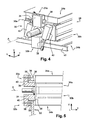
- the reversing device 28 comprises a pin 30 which is here constituted by a transverse parallelepipedal metal structure and which has a central axis A, as illustrated by FIG. figure 4 .
- the central axis A is a first axis of symmetry of the pin 30 of the reversing device 28.
- the pin 30 has a second axis B of symmetry, which is longitudinal and orthogonal to the axis A, and a third axis C of symmetry which is vertical and orthogonal to the axis A, as shown in FIG. figure 1 .
- Pin 30 illustrated at figure 4 comprises a first upper portion 30a which extends axially along the axis A and which carries the first support 24a.
- the pin 30 has a second portion 30b which extends axially and which carries the second support 24b.
- the first portion 30a includes first locking means 32a of the associated support and the second portion 30b includes second locking means 32b of the associated support, which are shown in detail in FIGS. Figures 4 and 5 .
- each support 24a, 24b comprises two locking handles 38 which are fixed at a first axial end and at a second axial end respectively of the support 24a.
- the first locking means 32a comprise two fixed jaws 34 which are fixed on a first axial end and on a second axial end of the first portion 30a of the spindle 30, respectively, symmetrically along the second axis B of symmetry.
- Each fixed jaw 34 carries a movable jaw 36 which is pivotally mounted between a rest position in which the fixed jaw 34 and the movable jaw 36 delimit between them a first housing in which the handle 38 of the associated support 24a is slidable, and a locking position in which the fixed jaw 34 and the movable jaw 36 delimit between them a second, narrower housing 40, in which the handle 38 of the associated support 24a is adapted to be mechanically locked by pinching, as illustrates it figure 5 .
- each movable jaw 36 is pivotally driven by an actuator, here a jack 42 which is shown in FIG. figure 4 and which is carried by the spindle 30, whereby the first locking means 32a are able to firmly lock the associated support 24a on the first portion 30a of the spindle 30.
- an actuator here a jack 42 which is shown in FIG. figure 4 and which is carried by the spindle 30, whereby the first locking means 32a are able to firmly lock the associated support 24a on the first portion 30a of the spindle 30.
- the second locking means 32b are identical to the first locking means 32a and are capable of fixedly locking the associated support 24b to the second portion 30b of the pin 30.
- the spindle 30 is pivotally mounted around its central axis A, in increments of half a turn, between a first position in which the first support 24a occupies its production position, the second support 24b then occupying its retracted position, and a second position in which the second support 24b occupies its production position, the first support 24a then occupying its retracted position.
- Pin 30 is here pivoted by means of an electric motor.
- each plate 22a, 22b of the floor 22 is driven from its horizontal position to its vertical safety position, illustrated in FIG. figure 3 , to prohibit access to the production station 14.
- a first barrier 60 and a second barrier are driven from a retracted position (not shown) to a safety position in which the barriers are arranged at a first axial end and at a second axial end of the production station 14 respectively.
- the production system 10 comprises a support replacement device 44, which is able to replace the support occupying a position retracted by at least a third additional support 24c of a third type of body side (not shown ).
- the support replacement device 44 comprises a pit-type magazine 46, which is arranged below the production station 14, partly below the floor 22.
- the magazine 46 comprises a support replacement zone Z which is arranged under the pin 30 so that the support 24b which occupies its retracted position is situated in this zone Z.
- the replacement device 44 comprises a carriage 48 which consists of a parallelepiped-shaped metal structure comprising in particular two longitudinal uprights 50.
- the carriage 48 has three locations 52, each of which is adapted to receive one of the supports 24a, 24b, 24c for the purpose of storing and transporting it.
- a first front location 52a is free and is arranged in the replacement zone Z of the magazine 46.
- a second intermediate location 52b carries the third support 24c.
- a third rear location 52c carries a fourth support 24d.
- the carriage 48 has a free slot and two other slots occupied by one of the four supports 24.
- the carriage 48 comprises four wheels 54 cooperating in pairs with a pair of rails (not shown) longitudinal, so that the carriage 48 is adapted to be moved longitudinally back and forth in the magazine 46.
- the carriage 48 is movably mounted in the magazine 46 between an unloading position, shown in FIG. figure 1 , in which the free location 52a of the carriage 48 is arranged in the replacement zone Z of the magazine 46, and a loading position, shown in FIG. figure 2 , in which the location 52b occupied by the third support 24c is arranged in the replacement zone Z of the magazine 46.
- the support which occupies a retracted position the support 24b at the figure 1 , is able to be unlocked from the pin 30 to occupy the free position of the carriage 38, here the location 52a, and to be carried by the carriage 48.
- one of the two other supports carried by the carriage 48 here the supports 24c, 24d, is able to be locked on the spindle 30.
- first locking means 32a and the second locking means 32b are arranged to define a longitudinal slot 56 between the axial end of the associated portion 30a, 30b and the assembly constituted by the fixed jaw 34 and the movable jaw 36 associates.
- the slot 56 is open vertically downwards when the associated portion 30a, 30b of the pin 30 carries a support 24 which occupies a retracted position, so as to allow the passage upper amounts 50 of the carriage 48 between the two slots 56 during the displacement of the carriage 48.
- the movable jaw 36 substantially drives the support 24 associated vertically upwards in order to press against the fixed jaw 40, so that the support 24 does not rest any longer. on the upper uprights 48 of the carriage 48, as illustrated by figure 5 .
- the invention also relates to a method for implementing the production system 10 previously described.
- the method comprises a plurality of successive steps including a first spindle support unloading step 30, a second support loading step selected on the spindle 30 and a third inverting step of the two supports that are carried by the spindle. 30.
- the choice of the medium to be loaded on the pin 30, said selected medium, during the second step of the method, is performed by the computerized management means which transmit a production instruction to the production system 10, the instruction determining the selected medium.
- the selected support is the third support 24c.
- the first unloading stage of support comprises a first driving phase of the carriage 48 in its unloading position in which the free location of the carriage 48, here the first front location 52a, is arranged in the replacement zone Z of the magazine 46.
- a second phase of the first stage is to unlock the support which occupies a retracted position and which is locked on the pin 30, here the support 24b, so that the support 24b is unloaded from the pin 30 and that it is carried by the carriage 30, in the first location 52a.
- the second loading step comprises a first driving phase of the carriage 48 in its loading position in which the second intermediate location 52b of the carriage 48 which carries the selected support 24c is arranged in the replacement zone Z of the magazine 46.
- a second phase of the second step is to lock on the pin 30 the support 24c selected so as to load it on the pin 30.
- the third reversal step includes a first preliminary phase which consists in driving the floor 22 from its horizontal position to its vertical safety position.
- first barrier 60 and the second barrier are driven from their retracted position to their safety position.
- a second phase of the third inversion step consists in reversing the selected support 24c which occupies a retracted position, with the support 24a occupying a production position.
- the spindle is pivoted half a turn about its axis A, as illustrated by FIG. figure 3 .
- a third phase of the third step consists in driving the floor 22 from its vertical safety position to its initial horizontal position.
- first barrier 60 and the second barrier are driven from their safety position to their retracted position.
- the new empty slot of the carriage 38 is the location 52b, which is arranged in the replacement zone Z of the magazine 46.
- the same production station is equipped with more than two production supports, thanks to which the production system 10 is able to produce as many different types of body side 12 as there are associated supports .
- the time of replacement of a support by another is limited to the time required to perform the third step of reversal, because the first loading step and the first unloading step are feasible in masked time, during the production of the cashier side.
Landscapes
- Engineering & Computer Science (AREA)
- Mechanical Engineering (AREA)
- Physics & Mathematics (AREA)
- Optics & Photonics (AREA)
- Manufacturing & Machinery (AREA)
- Chemical & Material Sciences (AREA)
- Combustion & Propulsion (AREA)
- Transportation (AREA)
- Automatic Assembly (AREA)
- Automobile Manufacture Line, Endless Track Vehicle, Trailer (AREA)
Applications Claiming Priority (2)
| Application Number | Priority Date | Filing Date | Title |
|---|---|---|---|
| FR0854443A FR2933365B1 (fr) | 2008-07-01 | 2008-07-01 | Systeme pour la production d'au moins trois types distincts d'une caisse d'un vehicule automobile et procede pour sa mise en oeuvre |
| PCT/FR2009/050895 WO2010004145A1 (fr) | 2008-07-01 | 2009-05-14 | Systeme pour la production d'au moins trois types distincts d'une caisse d'un vehicule automobile et procede pour sa mise en oeuvre |
Publications (2)
| Publication Number | Publication Date |
|---|---|
| EP2296960A1 EP2296960A1 (fr) | 2011-03-23 |
| EP2296960B1 true EP2296960B1 (fr) | 2012-01-25 |
Family
ID=40293675
Family Applications (1)
| Application Number | Title | Priority Date | Filing Date |
|---|---|---|---|
| EP09794012A Ceased EP2296960B1 (fr) | 2008-07-01 | 2009-05-14 | Systeme pour la production d'au moins trois types distincts d'une caisse d'un vehicule automobile et procede pour sa mise en oeuvre |
Country Status (9)
| Country | Link |
|---|---|
| EP (1) | EP2296960B1 (ar) |
| CN (1) | CN102083680B (ar) |
| AR (1) | AR072433A1 (ar) |
| AT (1) | ATE542629T1 (ar) |
| BR (1) | BRPI0914132A2 (ar) |
| FR (1) | FR2933365B1 (ar) |
| MA (1) | MA32423B1 (ar) |
| RU (1) | RU2489298C2 (ar) |
| WO (1) | WO2010004145A1 (ar) |
Families Citing this family (5)
| Publication number | Priority date | Publication date | Assignee | Title |
|---|---|---|---|---|
| CN102873477B (zh) * | 2012-03-13 | 2015-05-13 | 浙江金刚汽车有限公司 | 汽车生产线车型切换机构 |
| JP5926392B2 (ja) * | 2012-09-25 | 2016-05-25 | 株式会社キーレックス | 溶接装置 |
| DE202014100850U1 (de) * | 2014-02-25 | 2015-05-28 | Kuka Systems Gmbh | Wechselvorrichtung |
| US10532784B2 (en) * | 2015-06-04 | 2020-01-14 | Honda Motor Co., Ltd. | Vehicle body assembling method and vehicle body assembling apparatus |
| EP3769905B1 (de) * | 2019-07-25 | 2021-12-22 | MAGNA STEYR Fahrzeugtechnik AG & Co KG | Vorrichtung zum positionieren von kraftfahrzeugteilen und verffahren zum wahlweisen konfiguration einer solchen vorrichtung. |
Family Cites Families (5)
| Publication number | Priority date | Publication date | Assignee | Title |
|---|---|---|---|---|
| GB9109332D0 (en) * | 1991-05-01 | 1991-06-26 | Pigott Norman B | Workstation |
| DE29813669U1 (de) * | 1998-07-31 | 1999-12-23 | KUKA Schweissanlagen GmbH, 86165 Augsburg | Flexible Arbeitsstation |
| RU2221683C1 (ru) * | 2002-09-16 | 2004-01-20 | Открытое акционерное общество "ГАЗ" | Робототехнический комплекс для сварки подсборок кузова автомобиля |
| DE102005013636A1 (de) * | 2005-03-24 | 2006-10-19 | Volkswagen Ag | Bearbeitungsstation und Verfahren zur Fertigung von Karosserien |
| RU53205U1 (ru) * | 2005-12-26 | 2006-05-10 | Открытое акционерное общество "ГАЗ" (ОАО "ГАЗ") | Устройство для сборки-сварки кузова автомобиля |
-
2008
- 2008-07-01 FR FR0854443A patent/FR2933365B1/fr not_active Expired - Fee Related
-
2009
- 2009-05-14 BR BRPI0914132A patent/BRPI0914132A2/pt active Search and Examination
- 2009-05-14 WO PCT/FR2009/050895 patent/WO2010004145A1/fr not_active Ceased
- 2009-05-14 EP EP09794012A patent/EP2296960B1/fr not_active Ceased
- 2009-05-14 AT AT09794012T patent/ATE542629T1/de active
- 2009-05-14 RU RU2011103432/11A patent/RU2489298C2/ru not_active IP Right Cessation
- 2009-05-14 CN CN2009801258179A patent/CN102083680B/zh not_active Expired - Fee Related
- 2009-06-30 AR ARP090102447A patent/AR072433A1/es not_active Application Discontinuation
-
2010
- 2010-12-29 MA MA33467A patent/MA32423B1/ar unknown
Also Published As
| Publication number | Publication date |
|---|---|
| FR2933365A1 (fr) | 2010-01-08 |
| ATE542629T1 (de) | 2012-02-15 |
| FR2933365B1 (fr) | 2010-07-30 |
| RU2489298C2 (ru) | 2013-08-10 |
| AR072433A1 (es) | 2010-08-25 |
| RU2011103432A (ru) | 2012-08-10 |
| CN102083680A (zh) | 2011-06-01 |
| CN102083680B (zh) | 2013-06-12 |
| EP2296960A1 (fr) | 2011-03-23 |
| BRPI0914132A2 (pt) | 2015-10-20 |
| WO2010004145A1 (fr) | 2010-01-14 |
| MA32423B1 (ar) | 2011-06-01 |
Similar Documents
| Publication | Publication Date | Title |
|---|---|---|
| EP2296960B1 (fr) | Systeme pour la production d'au moins trois types distincts d'une caisse d'un vehicule automobile et procede pour sa mise en oeuvre | |
| EP0726860B1 (fr) | Procede et dispositif d'assemblage pour pieces de carrosserie | |
| EP0201395B2 (fr) | Dispositif d'assemblage destinés notamment aux lignes capacitaires de carrosseries | |
| EP2620392B1 (fr) | Dispositif de stockage de pièces | |
| EP0800436B1 (fr) | Atelier d'assemblage pour pieces de tolerie | |
| EP2167251B1 (fr) | Dispositif de manutention d'une charge telle qu'une bobine de tole | |
| LU87381A1 (fr) | Installation automatisee pour la pose d'une maconnerie sur une paroi | |
| FR2548636A1 (fr) | Appareil distributeur d'articles | |
| WO2014023880A1 (fr) | Procédé et installation de soudage d'éléments de carrosserie automobile avec changement rapide d'outil par rotonde élévatrice | |
| BE1001784A3 (fr) | Installation pour briqueter la paroi interieure d'une enceinte. | |
| EP0154571B1 (fr) | Machine convertible à phases séquentielles | |
| FR2709295A1 (fr) | Appareil pour le chargement de pièces comprenant une navette et une monture pivotante support de pièces entraînées en harmonie. | |
| EP2329501B1 (fr) | Ensemble de manutention pour conteneur d'assemblage de combustible nucleaire | |
| EP0864398B1 (fr) | Machine-outil pourvue d'un magasin d'outils unique à capacité de stockage élevée, et magasin d'outils destiné à équiper une machine-outil | |
| EP1150879B1 (fr) | Procede de mise en conformation geometrique pour la caisse de vehicules automobiles | |
| FR2533542A1 (fr) | Procedes et postes de preparation et de transfert d'unites de stockage, transport, et/ou manutention | |
| FR2715339A1 (fr) | Procédé et dispositif d'assemblage d'une carrosserie automobile. | |
| FR2806069A1 (fr) | Dispositif de chargement de tourets sur racks de deroulage | |
| WO2023170503A1 (fr) | Vehicule de voirie multifonctions comportant des moyens pour le changement rapide d'outils | |
| FR2615778A2 (fr) | Appareil de transport et de manutention de charges comprenant un chariot sans conducteur a fourche de levage | |
| FR2795709A1 (fr) | Module de stockage d'articles a elements de reception suspendus | |
| FR2874525A1 (fr) | Installation pour l'usinage par commande numerique de pieces | |
| FR3146449A1 (fr) | Dispositif d’aide au déplacement d’un chariot et procédé de déplacement correspondant | |
| BE1005442A3 (fr) | Procede et installation d'usinage d'elements longs, en particulier d'elements metalliques aeronautiques. | |
| CA2275948C (fr) | Installation de raboutage d'au moins deux pieces metalliques par soudage au moyen d'un faisceau a haute densite d'energie |
Legal Events
| Date | Code | Title | Description |
|---|---|---|---|
| PUAI | Public reference made under article 153(3) epc to a published international application that has entered the european phase |
Free format text: ORIGINAL CODE: 0009012 |
|
| 17P | Request for examination filed |
Effective date: 20101217 |
|
| AK | Designated contracting states |
Kind code of ref document: A1 Designated state(s): AT BE BG CH CY CZ DE DK EE ES FI FR GB GR HR HU IE IS IT LI LT LU LV MC MK MT NL NO PL PT RO SE SI SK TR |
|
| AX | Request for extension of the european patent |
Extension state: AL BA RS |
|
| REG | Reference to a national code |
Ref country code: DE Ref legal event code: R079 Ref document number: 602009004963 Country of ref document: DE Free format text: PREVIOUS MAIN CLASS: B62D0065020000 Ipc: B23K0011110000 |
|
| GRAP | Despatch of communication of intention to grant a patent |
Free format text: ORIGINAL CODE: EPIDOSNIGR1 |
|
| DAX | Request for extension of the european patent (deleted) | ||
| RIC1 | Information provided on ipc code assigned before grant |
Ipc: B23K 11/11 20060101AFI20110810BHEP Ipc: B62D 65/02 20060101ALI20110810BHEP Ipc: B23K 37/02 20060101ALI20110810BHEP |
|
| RIN1 | Information on inventor provided before grant (corrected) |
Inventor name: ROBIN, JEAN-FRANCOIS Inventor name: LEJEUNE, VINCENT |
|
| GRAS | Grant fee paid |
Free format text: ORIGINAL CODE: EPIDOSNIGR3 |
|
| GRAA | (expected) grant |
Free format text: ORIGINAL CODE: 0009210 |
|
| AK | Designated contracting states |
Kind code of ref document: B1 Designated state(s): AT BE BG CH CY CZ DE DK EE ES FI FR GB GR HR HU IE IS IT LI LT LU LV MC MK MT NL NO PL PT RO SE SI SK TR |
|
| REG | Reference to a national code |
Ref country code: GB Ref legal event code: FG4D Free format text: NOT ENGLISH |
|
| REG | Reference to a national code |
Ref country code: CH Ref legal event code: EP |
|
| REG | Reference to a national code |
Ref country code: AT Ref legal event code: REF Ref document number: 542629 Country of ref document: AT Kind code of ref document: T Effective date: 20120215 |
|
| REG | Reference to a national code |
Ref country code: IE Ref legal event code: FG4D |
|
| REG | Reference to a national code |
Ref country code: DE Ref legal event code: R096 Ref document number: 602009004963 Country of ref document: DE Effective date: 20120322 |
|
| REG | Reference to a national code |
Ref country code: NL Ref legal event code: VDEP Effective date: 20120125 |
|
| LTIE | Lt: invalidation of european patent or patent extension |
Effective date: 20120125 |
|
| PG25 | Lapsed in a contracting state [announced via postgrant information from national office to epo] |
Ref country code: NL Free format text: LAPSE BECAUSE OF FAILURE TO SUBMIT A TRANSLATION OF THE DESCRIPTION OR TO PAY THE FEE WITHIN THE PRESCRIBED TIME-LIMIT Effective date: 20120125 Ref country code: BG Free format text: LAPSE BECAUSE OF FAILURE TO SUBMIT A TRANSLATION OF THE DESCRIPTION OR TO PAY THE FEE WITHIN THE PRESCRIBED TIME-LIMIT Effective date: 20120425 Ref country code: IS Free format text: LAPSE BECAUSE OF FAILURE TO SUBMIT A TRANSLATION OF THE DESCRIPTION OR TO PAY THE FEE WITHIN THE PRESCRIBED TIME-LIMIT Effective date: 20120525 Ref country code: HR Free format text: LAPSE BECAUSE OF FAILURE TO SUBMIT A TRANSLATION OF THE DESCRIPTION OR TO PAY THE FEE WITHIN THE PRESCRIBED TIME-LIMIT Effective date: 20120125 Ref country code: NO Free format text: LAPSE BECAUSE OF FAILURE TO SUBMIT A TRANSLATION OF THE DESCRIPTION OR TO PAY THE FEE WITHIN THE PRESCRIBED TIME-LIMIT Effective date: 20120425 Ref country code: LT Free format text: LAPSE BECAUSE OF FAILURE TO SUBMIT A TRANSLATION OF THE DESCRIPTION OR TO PAY THE FEE WITHIN THE PRESCRIBED TIME-LIMIT Effective date: 20120125 |
|
| REG | Reference to a national code |
Ref country code: IE Ref legal event code: FD4D |
|
| PG25 | Lapsed in a contracting state [announced via postgrant information from national office to epo] |
Ref country code: PT Free format text: LAPSE BECAUSE OF FAILURE TO SUBMIT A TRANSLATION OF THE DESCRIPTION OR TO PAY THE FEE WITHIN THE PRESCRIBED TIME-LIMIT Effective date: 20120525 Ref country code: LV Free format text: LAPSE BECAUSE OF FAILURE TO SUBMIT A TRANSLATION OF THE DESCRIPTION OR TO PAY THE FEE WITHIN THE PRESCRIBED TIME-LIMIT Effective date: 20120125 Ref country code: GR Free format text: LAPSE BECAUSE OF FAILURE TO SUBMIT A TRANSLATION OF THE DESCRIPTION OR TO PAY THE FEE WITHIN THE PRESCRIBED TIME-LIMIT Effective date: 20120426 Ref country code: FI Free format text: LAPSE BECAUSE OF FAILURE TO SUBMIT A TRANSLATION OF THE DESCRIPTION OR TO PAY THE FEE WITHIN THE PRESCRIBED TIME-LIMIT Effective date: 20120125 Ref country code: PL Free format text: LAPSE BECAUSE OF FAILURE TO SUBMIT A TRANSLATION OF THE DESCRIPTION OR TO PAY THE FEE WITHIN THE PRESCRIBED TIME-LIMIT Effective date: 20120125 |
|
| REG | Reference to a national code |
Ref country code: AT Ref legal event code: MK05 Ref document number: 542629 Country of ref document: AT Kind code of ref document: T Effective date: 20120125 |
|
| PG25 | Lapsed in a contracting state [announced via postgrant information from national office to epo] |
Ref country code: CY Free format text: LAPSE BECAUSE OF FAILURE TO SUBMIT A TRANSLATION OF THE DESCRIPTION OR TO PAY THE FEE WITHIN THE PRESCRIBED TIME-LIMIT Effective date: 20120125 |
|
| PG25 | Lapsed in a contracting state [announced via postgrant information from national office to epo] |
Ref country code: RO Free format text: LAPSE BECAUSE OF FAILURE TO SUBMIT A TRANSLATION OF THE DESCRIPTION OR TO PAY THE FEE WITHIN THE PRESCRIBED TIME-LIMIT Effective date: 20120125 Ref country code: DK Free format text: LAPSE BECAUSE OF FAILURE TO SUBMIT A TRANSLATION OF THE DESCRIPTION OR TO PAY THE FEE WITHIN THE PRESCRIBED TIME-LIMIT Effective date: 20120125 Ref country code: IE Free format text: LAPSE BECAUSE OF FAILURE TO SUBMIT A TRANSLATION OF THE DESCRIPTION OR TO PAY THE FEE WITHIN THE PRESCRIBED TIME-LIMIT Effective date: 20120125 Ref country code: EE Free format text: LAPSE BECAUSE OF FAILURE TO SUBMIT A TRANSLATION OF THE DESCRIPTION OR TO PAY THE FEE WITHIN THE PRESCRIBED TIME-LIMIT Effective date: 20120125 Ref country code: CZ Free format text: LAPSE BECAUSE OF FAILURE TO SUBMIT A TRANSLATION OF THE DESCRIPTION OR TO PAY THE FEE WITHIN THE PRESCRIBED TIME-LIMIT Effective date: 20120125 Ref country code: SI Free format text: LAPSE BECAUSE OF FAILURE TO SUBMIT A TRANSLATION OF THE DESCRIPTION OR TO PAY THE FEE WITHIN THE PRESCRIBED TIME-LIMIT Effective date: 20120125 Ref country code: SE Free format text: LAPSE BECAUSE OF FAILURE TO SUBMIT A TRANSLATION OF THE DESCRIPTION OR TO PAY THE FEE WITHIN THE PRESCRIBED TIME-LIMIT Effective date: 20120125 |
|
| BERE | Be: lapsed |
Owner name: RENAULT S.A.S. Effective date: 20120531 |
|
| PG25 | Lapsed in a contracting state [announced via postgrant information from national office to epo] |
Ref country code: IT Free format text: LAPSE BECAUSE OF FAILURE TO SUBMIT A TRANSLATION OF THE DESCRIPTION OR TO PAY THE FEE WITHIN THE PRESCRIBED TIME-LIMIT Effective date: 20120125 Ref country code: SK Free format text: LAPSE BECAUSE OF FAILURE TO SUBMIT A TRANSLATION OF THE DESCRIPTION OR TO PAY THE FEE WITHIN THE PRESCRIBED TIME-LIMIT Effective date: 20120125 |
|
| PLBE | No opposition filed within time limit |
Free format text: ORIGINAL CODE: 0009261 |
|
| STAA | Information on the status of an ep patent application or granted ep patent |
Free format text: STATUS: NO OPPOSITION FILED WITHIN TIME LIMIT |
|
| PG25 | Lapsed in a contracting state [announced via postgrant information from national office to epo] |
Ref country code: MC Free format text: LAPSE BECAUSE OF NON-PAYMENT OF DUE FEES Effective date: 20120531 |
|
| 26N | No opposition filed |
Effective date: 20121026 |
|
| PG25 | Lapsed in a contracting state [announced via postgrant information from national office to epo] |
Ref country code: AT Free format text: LAPSE BECAUSE OF FAILURE TO SUBMIT A TRANSLATION OF THE DESCRIPTION OR TO PAY THE FEE WITHIN THE PRESCRIBED TIME-LIMIT Effective date: 20120125 |
|
| REG | Reference to a national code |
Ref country code: DE Ref legal event code: R097 Ref document number: 602009004963 Country of ref document: DE Effective date: 20121026 |
|
| PG25 | Lapsed in a contracting state [announced via postgrant information from national office to epo] |
Ref country code: MK Free format text: LAPSE BECAUSE OF FAILURE TO SUBMIT A TRANSLATION OF THE DESCRIPTION OR TO PAY THE FEE WITHIN THE PRESCRIBED TIME-LIMIT Effective date: 20120125 Ref country code: BE Free format text: LAPSE BECAUSE OF NON-PAYMENT OF DUE FEES Effective date: 20120531 |
|
| PG25 | Lapsed in a contracting state [announced via postgrant information from national office to epo] |
Ref country code: ES Free format text: LAPSE BECAUSE OF FAILURE TO SUBMIT A TRANSLATION OF THE DESCRIPTION OR TO PAY THE FEE WITHIN THE PRESCRIBED TIME-LIMIT Effective date: 20120506 |
|
| PG25 | Lapsed in a contracting state [announced via postgrant information from national office to epo] |
Ref country code: MT Free format text: LAPSE BECAUSE OF FAILURE TO SUBMIT A TRANSLATION OF THE DESCRIPTION OR TO PAY THE FEE WITHIN THE PRESCRIBED TIME-LIMIT Effective date: 20120125 |
|
| REG | Reference to a national code |
Ref country code: CH Ref legal event code: PL |
|
| PG25 | Lapsed in a contracting state [announced via postgrant information from national office to epo] |
Ref country code: LI Free format text: LAPSE BECAUSE OF NON-PAYMENT OF DUE FEES Effective date: 20130531 Ref country code: CH Free format text: LAPSE BECAUSE OF NON-PAYMENT OF DUE FEES Effective date: 20130531 |
|
| PG25 | Lapsed in a contracting state [announced via postgrant information from national office to epo] |
Ref country code: LU Free format text: LAPSE BECAUSE OF NON-PAYMENT OF DUE FEES Effective date: 20120514 |
|
| PG25 | Lapsed in a contracting state [announced via postgrant information from national office to epo] |
Ref country code: HU Free format text: LAPSE BECAUSE OF FAILURE TO SUBMIT A TRANSLATION OF THE DESCRIPTION OR TO PAY THE FEE WITHIN THE PRESCRIBED TIME-LIMIT Effective date: 20090514 |
|
| REG | Reference to a national code |
Ref country code: FR Ref legal event code: PLFP Year of fee payment: 7 |
|
| REG | Reference to a national code |
Ref country code: FR Ref legal event code: PLFP Year of fee payment: 8 |
|
| REG | Reference to a national code |
Ref country code: FR Ref legal event code: PLFP Year of fee payment: 9 |
|
| REG | Reference to a national code |
Ref country code: FR Ref legal event code: PLFP Year of fee payment: 10 |
|
| PGFP | Annual fee paid to national office [announced via postgrant information from national office to epo] |
Ref country code: DE Payment date: 20180522 Year of fee payment: 10 |
|
| PGFP | Annual fee paid to national office [announced via postgrant information from national office to epo] |
Ref country code: TR Payment date: 20180511 Year of fee payment: 10 Ref country code: FR Payment date: 20180522 Year of fee payment: 10 |
|
| PGFP | Annual fee paid to national office [announced via postgrant information from national office to epo] |
Ref country code: GB Payment date: 20180518 Year of fee payment: 10 |
|
| REG | Reference to a national code |
Ref country code: DE Ref legal event code: R119 Ref document number: 602009004963 Country of ref document: DE |
|
| GBPC | Gb: european patent ceased through non-payment of renewal fee |
Effective date: 20190514 |
|
| PG25 | Lapsed in a contracting state [announced via postgrant information from national office to epo] |
Ref country code: GB Free format text: LAPSE BECAUSE OF NON-PAYMENT OF DUE FEES Effective date: 20190514 Ref country code: DE Free format text: LAPSE BECAUSE OF NON-PAYMENT OF DUE FEES Effective date: 20191203 |
|
| PG25 | Lapsed in a contracting state [announced via postgrant information from national office to epo] |
Ref country code: FR Free format text: LAPSE BECAUSE OF NON-PAYMENT OF DUE FEES Effective date: 20190531 |
|
| PG25 | Lapsed in a contracting state [announced via postgrant information from national office to epo] |
Ref country code: TR Free format text: LAPSE BECAUSE OF NON-PAYMENT OF DUE FEES Effective date: 20190514 |